NikolaTesla FIT XL PRF0186750 - Cooker ELICA - Free user manual and instructions
Find the device manual for free NikolaTesla FIT XL PRF0186750 ELICA in PDF.
| Product type | Induction cooktop with integrated hood |
| Brand | Elica |
| Model | NikolaTesla FIT XL PRF0186750 |
| Power supply | 220-240 V / 50-60 Hz, max power 7.2 kW |
| Number of cooking zones | 4 induction zones |
| Power levels | 9 levels + 2 boosters (5 min and 15 min) |
| Main functions | Booster, Bridge, Automatic Heat Up, Temperature Manager, Timer, Pause, Key Lock |
| Pan detection | Yes, automatic stop without cookware |
| Display | Touch screen with cooking zones, timer and residual heat indicator |
| Suction power | 3 speeds + 2 boosters, automatic suction |
| Suction type | Extraction version or recirculation version |
| Filters | Washable metal grease filter (dishwasher safe); regenerable activated carbon/ceramic filter (45 min at 200°C) |
| Saturation indicator | Yes, resettable |
| Maintenance | Clean the glass with a soft cloth and neutral detergent; no steam or abrasives |
| Safety | Automatic shut-off, key lock, pan detection, adjustable power limit |
| Maximum power per zone | Up to 3.5 kW (estimate) |
| Dimensions (W x D) | Approximately 90 x 50 cm (estimate for FIT XL) |
| Cutout | Cutout according to worktop, thickness 2-6 cm |
| Weight | Approximately 25 kg (estimate) |
| Spare parts | Filters, power cable, accessory kit (optional) |
| General information | For domestic use only, comply with local installation standards |
Frequently Asked Questions - NikolaTesla FIT XL PRF0186750 ELICA
User questions about NikolaTesla FIT XL PRF0186750 ELICA
0 question about this device. Answer the ones you know or ask your own.
Ask a new question about this device
Download the instructions for your Cooker in PDF format for free! Find your manual NikolaTesla FIT XL PRF0186750 - ELICA and take your electronic device back in hand. On this page are published all the documents necessary for the use of your device. NikolaTesla FIT XL PRF0186750 by ELICA.
USER MANUAL NikolaTesla FIT XL PRF0186750 ELICA
EN Instruction on mounting and use
natural_image
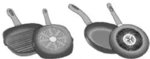
Illustration of kitchenware including a plate with a cross symbol, a pot with a lid, and a pan (no text or symbols)natural_image
Two cooking panes with handles, one open showing a circular pattern and the other closed, both with a 'NO!' text label (no other text or symbols)natural_image
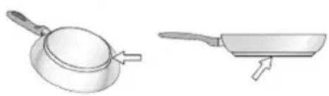
Illustration of a frying pan and its side view with a label 'SI!' (no text or symbols on the objects themselves)text_image
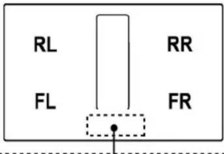
RL FL RR FR
text_image
10 9 8 7 5 + + + 8 8 8 - - 6 2 RL HOOD 11 12 6 2 RR 8 8 8 ① (A) 5 1 14 4 FL 2 6 13 FILTER 8 FR 2 6Tasti a sfioramento (TOUCH) / Display
● Residual Heat Indicator
● Temperature Manager (Warming Function)
chemical
Chemical reaction diagram showing transformation of compounds III° and IV° into II° and I° with labeled positions and directional arrowsStrictly observe the instructions in this manual. All liability is declined for any problems, damage or fires caused by failure to comply with the instructions in this manual. The device is intended for domestic use only, to cook food and extract the fumes generated by cooking. No other use is allowed (e.g. heating rooms). The manufacturer declines any liability for inappropriate use or incorrect control settings. The device may have different aesthetic features with respect to the illustrations in this handbook, however the operating, maintenance and installation instructions remain the same.
Read the instructions carefully: they include important information about installation, use and safety.
Do not make electrical changes to the device.
Before installing the device, make sure that none of the components are damaged. Otherwise, contact the dealer and do not continue with the installation.
Check that the device is intact before continuing with installation. Otherwise, contact the dealer and do not continue with the installation.
Note: the parts marked with the symbol "(*)" are optional accessories supplied only with some models or otherwise not supplied, but available for purchase.
1. Warnings
Please note! Pay strict attention to the following instructions: ● The device must be disconnected from the electric power supply before carrying out any installation work. ● Installation or maintenance must be performed by a qualified technician, in compliance with the manufacturer's instructions and local safety regulations. Do not repair or replace any part of the device unless specifically stated in the operating manual. ● By law, the appliance must be earthed. ● The power cable must be long enough to allow the device built into the unit to be connected to the power supply. ● In order for the installation to comply with current safety regulations, an approved omnipolar circuit breaker is required that guarantees complete disconnection of the mains in overvoltage category III, in accordance with the installation rules. ● Do not use power strips or extension cords. ● Once installation is complete, the electrical components must no longer be accessible by the user. ● The device and its accessible parts get hot during use. Be careful not to touch the heating elements. ● Ensure that children do not play with the device; keep children away and supervise them because the accessible parts may become very hot during use. ● For people with pacemakers and active implants, it is important to check, prior to using the induction hob, that their pacemaker is compatible with the device. ● Do not touch the heating elements of the device during and after use. ● Avoid contact with cloths or any other flammable material until all the hob components have cooled down sufficiently, risk of fire ● Do not place flammable material on or near the device. ● Overheated fats and oils easily catch fire. Supervise the cooking of fatty or oily food. ● If the surface is cracked, switch the device off immediately to prevent the risk of an electric shock. ● The device is not intended to be operated with an external timer or a separate remote control system. ● Unattended cooking on a device with oil or fat can be dangerous and may cause a fire. ● The cooking process must be supervised. A short cooking process must be constantly monitored. ● NEVER attempt to put fires out using water. Instead, turn off the device and smother the flames, for example with a lid or a fire blanket. Fire hazard: do not place objects on the cooking surfaces. ● Do not use steam cleaners, risk of electric shock. ● Do not place metal objects, such as knives, forks, spoons or lids on the device because they could become hot. ● Before connecting the device to the electrical network: check the data plate (on the bottom of the device) to ensure that the voltage and power correspond to the mains supply and that the power socket is suitable. If in doubt, consult a qualified electrician.
Important: ● After use, turn off the hob at the switch and do not rely on the pan detector. ● Prevent liquids from boiling over, so turn the heat down when boiling or heating liquids. ● Do not leave the heating elements turned on with empty pots and pans or with no pans. ● Switch off the relevant hot plate when you have finished cooking. ● Never use aluminium foil for cooking and never place products packaged in aluminium on the hob. The aluminium would melt and irreparably damage your device. ● Never heat a tin or can containing foods without opening it first: it might explode! ● This warning also applies to all other types of hobs. ● High power levels such as the Booster function should not be used to heat certain liquids, such as oil for frying. Excessive heat may be dangerous. In these cases, we recommend the use of a lower power level. ● Containers must be placed directly on the hob and in the centre. Under no circumstances may any other objects be placed between the pan and the hob. ● If the temperature becomes high, the device automatically decreases the power level of the cooking zones. ● Before doing any cleaning or maintenance work, disconnect the device from the mains power supply by removing the plug or turning off the mains switch. Wear protective gloves for all installation and maintenance operations. The device can be used by children over the age of eight and by people with impaired physical, sensory or mental abilities or lacking in experience or the necessary knowledge provided that they are supervised or after they have received instruction about how to safely use the device and understand the inherent dangers. Children must be supervised to ensure they do not play with the device. Cleaning and maintenance must never be performed by children unless they are properly supervised. The room must be properly ventilated when the device is used at the same time as other gas-powered devices, or powered by other fuel. The device must be regularly cleaned both internally and externally (AT LEAST ONCE A MONTH), in strict accordance with the maintenance instructions. Failure to follow the rules for device cleaning and filter replacement and cleaning may result in a fire hazard. Food must never be
cooked flambè. Using a naked flame may damage the filters and cause a fire hazard; it must, therefore, be avoided under all circumstances. Extra care must be taken when frying to prevent the oil from overheating and catching fire. • Please note! The accessible parts of the device may become hot when the hob is switched on. • Please note! Do not connect the device to the electric power supply until installation has been fully completed. The regulations laid down by local authorities must be strictly followed with regard to the technical and safety measures to adopt for fume extraction. • The extracted air must not be conveyed through the same ducts used to extract the fumes generated by gas combustion or other types of combustion devices. Never use the device without the grille properly installed! Only use the fastening screws supplied with the device for installation, or if not supplied, purchase the correct type of screws. Use screws of the right length, as indicated in the installation guide. • When the device is used together with other devices powered with non-electrical energy, the negative pressure of the room must not exceed 4 Pa (4 x 10•5 bar). This manual must be stored for future consultation at any time. If sold, transferred or moved, it must remain with the device.• Range hoods and other cooking fume extractors may adversely affect the safe operation of appliances burning gas or other fuels (including those in other rooms) due to back flow of combustion gases. These gases can potentially result in carbon monoxide poisoning. After installation of a range hood or other cooking fume extractor, the operation of flued gas appliances should be tested by a competent person to ensure that back flow of combustion gases does not occur. • Range hoods and other cooking fume extractors may adversely affect the safe operation of appliances burning gas or other fuels (including those in other rooms) due to back flow of combustion gases. These gases can potentially result in carbon monoxide poisoning. After installation of a range hood or other cooking fume extractor, the operation of flued gas appliances should be tested by a competent person to ensure that back flow of combustion gases does not occur.

Electrical connection
Fig. 7 - 7.1 - 7.2 - 7.3
- Disconnect the device from the electric power supply. • Installation must be carried out by professionally qualified personnel with knowledge of the regulations in force for installation and safety. • The manufacturer denies all liability to persons, animals or property if the guidelines provided in this chapter are not followed. • The power cable must be long enough to allow the hob to be removed from the worktop. • Make sure that the voltage on the serial number data plate on the bottom of the device corresponds to that of the domestic environment where it will be installed. • Do not use extension leads. • The earth power cable must be 2cm longer than the other cables. • If the electrical appliance is not supplied with a power cable, use one with a minimum conductor diameter of 2.5 mm2 for power up to 7200 Watt; for higher power levels, the diameter must be 4 mm2. • The temperature must not reach 50°C above room temperature anywhere along the cable. ● The appliance is intended for permanent connection to the power supply.
- Please note! Before reconnecting the circuit to the mains power supply, make sure that it is working correctly, always check that the power cable is correctly installed. - Please note! The interconnection cable must be replaced by the authorised technical support service or by a person with similar qualifications.
Note : the product is equipped with a Power Limitator function, which allows a maximum power limit to be set The limit must be set at the time of the product's connection to the electrical network or when the electrical network itself is reconnected (within the following 2 minutes). Size the electrical system protection according to the selected Power Limitation level. For the Power Limitation setting sequence, see the Operation section of this manual.
Installation
- Both electric and mechanical installation must be carried out by specialised personnel.
The electrical appliance is designed to be built into a work top with a thickness of 2-6 cm in the case of TOP installation; 2.5-6 cm in the case of FLUSH installation.
The minimum distance between the hob and the wall must be at least 5 cm in front, at least 4 cm on the sides and at least 50 cm from overhead wall units.
NB = The recommended distances are given as examples: when planning the spaces, the indications of the kitchen manufacturer must be observed.
Mounting
Before starting the installation:
• After unpacking the product, check that it has not been damaged during transport and in the event of problem, please contact the reseller or the Customer support service before installing it.
- Check that the product is the right size for the installation area.
- Check for accessories (e.g. bags containing screws, warranty certificates, etc.) inside the packaging (placed there for transport reasons). Remove and keep them safe, if present.
- Also check that there is a power socket near the installation area.
Preparing the cabinet for installation:
- The product cannot be installed above cooling appliances, dishwashers, heaters, ovens, washing machines and dryers.
- Create the cut-outs in the cabinet before inserting the hob and carefully remove any shavings or sawdust.
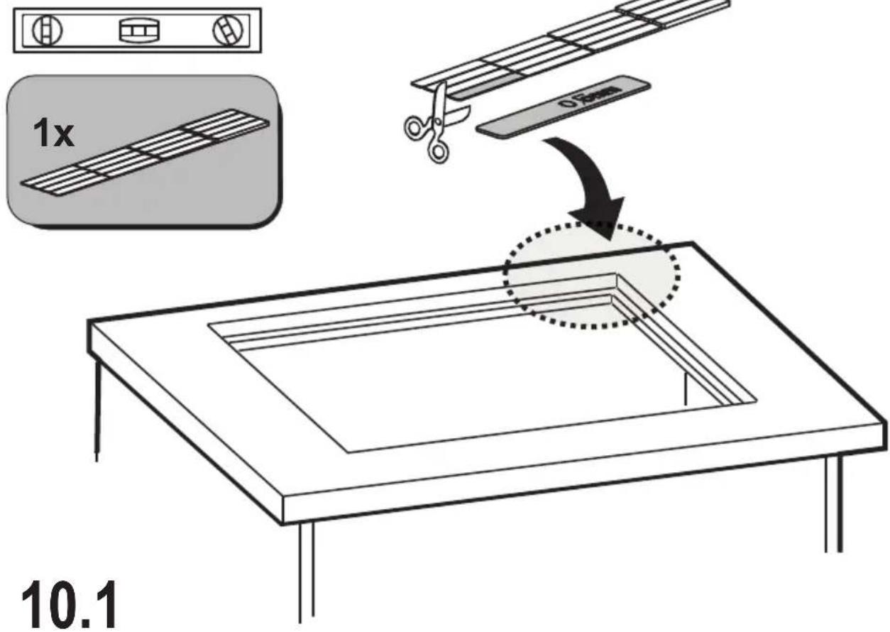
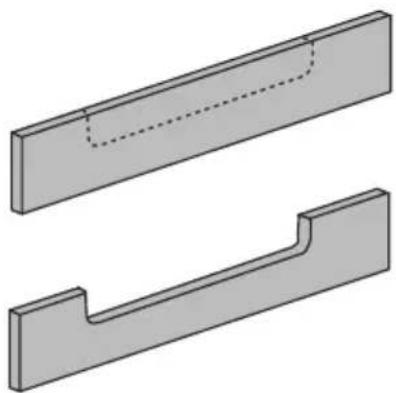
- to optimise the filter installation, it is advisable to cut a slot in the plinth to insert a grille (available on the market)
IMPORTANT: use a single-component adhesive sealant (S), which withstands temperatures up to 250°; before installation, thoroughly clean the surfaces to stick and eliminate any substance that may compromise adhesion, (e.g. release agents, preservatives, fats, oil, dust, traces
of old adhesives, etc.); the adhesive should be uniformly spread all around the outside of the frame; after sticking, leave the adhesive to dry for about 24 hours.
Caution! Failure to install screws and fasteners in accordance with these instructions may result in electrical hazards.
Note: to ensure the correct installation of the product, it is recommended to tape the pipes using an adhesive with the following characteristics:
- soft elastic PVC film, with an acrylic-based adhesive
- compliant with DIN EN 60454 regulations
- flame retardant
- excellent resistance to wear
- resistant to temperature fluctuations
- can be used at low temperatures
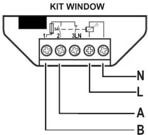
The device can also be used in combination with a Window sensor KIT (not supplied by the manufacturer).
If the Window sensor KIT is installed (only in the case of use in EXTRACTOR mode), air extraction will halt every time the window in the room, on which the KIT is applied, is closed.
- The KIT must be electrically connected to the device by qualified and specialised technical personnel.
- The KIT must be certified separately in accordance with the safety standards for the component and its use with the device. Installation must be carried out in accordance with current regulations for domestic systems.
PLEASE NOTE:
- the wiring of the KIT to be connected to the device must be part of a certified safety extra-low voltage (SELV) circuit.
- the manufacturer of this device declines all liability for any inconvenience, damage or fires caused by defects and/or problems associated with the malfunction and/or incorrect installation of the KIT.
This device is marked in compliance with the European Directive 2012/19/EC - UK SI 2013 No3113, Waste Electrical and Electronic Equipment (WEEE). By ensuring that this device is disposed of correctly, the user will help prevent potential negative impacts on the environment and human health.
The symbol on the device or documentation provided indicates that this device must not be treated as domestic waste, but must be taken to a suitable waste collection site for the recycling of electrical and electronic appliances. Dispose of it in accordance with local regulations for waste disposal. For further information about the treatment, recovery and recycling of this device, please contact your local authority, the collection service for household waste or the shop from where the device was purchased.
Device designed, tested and developed in compliance with regulations on:
- Safety: EN/IEC 60335-1; EN/IEC 60335-2-6, EN/IEC 60335-2-31, EN/IEC 62233.
• Performance: EN/IEC 61591; ISO 5167-1; ISO 5167-3; ISO 5168; EN/IEC 60704-1; EN/IEC 60704-2-13; EN/IEC 60704-3;
ISO 3741; EN 50564; IEC 62301. EN 60350-2;
- EMC: EN 55014-1; CISPR 14-1; EN 55014-2; CISPR 14-2; EN/IEC 61000-3-3; EN/IEC 61000-3-12.
Recommendations for correct use in order to reduce the impact on the environment: When you start cooking, turn the device on at minimum speed, leaving it on for a few minutes when you have finished cooking. Increase the speed only if there is a large quantity of fumes and steam, using the Booster function only in extreme cases. To keep the odour reduction system running efficiently, replace the carbon filter/s when necessary. To ensure the high performance of the grease filter, clean it when necessary. To improve efficiency and minimise noise, use the maximum duct diameter indicated in this manual.
2. Use
Cooking containers
Only use pans that carry the

symbol.
Important:
to avoid permanent damage to the hob surface, do not use:
- containers with a base that is not perfectly flat;
• metal containers with an enamelled base; - containers with a rough base, to avoid scratching the hob surface;
- never place hot pots and pans on the surface of the hob's control panel.
Not all pans suitable for induction work in an efficient manner due to the base only partially consisting of ferromagnetic material! When purchasing pots or pans ensure that:
- that the base is made entirely from ferromagnetic material. If this is not the case, the efficacy of the transmission of heat is lessened and the uniformity of heat and the temperature of the pot/pan may not be suitable for cooking.
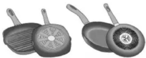
natural_image
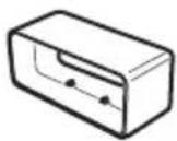
Illustration of kitchenware including a plate with a lid and a pan with a lid (no text or symbols)NO!
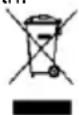
- The base does not contain aluminium: the crockery does not heat and may not be recognised by the inductors.
natural_image
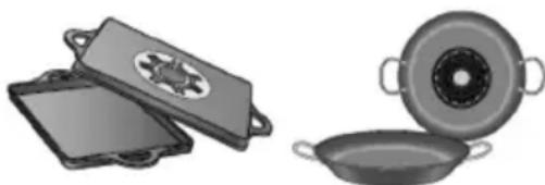
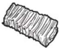
Two grayscale illustrations of frying panes with handles and a circular lid, shown from different angles (no text or symbols)NO!
- Bases that are not flat or that have rough surfaces.
These lower the contact surface area between the inductor and the pan, lowering efficiency and harming the cooking experience.
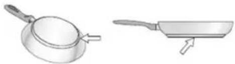
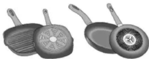
natural_image
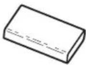
Illustration of a frying pan and its side view showing the exterior (no text or symbols)YES!
Important: never put hot pots or pans on the hob control panel surface.
Pre-existing containers
You can check if the pot material is magnetic simply by using a magnet. Pots are not suitable if they are not magnetically detectable. The indications from the previous paragraph also apply here.
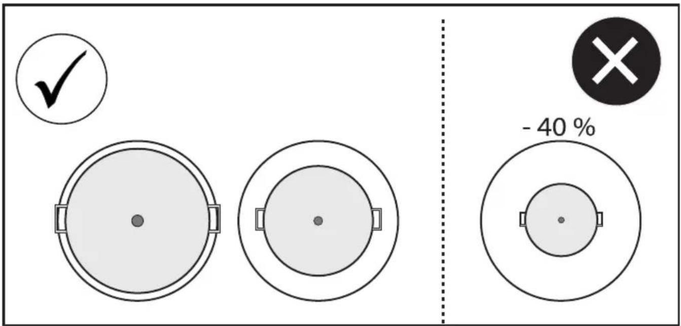
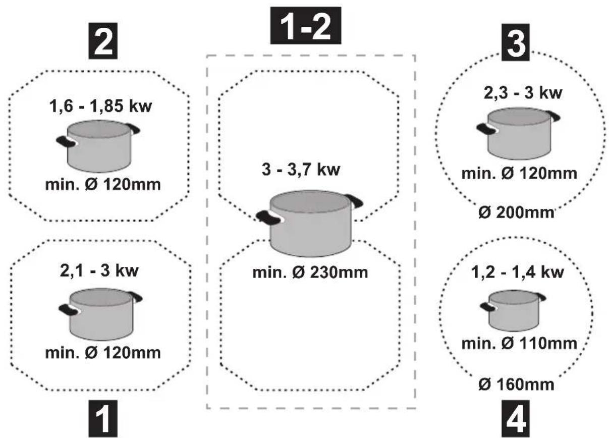
Recommended pan bottom diameters
IMPORTANT: if the pots are not of the correct size, the cooking zones will not switch on.
To see the minimum pot diameters for each individual zone, consult the illustrated section of this manual.
Energy saving
Recommendations for best results:
- Use pots and pans with a bottom diameter equal to that of the cooking zone.
- Use only pots and pans with flat bottoms.
- Where possible, keep the lid on pots during cooking
- Cook vegetables, potatoes, etc. with a minimal amount of water to reduce cooking time.
- Use a pressure cooker, as it further reduces the energy consumption and cooking time
- Place the pot in the centre of the cooking zone outlined on the hob.
Using the hob
The induction cooking system is based on the physical phenomenon of magnetic induction. The main characteristic of this system is the direct transfer of energy from the generator to the pot.
Advantages:
When compared to electric hobs, your induction hob is:
- Safer: lower temperature on the glass surface.
- Faster: shorter food heating times.
- More accurate: the hob immediately reacts to your commands
- More efficient: 90% of the absorbed energy is transformed into heat. Moreover, once the pot is removed from the hob, heat transmission is immediately interrupted, avoiding unnecessary heat losses.
Using the extractor fan
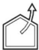
The extraction system can be used in two versions: external extraction and evacuation or as a filter with internal recirculation.
Consult the website www.elica.com and www.shop.elica.com to view the full range of available kits for carrying out the various installations in filter and suction versions.

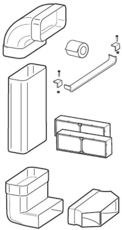
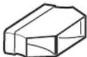
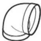
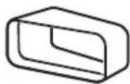
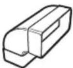
Extraction version
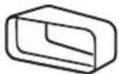
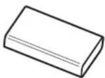
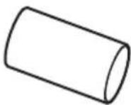
The fumes are evacuated towards the outside through a series of pipes (bought separately) fastened to the supplied connecting flange.
The diameter of the exhaust pipe must be equivalent to the diameter of the connecting ring:
- for rectangular outlets 222 x 89 mm
- for circular outlets ∅ 150 mm (*)
For more information, see the page relative to the extraction version in the illustrated part of this manual. Connect the product to wall-mounted exhaust pipes and holes with a diameter equivalent to the air outlet (connecting flange).
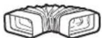
Using wall-mounted exhaust pipes and holes with a smaller diameter may reduce the efficiency of extraction and drastically increase noise levels.
All responsibility in this regard is therefore denied.
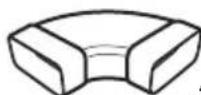
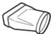
! Keep duct as short as possible.
Use ducting with the least possible number of curves (maximum angle: 90°).
① Avoid drastic changes in the ducting diameter.

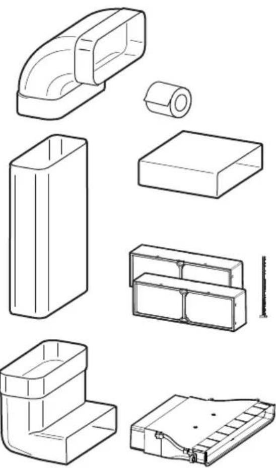
Filtration version
The extracted air will be filtered in special grease filters and odour filters before being sent back into the room. For more information, see the page relating to accessories in the installation manual - Filter version.
Warning: If the outlet is inside the cabinet, create an air vent through the plinth panel measuring at least 120cm ^4 .
3. Operation
Control panel
text_image
RL FL RR FR
text_image
10 9 8 7 5 + + + 8 8 8 - - 6 2 RL HOOD 11 12 6 2 RR 8 8 8 ① (A) 5 1 14 4 FL 2 6 13 FILTER 8 FR 2 6Touch buttons (TOUCH) / Display
- ON/OFF hob/extractor system
- Selection of the cooking zones / Cooking zone display
- Increase/decrease cooking power level and extraction speed (power) Display the cooking power level and extraction speed (power)
- Activate "STAND ALONE" timer Display : "STAND ALONE" timer / Cooking Zones Timer.
- Increase/Decrease "STAND ALONE" Timer time / Cooking Zones timer
- Activation of Cooking Zones Timer Indicator of Cooking Zones Timer active
-
Automatic Heat Up Activation.
-
Temperature Function Manager activation (Warming
-
Pause
-
Key Lock
-
Indicator Extractor active Activate Filter Saturation Indicator
-
Extractor Selection/Activation Extractor Display Display saturation carbon/ceramic Filter - Grease filter
-
Reset Filter Saturation
-
Activation of extractor automatic function
USING THE HOB
Before you begin, it is important to know:
All functions of this cooktop are designed to comply with the most stringent safety regulations.
For this reason:
- Some functions will not be activated, or will be automatically deactivated, in the absence of pots on the burners or when they are poorly positioned.
- In other cases the activated functions will be automatically deactivated after a few seconds, if the specific function requires a further setting that has not been selected (e.g.: "Turn the cooktop on" without "Selecting the cooking zone" and the "Operating temperature", or the "Lock Function" or the "Timer" function).
Caution! In the case (for example) of prolonged use, the cooking zone may not immediately shut down because it is in the cooling phase; the “H” symbol will appear on the cooking zone display, to indicate the execution of this phase. Wait for the display to turn off before approaching the cooking zone.
Cooking zone display
The following is shown on the cooking zone displays:
| Cooking zone on | 0 |
| Power level | 1...9 P |
| Residual Heat Indicator | H |
| Pot Detector | y |
| Bridge Function active | n |
| Temperature ManagerFunction active | o |
| Pause function | 11 |
| Automatic Heat UP function | A |
Hob characteristics
● Safe Activation
The product is activated only in the presence of pots on the cooking zone: the heating process does not start or is interrupted if there are no pots, or if these are removed.
- Pot Detector
The product automatically detects the presence of pots on the cooking zones.
● Safety Shut Down
For safety reasons, each cooking zone has a maximum operating time, which depends on the maximum power level set.
● Residual Heat Indicator
When one or more cooking zones shut down, the presence of residual heat is indicated by a visual signal on the corresponding zone display, by way of the “H” symbol.
Operation
Note: Before activating any functions, the desired zone must be activated
- Switch-on
Press (touch) briefly ON/OFF (1) hob/extractor: the symbol lights up; continuing to press, all the available functions will become visible for a few moments, e, after which only the main ones will remain active; the others can be used, and will be activated, subsequently, during use of the device.
IMPORTANT:
all the available functions will be illuminated with light intensity, which will become more intense only when they are activated.
Press again to turn off
Note: This function has priority over the others.
- Selecting the cooking zones
Press (touch) briefly the Selection/Display (2) area corresponding to the desired cooking area.
Power Level
The hob features 9 power levels Touch and slide your fingers along the Selection bar (3): to the right to increase the level of power; to the left to decrease the level of power. The power level set will be displayed in the Selection/Display area (2)
● Power Booster
The product features a supplementary power level (after level 5), which remains active for 5 minutes, after which the temperature returns to the previously set value.
Touch and slide with your fingers along the Selection bar (3) (above the level 9) and activate the Power Booster
The Power Booster level is indicated in the Selection / Display area (2) with the symbol" P"
● Key Lock
The Key Lock allows cooktop settings to be blocked, thus preventing accidental tampering, leaving set functions active.
Activation:

Repeat the operation to deactivate.
Note: if any other function is pressed during the active Key

Lock, the symbol 🔍, will flash to indicate that the function is in use and must be deactivated if necessary in order to use the hob.
● Automatic Heat UP
The Automatic Heat UP function allows the set power to be reached more quickly; with this function it is possible to cook food faster without the risk of burning it, insofar as the temperature does not exceed the set level.
This function is available for power levels 1-8.
Activation:
• from the cooking zone on press
- a flashing "R" is shown in the Display (2) which alternates with the power set in the cooking zone

Increasing the power level of the cooking zone: the Automatic Heat Up function remains active, with the new temperature setting;
Decreasing the power level of the cooking zone: the Automatic Heat function is deactivated.
Note: by selecting another cooking zone at the same time, the
symbol (7) will return to being illuminated with a slight intensity light, and it will be possible to proceed, also for this area, to activation of the function; the function remains active in the area where it has already been set, as indicated in the Display (2)
● Temperature Manager (Warming Function)
Temperature Manager is a control function that allows the maintaining of heat at a constant temperature, at an optimised power level; ideal to keep ready-cooked foods warm. The Temperature Manager function is activated the first time the
key is pressed
The symbol appears in the display (2) of the zone that is working in the Temperature Manager
Note: by selecting another cooking zone at the same time, the
symbol (8) will return to being illuminated with a slight intensity light, and it will be possible to proceed, also for this area, to activation of the function; the function remains active in the area where it has already been set, as indicated in the Display (2)
- Press (8) again to deactivate and switch off, until bringing of the level shown in the Display (2) to "☐".
Note: if there are several zones working in the Temperature Manager (Warming Function), first select the desired zone using the Selection zone (2); the function can also be deactivated via the Selection Bar (3), bringing the Power Level to "☐".
Pause
The Pause function allows active functions on the cooktop to be suspended, bringing the cooking power to zero.
Activation:
- press “| |” (9)
- a flashing “| |” is shown in the displays (2)
To deactivate the function:
- press ||(9) the Selection Bar (3) lights up
- press/slide on the Selection Bar (3) to deactivate the function
Note: deactivation restores the conditions of the hob before the pause; the hob continues to work with the same settings previously set.
Note: if after 10 minutes the Pause Function is not deactivated, the hob switches off automatically.
Note: the Pause Function does not affect the extraction.
● "STAND ALONE" Timer
The Timer function is a countdown independent of the cooking zones (and the extraction zone).
The timer is activated by pressing the Zone/Display (4)
Use the symbols - + (5) to set the duration of the Timer, which is displayed in the Zone/Display (4)
Note: wait 10 seconds without pressing any other command, so that the countdown starts.
The format of the Timer is 0.00
-0. for the times
- 00 for the minutes
Note: the timer can be set up to a maximum of 1h and 59min.
In the Zone/Display (4) the remaining time will be displayed; at the end of the countdown, an acoustic signal will sound
Note: in the display of the countdown, for a time less than 10 minutes, the following format is evident
-0. minutes
- 00 seconds
with fixed light point
To switch off the Timer:
- select Zone/Display (4)
- set the duration of the Timer to 000, via (5) +
● Cooking Zones Timer
The Cooking Timer Zone function is a countdown that can be set, also at the same time, on each cooking zone At the end of the period set, the cooking zones switch off automatically and the user is notified with a dedicated acoustic signal.
Activation of the cooking zone timer function
- Touch (press) the Selection/Display area (2) (power level 0 )
- Press (6) relating to the cooking zone Use the symbols — + (5) to set the duration of the Timer, which is displayed in the Zone/Display (4) during setting the symbol (6) is flashing
Note: wait 10 seconds without pressing any other command, so that the Cooking Zone Timer will start.
Note: by pressing and holding Ⓜ(6), the cooking zone timer is reset
If desired, repeat the operation for several cooking zones.
Note: each cooking zone can have a different Timer set; in the display (4) he countdown of the cooking zone selected at that moment will appear; if no zone is selected, pressing the Display (4) will display the "STAND-ALONE" Timer countdown.
The countdown mode is the same as the "STAND-ALONE" timer one (see previous paragraph "STAND ALONE" Timer)
When the timer has finished the countdown, an acoustic signal sounds and the cooking zone switches off.
To switch off the Timer:
- select the cooking zone (2)
- set the duration of the Timer to 000, using (5) +
● Power Limitation
The Power Limitation function allows the product to be used while limiting its maximum absorption, adjusting the absorbed power in all active cooking zones, ensuring the hob's total absorbed power doesn't exceed the set maximum absorption level.
Note: the setting must take place with the hob off, without
pressing the Ⓐ ON/OFF (1) key, when the hob is connected to the mains, or when the electric mains are reconnected within the following 2 minutes.
To set the Power Limitation:
- press (A) (which will be flashing, only for the first 2 minutes after powering of the product)
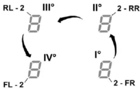
- continuing to hold down (A) press, one at a time, all the areas of Selection/Display (2) of the cooking zones, anti-clockwise starting from the front right zone (FR)
chemical
Chemical reaction diagram showing transformation of 8-digit numbers into 2-RR and 2-FR with labeled angles I°, II°, III°, IV°, FL°, RL°- each press will be accompanied by a short audible signal
- once all the Displays (2) have been pressed, it will be possible to release the key (A)
at this point:
- the Display (2) of the left rear zone (RL) will show in alternate sequence the symbols “C” and “0”, indicating that it is possible to perform the setting: select the Display (2-RL) then scroll on the Selection bar (3), until the symbols “C” and “8”, appear the Display (2-FL) will show the current setting**
$$ \begin{array}{l} 0 = 7. 4 \mathrm{KW} \ 1 = 4. 5 \mathrm{KW} \ 2 = 3. 1 \mathrm{KW} \ \end{array} $$
** by default the setting is 7.4 KW
To change the Power Limitation setting
- press the Display (2) of the left front area (FL) - then scroll on the Selection bar (3), to select the new setting
- to save the choice made, press the Ⓐ ON/OFF key (1), for 2 seconds; a prolonged audible signal will be emitted to confirm the successful setting
Bridge Zones
Thanks to the Bridge function, the cooking zones are able to work in a combined manner, creating a single zone with the same power level. This function allows evenly distributed cooking with large-sized pots and pans.
The front "Master" cooking zone can be used in combination with the corresponding "Secondary" cooking zone at the back
(to check which zones are equipped with this function, see the illustrated part of this manual).
To activate the Bridge Function:
- simultaneously select the two cooking zones you want to use
- the Display (2) of the "Secondary" cooking zone shows the symbol "π"
- using the Selection bar (3), it will be possible to set the Level (Power) of exercise, which will be shown in the Display (2) of the "Master" cooking zone
- to deactivate the Bridge Function simply repeat the same activation procedure
Note: the Cooking Timer Zone, activated during the Bridge Function, causes the automatic shut-down of both cooking zones, as in this case they are considered a single combined area.
USING THE EXTRACTOR FAN
- Switch-on
Press (touch) briefly ON/OFF (1) hob/extractor: the symbol lights up;
continuing to press, all the available functions will become visible for a few moments, e, after which only the main ones will remain active; the others can be used, and will be activated, subsequently, during use of the device.
IMPORTANT:
all the available functions will be illuminated with light intensity, which will become more intense only when they are activated.
Press again to turn off
Note: This function has priority over the others.
- Switching the extractor system off: Open the Flap touch the selection Zone (12) to activate the extractor system.
Note: The extractor zone is fitted with a mechanical rotating FLAP. The FLAP must be opened before switching on the hood to activate the extractor system. The hood has a sensor which when the extractor is on stops the motor automatically if the FLAP is closed. Extraction only starts again when the FLAP is reopened.
● Extraction speed (power):
The extractor is equipped with 3 levels of extraction speed (power)
Touch and slide your fingers along the Selection bar (3):
to the right to increase the level of power; to the left to decrease the level of power.
The power level set will be displayed in the Selection/Display area (12)
● Power Booster
The product has 2 additional power levels (above level 3)
— Power Booster 1 : timed for 15 min.
— Power Booster 2 : timed for 5 min.
after which the power returns to the previously set level.
Touch and slide with the fingers along the Selection bar (3) (over level 3) and activate the Power Booster 1
The Power Booster level 1 is indicated in the Selection / Display area (12) with the number "4" flashing
Touch and slide with the fingers along the Selection bar (3) (over level 3) and activate the Power Booster 2
The Power Booster level 2 is indicated in the Selection / Display area (12) with the symbol" P" flashing
● Automatic operation
The hood will turn on at the most suitable speed, adapting the extraction capacity to the maximum cooking level used in the cooking zone.
When the cooking zones are switched off, the hood adapts its extraction speed, decreasing it gradually, to eliminate residual vapours and odours.
To activate this function:
Press (A) (14)
Repeat the operation to deactivate.
Note: if during automatic operation are selected from the Selection bar (3) the speeds from 1 to 3, the automatic operation is interrupted;
if, instead, the Power Boosters are selected, automatic operation will resume at the end of the timing, while in the meantime the symbol “(A)” remains flashing.
Note: if the hob automatically shuts down with Automatic mode active, the extractor fan will automatically turn off in a gradual manner.
● Filter saturation indicator
The hood indicates when filter maintenance is needed:
Carbon/ceramic odour filters
"FILTER"(13) comes on
Grease filter
"FILTER"(13) flashes
Note: this function is disabled by default (see how to enable it in the paragraph "Activation filter saturation
indicator")
- Reset filter saturation
After performing maintenance on the filters (greases and/or carbon/ceramic), press and hold "FILTER" (13);
"FILTER"(13) turns off, restarting the indicator count.
● Activation filter saturation indicator
This indicator is normally deactivated.
To activate it, proceed as follows:
- turn on the extractor hob via Ⓘ;
- with the extraction motor and cooking zones off, press the
Selection zone (12)
- long press 'HOOD' (11) until the letters "F" - "G" appear alternately flashing in the Display (12)
F = carbon/ceramic odour filters
G = grease filter
Carbon/ceramic odour filters
— press on the Display (12) when the letter "F" appears
- press " FILTER" (13) - flashing light
- long press "HOOD" (11) again to confirm the activation of the carbon/ceramic odour filter indicator
Grease filter
— press on the Display (12) when the letter "G" appears
- press " FILTER" (13) - fixed light
- long press "HOOD" (11) again to confirm activation of the grease filter indicator
Power tables
| Power level | Cooking type | Use of level(display combines the experience and cooking habits) | |
| Max power | Boost | Heat | Ideal to quickly increase the temperature of the food quickly to fast boiling in the case of water or quickly heat cooking liquids |
| 8-9 Fry - boil | Ideal for browning, starting to cook, frying frozen products, boiling rapidly | ||
| High power | 7-8 Brown | - fry - boil - grill | Ideal for frying, keeping the boil, cooking and grilling (for short times, 5-10 minutes) |
| 6-7 Brown | - cook - stew - fry - grill | Ideal for frying, maintaining a simmer, cooking and grilling (for average times, 10-20 minutes), preheating accessories | |
| Medium power | 4-5 Cook | - stew - fry - grill | Ideal for stewing, maintaining a light boil, cooking (for longer times). Stir pasta |
| 3-4 Cook | - simmer - thicken - stir | Ideal for slow cooking (rice, sauces, roasts, fish) in the presence of liquid (e.g. water, wine, broth, milk), stirring pasta | |
| 2-3 Cook | - simmer - thicken - stir | Ideal for slow cooking (volume less than one litre: rice, sauces, roasts, fish) in the presence of liquid (e.g. water, wine, broth, milk) | |
| Low power | 1-2 Melt - thaw - keep warm - stir | Ideal for softening butter, gently melting chocolate, thawing small products | |
| 1 Melt - thaw - keep warm - stir | Ideal for keeping small portions of freshly cooked food warm or keeping the temperature of serving dishes and stirring risotto | ||
| OFF | Zero power Support surface | Hob in stand-by or off (possible presence of residual heat from the end of cooking, signalled by H-L-O) | |
4. Maintenance
Caution! Before any cleaning or maintenance, make sure the cooking zones are switched off and the heat indicator has turned off.
Hob maintenance
Cleaning
The hob must be cleaned after each use.
Important: Do not use abrasive sponges or pads, they may ruin the glass. Do not use irritant chemical detergents such as oven sprays or stain removers. After each use, let the hob cool down completely to remove encrusted on dirt and stains. Use a soft cloth, paper towel or specific products to clean the hob (follow the Manufacturer's instructions).
DO NOT USE STEAM JET CLEANERS!!!
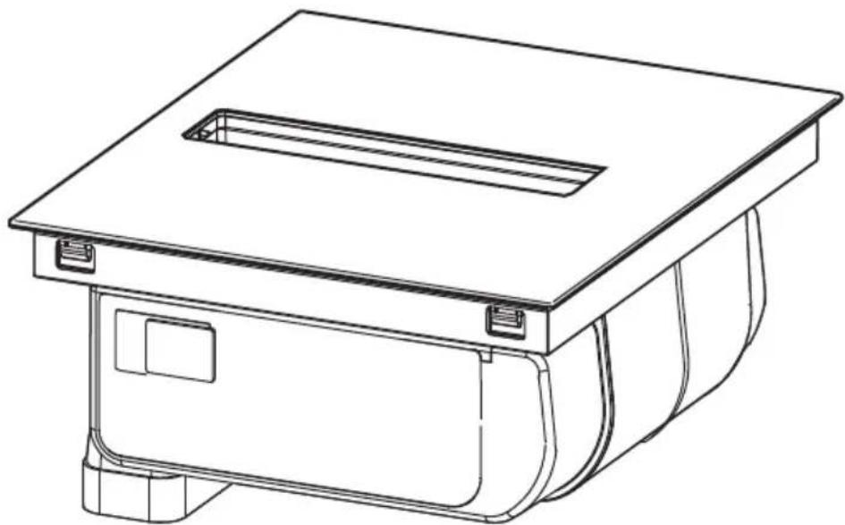
Important: In the event of the accidental spillage of large quantities of liquid from pans it is possible to drain by using the discharge valve, on the lower section of the product, in order to remove any residues and ensuring maximum hygiene levels are maintained. Fig. 16
Extractor fan maintenance
Cleaning
For cleaning, use ONLY a cloth moistened with neutral liquid detergents. DO NOT USE CLEANING UTENSILS OR TOOLS!
Avoid the use of products containing abrasives.
DO NOT USE ALCOHOL!
Cleaning the metal grille:
The grille must be washed by hand with hot water and neutral detergent, then dried thoroughly to prevent oxidation.
Grease filter
Traps grease particles generated by cooking.
Must be cleaned once per month (or when the filter saturation indication system indicates this need), with non-aggressive detergents, either manually or in the dishwasher at a low temperature and in a short cycle.
When cleaned in the dishwasher, the metal grease filter may discolour, but its filtering characteristics remain unchanged.
Fig. 15.1.2 - 15.2.3
Activated Carbon Filter - Ceramic
(Only for Filtration Version)
Traps unpleasant odours generated by cooking.
The product comes with a set of odour filters. The saturation of the odour filters can occur after somewhat prolonged use depending on the type of cooking and how regularly the grease filter is cleaned. The odour filters can be thermally regenerated every 2/3 months in an oven pre-heated to 200^ C for 45 minutes. The correct regeneration of the filter ensures that it can constantly filter efficiently for 5 years.
Warning! Do not leave filters on the bottom of the oven, but place it on a baking tray and position it at a mid height..
Fig. 15.2.1
Troubleshooting
| ERROR CODE DESCRIPTION POSSIBLE CAUSES ERROR REMOVAL | |||
| E2 | The command zone switches off due to an excessively high temperature | The temperature inside the electronic parts is too high | Wait for the hob to cool before reusing it |
| E3 Container unsuitable | Loss of magnetic properties | Remove the pot | |
| E5 | Communication problems between the user interface and induction module | Electricity is not reaching the module; The power cable is incorrectly connected or faulty | Disconnect the hob from the electrical network and check the connection |
| For all other error signals ( E ... U ... C ... ) | Call customer service and report the error code | ||
Customer service
Before contacting Customer Service
-
Check that you cannot solve the problem yourself based on the points described in "Troubleshooting".
-
Switch the device off and on again to see if the problem resolves itself.
If the fault persists after the above checks, contact the nearest Customer Service.
DE
natural_image
Illustration of kitchenware including a flat plate, a pan with a lid, and a pot (no text or symbols)NEIN!
natural_image
Two grayscale illustrations of cooking utensils: a flat pan with a side dish and a closed pan with a circular cutter head (no text or symbols)NEIN!
natural_image
Illustration of a frying pan and its side view showing the exterior (no text or symbols)JA!
text_image
RL FL RR FR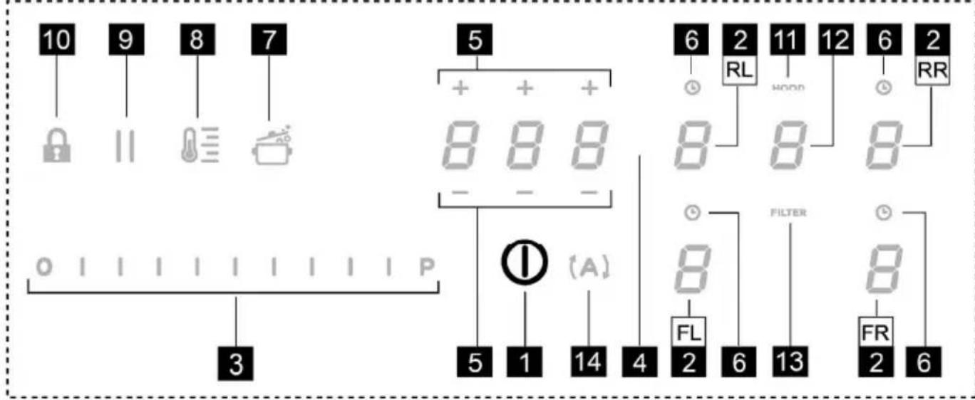
text_image
10 9 8 7 5 + + + 8 8 8 - 6 2 RL HOOD 11 12 6 2 RR 8 8 8 ① (A) 5 1 14 4 FL 2 6 FILTER 13 8 FR 2 6 3● Temperature Manager (Warming Function)
chemical
Chemical reaction diagram showing transformation of compounds III° and IV° into II° and I° with labeled positions and directional arrows$$ 0 = 7, 4 \mathrm{KW} $$
$$ 1 = 4, 5 \mathrm{KW} $$
$$ 2 = 3, 1 \mathrm{KW} $$
natural_image
Illustration of kitchenware including a plate with lid and a pot with lid (no text or symbols)NON!
natural_image
Two grayscale illustrations of cooking utensils: a flat pan with a side panel and a closed pan with a circular vent (no text or symbols)NON!
natural_image
Illustration of a pan and its cooking pan (no text or symbols)OUI!
text_image
RL FL RR FR
text_image
10 9 8 7 5 + + + 8 8 8 - - 6 2 RL HOOD 11 12 6 2 RR 8 8 8 ① (A) 5 1 14 4 FL 2 6 FILTER 13 8 FR 2 6chemical
Chemical reaction diagram showing transformation of compounds III° and IV° into II° and I° with labeled positions and directional arrows$$ 0 = 7, 4 \mathrm{KW} $$
$$ 1 = 4, 5 \mathrm{KW} $$
$$ 2 = 3, 1 \mathrm{KW} $$
natural_image
Illustration of kitchenware including a cooking pan, lid, and pot (no text or symbols)NEE!
natural_image
Two kitchen utensils: a flat pan with a side panel and a closed pan with a circular lid (no text or symbols visible)NEE!
natural_image
Illustration of a frying pan and its side view showing the exterior (no text or symbols)JA!
text_image
RL FL RR FR
text_image
10 9 8 7 5 + + + 8 8 8 - - 6 2 11 12 6 2 RR RL HOOD 8 8 8 ① (A) 5 1 14 4 FL 2 6 13 8 FILTER FR 2 6● Residual Heat Indicator [Indicator restwarmte]
- selecteer Zone/Display (4)
chemical
Chemical reaction diagram showing transformation of compounds III° and IV° into II° and I° with labeled positions and rotation directions● Indicator verzadiging filters
● Activering indicator verzadiging filters
natural_image
Illustration of kitchenware including a plate with a cross symbol, a pan with a lid, and a pot (no text or symbols)¡NO!
natural_image
Two grayscale illustrations of cooking utensils: a flat pan with a lid and a side pan with a circular cutter head (no text or symbols)¡NO!
natural_image
Illustration of a frying pan and its side view showing the exterior (no text or symbols)¡sí!
text_image
RL FL RR FR
text_image
10 9 8 7 5 + + + 8 8 8 - - 6 2 RL HOOD 11 12 6 2 RR 8 8 8 ① (A) 5 1 14 4 FL 2 6 FILTER 13 8 FR 2 6Teclas táctiles (TOUCH)/Pantala
chemical
Chemical reaction diagram showing transformation of compounds III° and IV° into II° and I° with labeled positions and rotation directionsnatural_image
Illustration of kitchenware including a cooking pan, a lid with a pot, and a side dish (no text or symbols)NÃO!
natural_image
Two black frying pan illustrations, one with a side panel and the other with a side pan (no text or symbols visible)NÃO!
natural_image
Illustration of a pan and its cooking pan (no text or symbols)SIM!
text_image
RL FL RR FR
text_image
10 9 8 7 5 + + + 8 8 8 - - 6 2 RL HOOD 11 12 6 2 RR 8 8 8 ① (A) 5 1 14 4 FL 2 6 FILTER 13 8 FR 2 6Botões de toque (TOUCH) /Visor
● Residual Heat Indicator (Indicador Calor Residual)
chemical
Chemical reaction diagram showing transformation of compounds III° and IV° into II° and I° with labeled positions and directional arrows$$ 0 = 7, 4 \mathrm{KW} $$
$$ 1 = 4, 5 \mathrm{KW} $$
$$ 2 = 3, 1 \mathrm{KW} $$
natural_image
Illustration of kitchenware including a plate with a lid and a pot (no text or symbols)OXI!
natural_image
Two grayscale illustrations of cooking utensils: a flat pan with a circular lid and a side pan with a griddle (no text or symbols)OXI!
natural_image
Illustration of a frying pan and its side view showing the exterior (no text or symbols)NAI!
text_image
RL FL RR FR
text_image
10 9 8 7 5 + + + 8 8 8 - - 6 2 RL HOOD 11 12 6 2 RR 8 8 8 ① (A) 5 1 14 4 FL 2 6 FILTER 13 8 FR 2 6chemical
Chemical reaction diagram showing transformation of 8-digit numbers into 2-RR and 2-FR with labeled angles (III°, IV°, I°)● Bridge Zones [Zώνες Γέφυρας]
natural_image
Illustration of kitchenware including a plate with a lid and a pot with a lid (no text or symbols)NEJ!
natural_image
Two black-and-white photos of frying panes with handles and a side view showing interior (no text or symbols)NEJ!
natural_image
Illustration of a frying pan and its side view showing the exterior (no text or symbols)JA!
text_image
RL FL RR FR
text_image
10 9 8 7 5 + + + 8 8 8 - - 6 2 RL HOOD 11 12 6 2 RR 8 8 8 ① (A) 5 1 14 4 FL 2 6 FILTER 13 8 FR 2 6Touch-knappar/Display
● Key Lock (Knapplås)
chemical
Chemical reaction diagram showing transformation of 8-digit numbers into 2-RR and 2-FR with labeled angles I°, II°, III°, IV°, FL°, RL°$$ 0 = 7, 4 \mathrm{KW} $$
$$ 1 = 4, 5 \mathrm{KW} $$
$$ 2 = 3, 1 \mathrm{KW} $$
natural_image
Illustration of kitchenware including a plate with a lid and a pan with a lid (no text or symbols)EI!
natural_image
Two grayscale illustrations of cooking utensils: a flat pan with a lid and a side pan with a grater (no text or symbols visible)El!
natural_image
Illustration of a frying pan and its side view showing the exterior (no text or symbols)KYLLÄ!
text_image
RL FL RR FR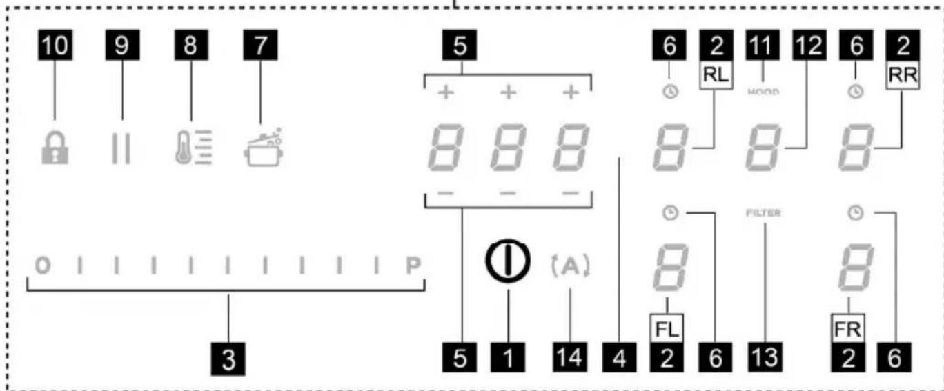
text_image
10 9 8 7 5 6 2 11 12 6 2 RL HOOD RR 8 8 8 ① (A) 5 1 14 4 FL FILTER 8 2 6 13 8 FR 2 6chemical
Chemical reaction diagram showing transformation of 8-digit numbers into 2-RR and 2-FR with labeled angles (III°, IV°, I°)$$ 0 = 7, 4 \mathrm{KW} $$
$$ 1 = 4, 5 \mathrm{KW} $$
$$ 2 = 3, 1 \mathrm{KW} $$
natural_image
Illustration of kitchenware including a plate with a lid and a pan with a lid (no text or symbols)NEI!
natural_image
Two black-and-white illustrations of frying panes with handles, one showing a side dish and the other showing a circular opening (no text or symbols)NEI!
natural_image
Illustration of a frying pan and its side view showing the exterior (no text or symbols)JA!
Viktig: Ikke sett varme kjeler på overflaten til platetoppens kontrollpanel.
text_image
RL FL RR FR
text_image
10 9 8 7 5 + + + 8 8 8 - - 6 2 RL HOOD 11 12 6 2 RR 8 8 8 ① (A) 5 1 14 4 FL 2 6 FILTER 13 8 FR 2 6Berøringstaster (TOUCH) / Display
Display for kokesoner
● Safe Activation (sikker igangsetting)
Produktet aktiveres kun när det finnes kjeler/gryter plassert på sonene. Oppvarmingsfasen vil ikke starte opp (eller den avbrytes) hvis det ikke finnes gryter på platen.
● Residual Heat Indicator (restvarmeindikator)
● Power Booster (forsterkernivå)
Produktet er utstyrt med et ekstra effektnivå (over nivået som forblir aktivt i 5 minutter før effektnivået går tilbake til forrige nivå.
● Key Lock (Tastelås)
chemical
Chemical reaction diagram showing transformation of 8-digit numbers into 2-RR and 2-FR with labeled angles (III°, IV°, I°)- hver gang man trykker vil det skilles ut et kort akustisk signal - när man har trykket på alle Display (2), er det mulig å slippe opp tasten (A)
Følgende skjer:
$$ 0 = 7, 4 \mathrm{KW} $$
$$ 1 = 4, 5 \mathrm{KW} $$
$$ 2 = 3, 1 \mathrm{KW} $$
** standard innstilling er 7,4 KW
natural_image
Illustration of kitchenware including a plate with a lid and a pan with a lid (no text or symbols)NEJ!
natural_image
Two grayscale illustrations of cooking utensils: a flat pan with a side panel and a closed pan with a circular lid (no text or symbols)NEJ!
natural_image
Illustration of a frying pan and its side view showing the exterior (no text or symbols)JA!
text_image
RL FL RR FR
text_image
10 9 8 7 5 + + + 8 8 8 - - 6 2 RL HOOD 11 12 6 2 RR 8 8 8 ① (A) 5 1 14 4 FL 2 6 13 FILTER 8 FR 2 6Berøringsknapper (TOUCH) / display
● Safe Activation (Sikker aktivering)
● Key Lock (Tastblokering)
chemical
Chemical reaction diagram showing transformation of 8-digit numbers into 2-RR and 2-FR with labeled angles (III°, IV°, I°)$$ 0 = 7, 4 \mathrm{KW} $$
$$ 1 = 4, 5 \mathrm{KW} $$
$$ 2 = 3, 1 \mathrm{KW} $$
natural_image
Illustration of kitchenware including a plate, cooking pan, and pot (no text or symbols)natural_image
Two cooking panes with handles, one showing a side dish and the other showing a side dish (no text or symbols on the pan surfaces)natural_image
Illustration of a frying pan and its side view showing the exterior (no text or symbols)text_image
RL FL RR FR
text_image
10 9 8 7 5 + + + 8 8 8 - - 6 2 RL HOOD 11 12 6 2 RR 8 8 8 ① (A) 5 1 14 4 FL 2 6 FILTER 13 8 FR 2 6chemical
Chemical reaction diagram showing transformation of 8-digit numbers into 2-RR and 2-FR with labeled angles I°, II°, III°, IV°, FL°, RL°$$ 0 = 7, 4 \mathrm{KW} $$
$$ 1 = 4, 5 \mathrm{KW} $$
$$ 2 = 3, 1 \mathrm{KW} $$
natural_image
Illustration of kitchenware including a plate with a lid and a pan with a lid (no text or symbols)NE!
natural_image
Two grayscale illustrations of cooking utensils: a flat pan with a side dish and a closed pan with a circular cutter (no text or symbols)NE!
natural_image
Illustration of a frying pan and its side view showing the exterior (no text or symbols)ANO!
text_image
RL FL RR FR
text_image
10 9 8 7 5 + + + 8 8 8 - - 6 2 RL HOOD 11 12 6 2 RR 8 8 8 ① (A) 5 1 14 4 FL 2 6 13 FILTER 8 FR 2 6chemical
Chemical reaction diagram showing transformation of 8-digit numbers into 2-RR and 2-FR with labeled angles I°, II°, III°, IV°, FL°, RL°$$ 0 = 7, 4 \mathrm{KW} $$
$$ 1 = 4, 5 \mathrm{KW} $$
$$ 2 = 3, 1 \mathrm{KW} $$
natural_image
Illustration of kitchenware including a plate with lid and a pan with lid (no text or symbols)NIE!
natural_image
Two grayscale illustrations of cooking utensils: a flat pan with a side dish and a closed pan with a circular cutter (no text or symbols)NIE!
natural_image
Illustration of a frying pan and its side view showing the exterior (no text or symbols)ÁNO!
text_image
RL FL RR FR
text_image
10 9 8 7 5 + + + 8 8 8 - - 6 2 RL HOOD 11 12 6 2 RR 8 8 8 ① (A) 5 1 14 4 FL 2 6 13 FILTER 8 FR 2 6Dotykové tlačidlá (TOUCH) / Displej
chemical
Chemical reaction diagram showing transformation of 8-fluorouracil (RL-2) to 8-fluorouracil (FL-2) with labeled angles and intermediates$$ 0 = 7, 4 \mathrm{kW} $$
$$ 1 = 4, 5 \mathrm{kW} $$
$$ 2 = 3, 1 \mathrm{kW} $$
* predvolené nastavenie je 7,4 kW
natural_image
Illustration of kitchenware including a pan, lid, and cooking pot (no text or symbols)NEM!
natural_image
Two grayscale illustrations of cooking utensils, one with a lid and handle, the other showing a pan with a circular pattern (no text or symbols)NEM!
natural_image
Illustration of a frying pan and its side view showing the exterior (no text or symbols)IGEN!
text_image
RL FL RR FR
text_image
10 9 8 7 5 + + + 8 8 8 - - 6 2 RL HOOD 11 12 6 2 RR 8 8 8 ① (A) 5 1 14 4 FL 2 6 FILTER 13 8 FR 2 6chemical
Chemical reaction diagram showing transformation of 8-fluoro-2,4-tris(1,2,3-tris(1,2,3-tris(1,2,3-tris(1,2,3-tris(1,2,3-tris(1,2,3-tris(1,2,3-tris(1,2,3-tris(1,2,3-tris(1,2,3-tris(1,2,3-tris(1,2,3-tris(1,2,3-tris(2,2,3,3,4-tris(1,2,3,4-tris(1,2,3,4-tris(1,2,3,4-tris(1,2,3,4-tris(1,2,3,4-tris(1,2,3,4-tris(1,2,3,4-tris(1,2,3,4-tris(1,2,3,4-tris(1,2,3,4-tris(1,0) and 2-RR), 2-FR))$$ 0 = 7, 4 \mathrm{KW} $$
$$ 1 = 4, 5 \mathrm{KW} $$
$$ 2 = 3, 1 \mathrm{KW} $$
natural_image
Illustration of kitchenware including a cooking pan, a pot, and a lid (no text or symbols)HE!
natural_image
Two grayscale illustrations of frying panes with different interior designs (no text or symbols)HE!
natural_image
Illustration of a frying pan and its side view showing the exterior (no text or symbols)ДА!
text_image
RL FL RR FR
text_image
10 9 8 7 5 + + + 8 8 8 - - 6 2 RL HOOD 11 12 6 2 RR 8 8 8 ① (A) 5 1 14 4 FL 2 6 FILTER 13 8 FR 2 6Сензорни бутони (TOUCH) / Дисплей
$$ 0 = 7, 4 \mathrm{KW} $$
$$ 1 = 4, 5 \mathrm{KW} $$
$$ 2 = 3, 1 \mathrm{KW} $$
natural_image
Illustration of kitchenware including a cooking pan, lid, and pot (no text or symbols)NU!
natural_image
Two black-and-white illustrations of frying panes with handles, one showing a side dish and the other showing a circular interior (no text or symbols)natural_image
Illustration of a frying pan and its side view showing the exterior (no text or symbols)DA!
text_image
RL FL RR FR
text_image
10 9 8 7 5 + + + 8 8 8 - - 6 2 RL HOOD 11 12 6 2 RR 8 8 8 ① (A) 5 1 14 4 FL 2 6 FILTER 13 8 FR 2 6Taste tactile (TOUCH) / Afşaj
chemical
Chemical reaction diagram showing transformation of 8-digit numbers into 2-RR and 2-FR with labeled angles I°, II°, III°, IV°, FL°, RL°$$ 0 = 7, 4 \mathrm{KW} $$
$$ 1 = 4, 5 \mathrm{KW} $$
$$ 2 = 3, 1 \mathrm{KW} $$
natural_image
Illustration of kitchenware including a plate with a lid and a pan with a lid (no text or symbols)HET!
natural_image
Two grayscale illustrations of frying panes with different interior designs (no text or symbols)HET!
natural_image
Illustration of a frying pan and its side view showing the exterior (no text or symbols)ДА!
text_image
RL FL RR FR
text_image
10 9 8 7 5 + + + 8 8 8 - - 6 2 RL HOOD 11 12 6 2 RR 8 8 8 ① (A) 5 1 14 4 FL 2 6 FILTER 13 8 FR 2 6natural_image
Illustration of cooking utensils including a pan, lid, and pot (no text or symbols)natural_image
Two kitchen utensils: a flat pan with a side panel and a closed pan with a circular lid, both open (no text or symbols visible)natural_image
Illustration of a frying pan and its side view showing the exterior (no text or symbols)TAK!
text_image
RL FL RR FR
text_image
10 9 8 7 5 + + + 8 8 8 - - 6 2 RL HOOD 11 12 6 2 RR 8 8 8 ① (A) 5 1 14 4 FL 2 6 FILTER 13 8 FR 2 6chemical
Chemical reaction diagram showing transformation of 8-digit numbers into 2-RR and 2-FR with labeled angles (III°, IV°, I°)natural_image
Illustration of kitchenware including a plate with lid and a pan with lid (no text or symbols)natural_image
Two black-and-white illustrations of frying panes with handles and a side panel showing interior design (no text or symbols)БОЛМАЙДЫ!
natural_image
Illustration of a frying pan and its side view showing the lid and pan (no text or symbols)БОЛАДЫ!
text_image
RL FL RR FR
text_image
10 9 8 7 5 + + + 8 8 8 - - 6 2 RL HOOD 11 12 6 2 RR 8 8 8 ① (A) 5 1 14 4 FL 2 6 FILTER 13 8 FR 2 6Сенсорлы түймелер (TOUCH) / Дисплей
chemical
Chemical reaction diagram showing transformation of 8-fluoro-2,4-tris(4-methyl)oxalate to 8-fluoro-2,4-tris(4-methyl)oxalate via intermediate I° and II°natural_image
Illustration of kitchenware including a cooking pan, lid, and pot (no text or symbols)El!
natural_image
Two grayscale illustrations of frying panes with handles, one showing a side dish and the other showing a circular pattern (no text or symbols)El!
natural_image
Illustration of a frying pan and its side view showing the exterior (no text or symbols)JAH!
text_image
RL FL RR FR
text_image
10 9 8 7 5 + + + 8 8 8 - - 6 2 RL HOOD 11 12 6 2 RR 8 8 8 ① (A) 5 1 14 4 FL 2 6 13 FILTER 8 FR 2 6chemical
Chemical reaction diagram showing transformation of 8-digit numbers into 2-RR and 2-FR with labeled angles (III°, IV°, I°)$$ \begin{array}{l} 0 = 7, 4 \mathrm{kW} \ 1 = 4, 5 \mathrm{kW} \ 2 = 3, 1 \mathrm{kW} \ \end{array} $$
** Vaikeseadistus on 7,4 kW.
natural_image
Illustration of kitchenware including a plate with a lid and a pan with a lid (no text or symbols)NE!
natural_image
Two grayscale illustrations of cooking utensils: a flat pan with a side dish and a closed pan with a circular cutter (no text or symbols)NE!
natural_image
Illustration of a frying pan and its side view showing the exterior (no text or symbols)TAIP!
text_image
RL FL RR FR
text_image
10 9 8 7 5 + + + 8 8 8 - - 6 2 11 12 6 2 RR RL HOOD 8 8 8 ① (A) 5 1 14 4 FL 2 6 13 FILTER 8 FR 2 6chemical
Chemical reaction diagram showing transformation of 8-digit numbers into 2-RR and 2-FR with labeled angles I°, II°, III°, IV°, FL°, RL°$$ 0 = 7, 4 \mathrm{KW} $$
$$ 1 = 4, 5 \mathrm{KW} $$
$$ 2 = 3, 1 \mathrm{KW} $$
natural_image
Illustration of kitchenware including a cooking pan, a lid with a cross symbol, and a pot (no text or labels)NÊ!
natural_image
Two grayscale illustrations of frying panes with different interior designs (no text or symbols)NÊ!
natural_image
Illustration of a frying pan and its side view showing the exterior (no text or symbols)JĀ!
text_image
RL FL RR FR
text_image
10 9 8 7 5 + + + 8 8 8 - - 6 2 RL HOOD 11 12 6 2 RR 8 8 8 ① (A) 5 1 14 4 FL 2 6 FILTER 13 8 FR 2 6chemical
Chemical reaction diagram showing transformation of 8-digit numbers into 2-RR and 2-FR with labeled angles I°, II°, III°, IV°, FL°, RL°$$ 0 = 7, 4 \mathrm{KW} $$
$$ 1 = 4, 5 \mathrm{KW} $$
$$ 2 = 3, 1 \mathrm{KW} $$
natural_image
Illustration of kitchenware including a plate with lid and a pan with lid (no text or symbols)NE!
natural_image
Two grayscale illustrations of frying panes with different interior designs (no text or symbols)NE!
- Dno koje nije ravno ili je sa hrapavom površinom.
natural_image
Illustration of a frying pan and its side view showing the exterior (no text or symbols)DA!
Važno: nikada ne stavljajte vruće lonce i tave na površinu kontrolne ploče.
Postojeće posude
Možete proveriti da li je materijal od kojeg je proizvedena vaša posuda magnetski ili ne, upotrebom jednostavnog magneta. Posude nisu pogodne za upotrebu ako se ne mogu magnetski detektovati. Uputstva iz prethodnog stava se takođe primjenjuju i u ovom slučaju.
Preporučeni dijametri dna posuda
text_image
RL FL RR FR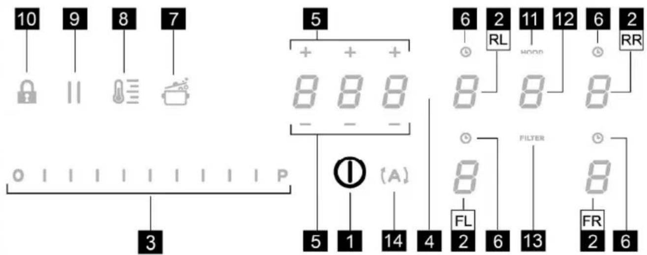
text_image
10 9 8 7 5 + + + 8 8 8 - - 6 2 RL HOOD 11 12 6 2 RR 8 8 8 ① (A) 5 1 14 4 FL 2 6 13 FILTER 8 FR 2 6Tasteri osetljivi na dodir (TOUCH) / displej
● Power Level (nivo snage)
chemical
Chemical reaction diagram showing transformation of 8-digit numbers into 2-RR and 2-FR with labeled angles I°, II°, III°, IV°, FL°, RL°- svaki put kad pritisnete, emituje se kratki zvučni signal
$$ 0 = 7, 4 \mathrm{KW} $$
$$ 1 = 4, 5 \mathrm{KW} $$
$$ 2 = 3, 1 \mathrm{KW} $$
** zadana postavka je 7,4 KW
Za promenu podešavanja funkcije Power Limitation (ograničenje snage)
- pritisnite Display (displej) (2) prednje leve zone (FL)
NEMOJTE KORISTITI ALKOHOL!
natural_image
Illustration of cooking utensils including a pan, lid, and pot (no text or symbols)NE!
- da dno ne vsebuje aluminija: posoda se ne segreva ker induktorji morda je niti ne prepoznajo.
natural_image
Two grayscale illustrations of frying panes with different interior designs (no text or symbols)NE!
- da dna niso položna ali so z grobo površino.
natural_image
Illustration of a frying pan and its side view showing the exterior (no text or symbols)DA!
text_image
RL FL RR FR
text_image
10 9 8 7 5 + + + 8 8 8 - - 6 2 RL HOOD 11 12 6 2 RR 8 8 8 ① (A) 5 1 14 4 FL 2 6 13 FILTER 8 FR 2 6Tipke na dotik (TOUCH) / Zaslon
● Pot Detector (Zaznava posode)
chemical
Chemical reaction diagram showing transformation of 8-digit numbers into 2-RR and 2-FR with labeled angles I°, II°, III°, IV°, FL°, RL°$$ 0 = 7, 4 \mathrm{kW} $$
$$ 1 = 4, 5 \mathrm{KW} $$
$$ 2 = 3, 1 \mathrm{KW} $$
natural_image
Illustration of kitchenware including a pan, lid, and pot (no text or symbols)NE!
- Dno ne smije sadržavati aluminij: posuđe se ne zagrijava i induktori ne mogu prepoznati takvo posuđe.
natural_image
Two grayscale illustrations of frying panes with different interior designs (no text or symbols)NE!
- Dna koja nisu ravna ili su s hrapavom površinom. Oduzimaju kontaktnu površinu između induktora i posuđe, smanjujući učinkovitost i pogoršavajući iskustvo kuhanja.
natural_image
Illustration of a frying pan and its side view showing the exterior (no text or symbols)DA!
text_image
RL FL RR FR
text_image
10 9 8 7 5 + + + 8 8 8 - - 6 2 RL HOOD 11 12 6 2 RR 8 8 8 ① (A) 5 1 14 4 FL 2 6 FILTER 13 8 FR 2 6Dodirne tipke (TOUCH) / Zaslon
- ON/OFF (UKLJ/ISKLJ) ploče za kuhanje/usisnog sustava
- Odabir zone za kuhanje / Zaslon zone za kuhanje
- Povećanje/Smanjenje razine snage kuhanja i brzine (snage) usisa
Prikaz razine snage kuhanja i brzine (snage) usisa
● Power Level (Razina snage)
Ploča za kuhanje ima 9 razina snage
Dodirnite i klizite prstima po Traci za odabir (3):
chemical
Chemical reaction diagram showing transformation of 8-digit numbers into 2-RR and 2-FR with labeled angles (III°, IV°, I°)- pri svakom pritisku, oglašava se zvučni signal
- kada se pritisnu svi Display (zasloni) (2), tipka se može otpustiti (A)
u tom trenutku:
$$ 0 = 7, 4 \mathrm{KW} $$
$$ 1 = 4, 5 \mathrm{KW} $$
$$ 2 = 3, 1 \mathrm{KW} $$
** zadana postavka je 7,4 KW
Za promjenu postavki Power Limitation (ograničenje snage)
- pritisnite Display (zaslon) (2) lijeve prednje zone (FL)
- zatim klizite po Traci za odabir (3), za unošenje novih postavki
- za spremanje odabira pritisnite tipku ON/OFF (UKLJ/ISKLJ) (1), 2 sekunde; u znak potvrde uspješnog podešavanja oglasit će se dugotrajni zvučni signal
● Bridge Zones (most područja)
Zone kuhanja zahvaljujući funkciji Bridge, mogu raditi u kombiniranom načinu, stvarajući jedinstvenu zonu kuhanja s istom razinom snage. Ta funkcija omogućuje ujednačeno kuhanje i s posudama velikih dimenzija.
Može se koristiti u kombinaciji prednja zona za kuhanje "Master" sa odgovarajućom stražnjom zonom za kuhanje "Sekundarna"
NEMOJTE KORISTITI ALKOHOL!
natural_image
Illustration of kitchenware including a plate with lid, a pan with lid, and a pot (no text or symbols)HAYIR!
natural_image
Two grayscale illustrations of frying panes with different interior designs (no text or symbols)HAYIR!
natural_image
Illustration of a frying pan and its side view showing the exterior (no text or symbols)EVET!
text_image
RL FL RR FR
text_image
10 9 8 7 5 + + + 8 8 8 - - 6 2 RL HOOD 11 12 6 2 RR 8 8 8 ① (A) 5 1 14 4 FL 2 6 FILTER 13 8 FR 2 6Dokunmatik tuşlar (TOUCH) / Ekran
● Safety Shut Down (Emniyetli Kapatma)
chemical
Chemical reaction diagram showing transformation of compounds III° and IV° into II° and I° with labeled positions and rotation directionschemical
Chemical reaction diagram showing transformation of 8-digit numbers into 2-RR and 2-FR with labeled angles (III°, IV°, I°)text_image
RL FL RR FR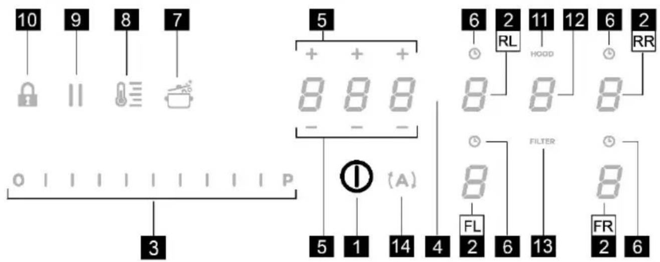
text_image
10 9 8 7 5 + + + 8 8 8 - - 6 2 RL HOOD 11 12 6 2 RR 0 | | | | | | | | | | | | P ① (A) 5 1 14 4 FL 2 6 13 FILTER 8 FR 2 6natural_image
Two grayscale illustrations of cooking utensils: a flat pan with a side dish and a closed pan with a flower-shaped lid (no text or symbols)natural_image
Illustration of a frying pan and its side view showing the lid and handle (no text or symbols)natural_image
Illustration of cooking utensils including a pan, lid, and pot (no text or symbols)natural_image
Pure geometric diagram of a trapezoidal structure with no text, numbers, or symbols
natural_image
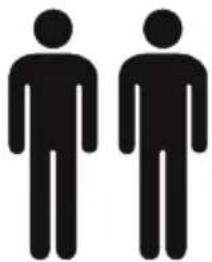
Two identical black silhouette figures of men, no text or symbols present
natural_image
Simple line drawing of two hands with fingers spread (no text or symbols)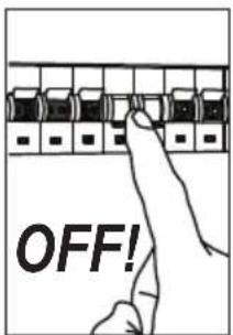
text_image
OFF!
natural_image
Technical line drawing of a saw blade, a rectangular tool holder, and a flat blade (no text or symbols)
natural_image
Illustration of two types of medical or industrial tools: a tape measure and a syringe (no text or symbols present)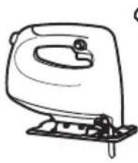
natural_image
Line drawing of a mechanical device with handle and base (no text or symbols)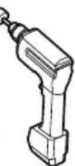
natural_image
Simple line drawing of an open cardboard box (no text or symbols)
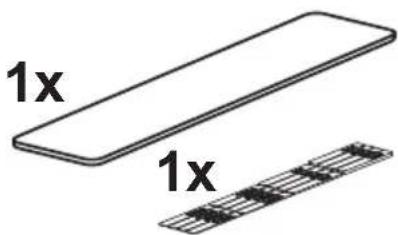
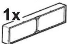
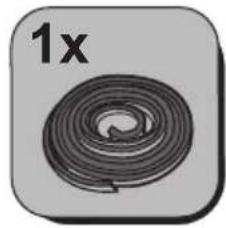
1x
2,8 m
text_image
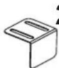
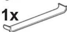
1x 1x*
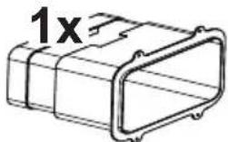

2x
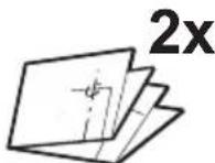
2x
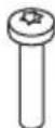
M4x20mm

2x
ø3,5x13mm

www.elica.com
www.shop.elica.com
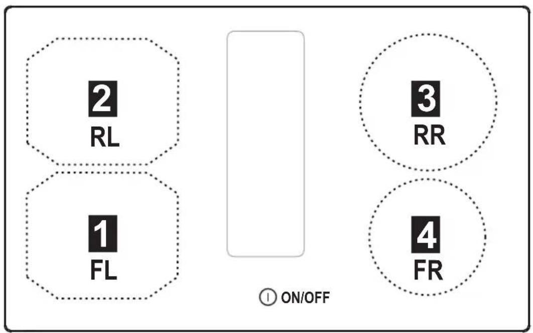
flowchart
graph TD
    A["2 RL"] --> B["1 FL"]
    C["3 RR"] --> D["4 FR"]
    style A fill:#f9f,stroke:#333
    style B fill:#f9f,stroke:#333
    style C fill:#f9f,stroke:#333
    style D fill:#f9f,stroke:#333
    subgraph ON/OFF
        direction LR
        ① ON/OFF
    end
FRONT
other
| Group | Method | Min Power (kw) | Max Power (kw) | |-------|--------|----------------|----------------| | 1 | 1 | 1 | 1 | | 1 | 2 | 1 | 1 | | 1 | 3 | 1 | 1 | | 2 | 1 | 1 | 1 | | 2 | 2 | 1 | 1 | | 2 | 3 | 1 | 1 | | 3 | 1 | 1 | 1 | | 3 | 2 | 1 | 1 | | 3 | 3 | 1 | 1 | | 3 | 4 | 1 | 1 | | 4 | 1 | 1 | 1 | | 4 | 2 | 1 | 1 | | 4 | 3 | 1 | 1 | | 4 | 4 | 1 | 1 |

www.elica.com www.shop.elica.com
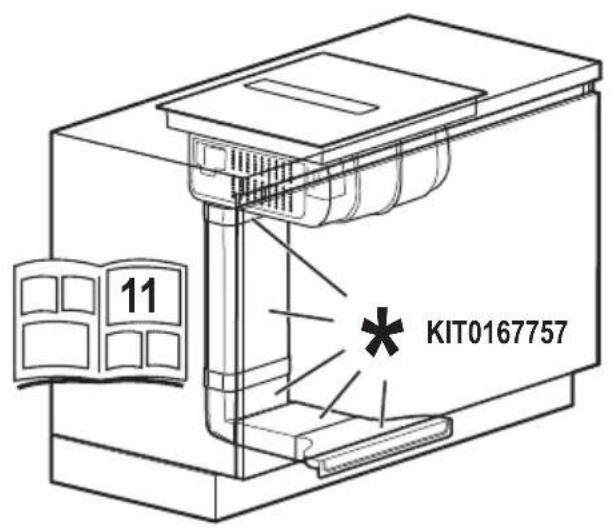
KIT0167756
natural_image
Technical line drawings of various mechanical components and parts, including a 3D block, cylindrical part, bracket, and L-shaped component (no text or symbols present)KIT0167757
natural_image
Technical line drawings of various mechanical components and parts, including L-shaped pipes, rectangular blocks, and a bracket (no text or symbols present)KIT0180522
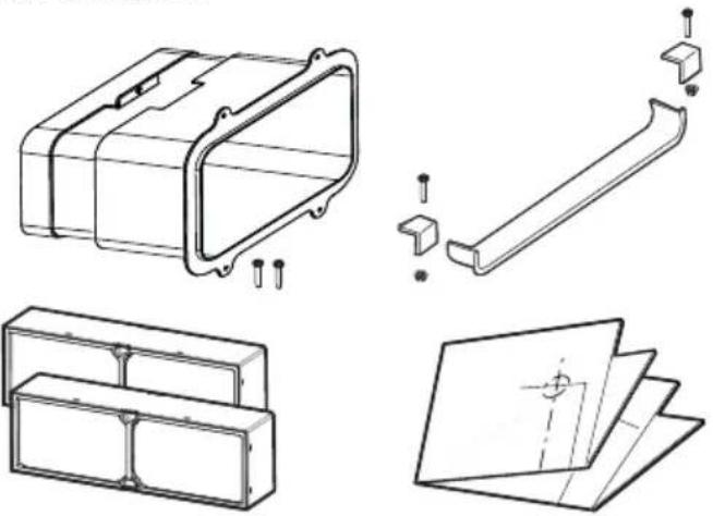
natural_image
Technical line drawings of mechanical components including a housing, bracket, and folded paper (no text or symbols)KIT0167755
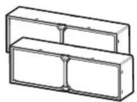
natural_image
3D line drawing of two stacked rectangular blocks with internal divisions (no text or symbols)

www.elica.com www.shop.elica.com
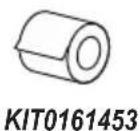
KIT0161453
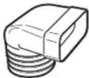
KIT0121005 90° 227x94mm
KIT0121017 218x55mm
KIT0121001 227x94x80mm
KIT0121015 223x59x72mm
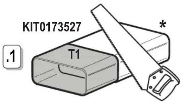
KIT0173527 222x89x500mm
KIT0120991 222x89x1000mm
KIT0121016 90° 218x55mm
KIT0121002 15° 227x94mm
KIT0126810 227x94mm
KIT0168750
KIT0121012 218x55x500mm
KIT0121013 218x55x1000mm

www.elica.com www.shop.elica.com
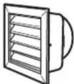
KIT0121007 227x94 Ø146mm
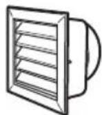
KIT0121010 190x190 Ø147mm
KIT0121009 INT 216x82mm EXT 290x160mm
KIT0121006 90°
KIT0121001 227x94x80mm
KIT0126810 227x94mm
KIT0121003 Ø158 59mm
KIT0173527 222x89x500mm KIT0120991 222x89x1000mm
KIT0121004 90° 227x288x94mm
KIT0121008 227x94 ∅153mm
KIT0120996 ∅150 - 500mm KIT0121000 ∅150 - 1000mm
KIT0121002 15° 227x94mm
KIT0121005 90° 227x94mm

* www.elica.com
* www.shop.elica.com
text_image
11 KIT0167757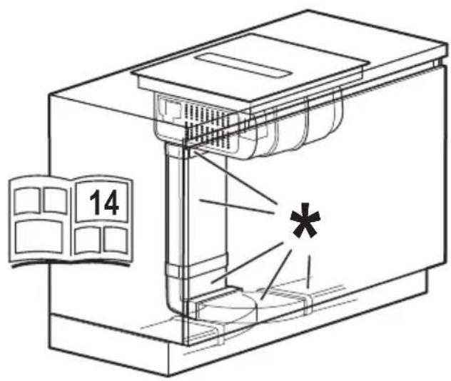
text_image
14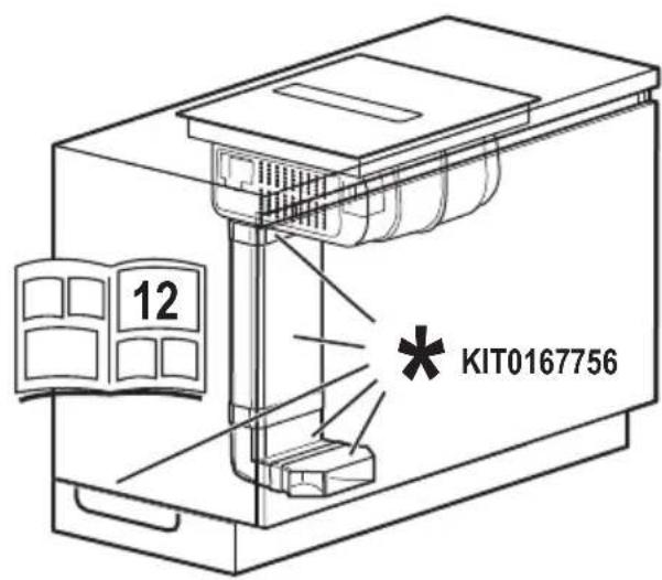
text_image
12 KIT0167756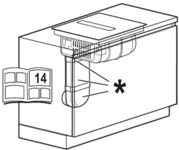
text_image
14 *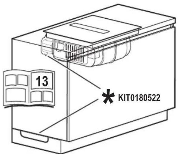
text_image
13 KIT0180522
text_image
Diagram showing a ruler and a triangular ruler with measurement markings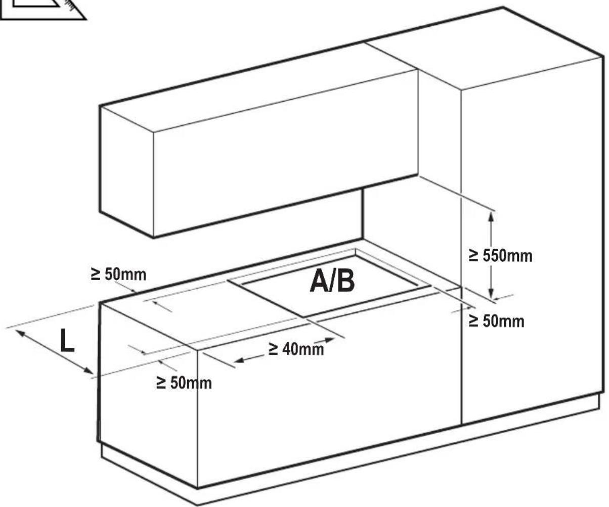
text_image
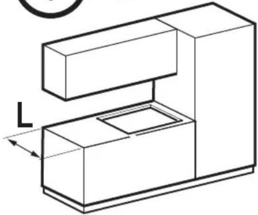
≥ 50mm A/B ≥ 50mm ≥ 40mm ≥ 50mm L ≥ 550mm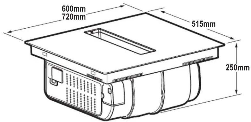
text_image
600mm 720mm 515mm 250mm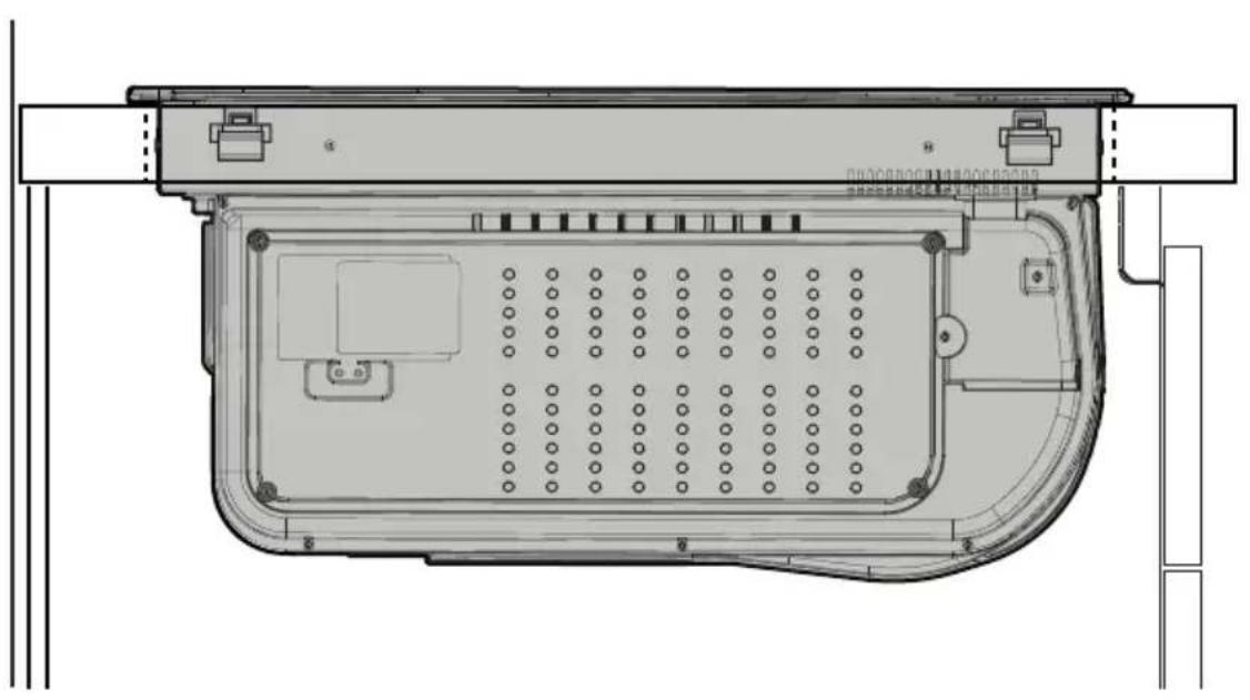
natural_image
Technical line drawing of a device rear panel with internal compartments and mounting points (no text or symbols)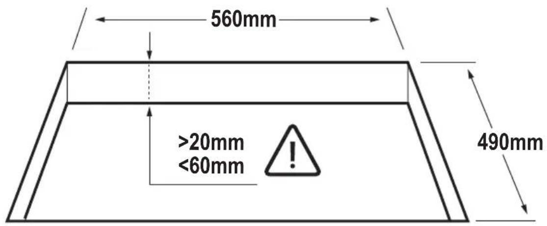
text_image
560mm >20mm <60mm 490mm
inst.B
text_image
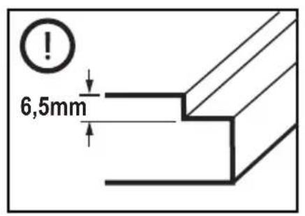
6,5mm
natural_image
Technical line drawing of a computer case with internal components and mounting brackets (no text or symbols)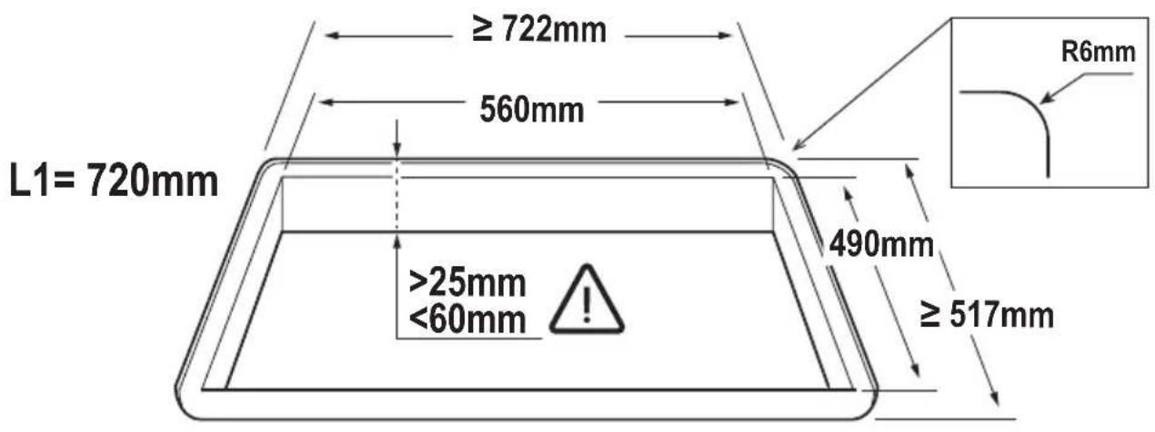
text_image
L1= 720mm ≥ 722mm 560mm 490mm ≥ 517mm R6mm >25mm <60mm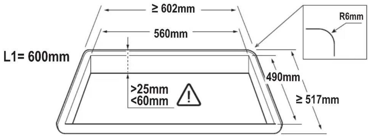
text_image
L1= 600mm ≥ 602mm 560mm 490mm ≥ 517mm R6mm >25mm <60mm3.1

text_image
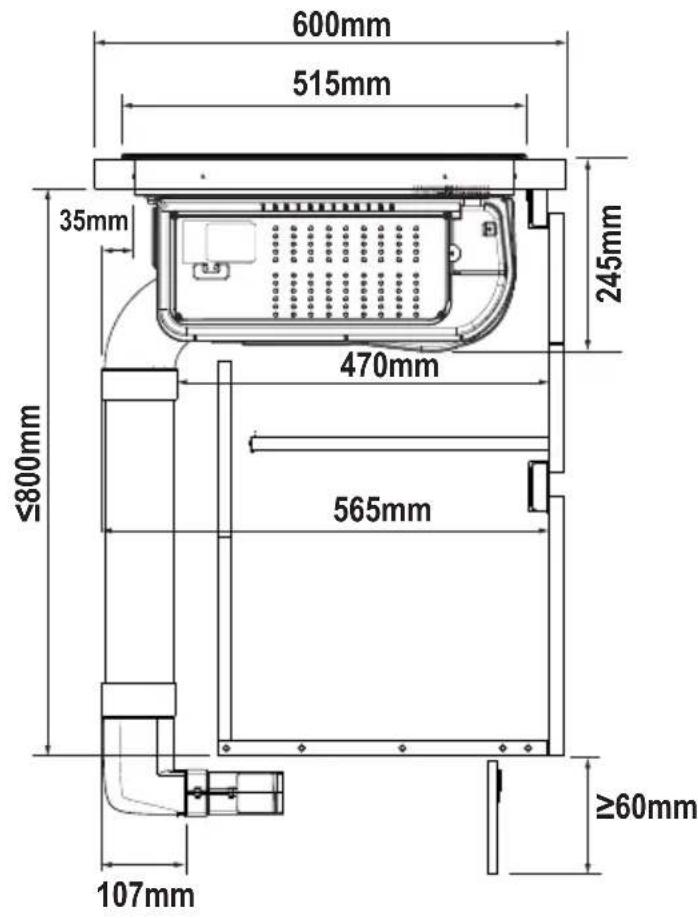
600mm 515mm 35mm 245mm ≤800mm 470mm 565mm ≥60mm 107mm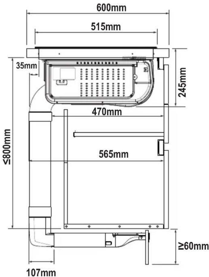
text_image
600mm 515mm 35mm 245mm 470mm ≤800mm 565mm ≥60mm 107mm
natural_image
Two simple geometric icons: a ruler and triangle, and a house with a circular arrow (no text or symbols)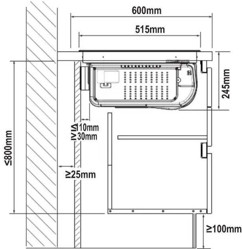
text_image
600mm 515mm ≤800mm 245mm VIA 110mm 30mm ≥25mm ≥100mm
natural_image
Two simple line drawings: a ruler and a house with an upward arrow (no text or symbols)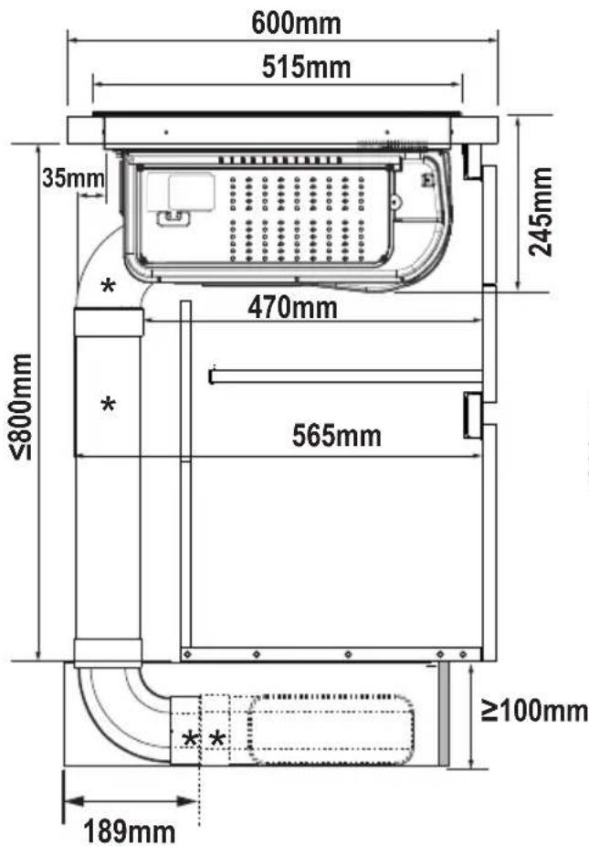
text_image
600mm 515mm 35mm 245mm 470mm ≤800mm 565mm ≥100mm 189mm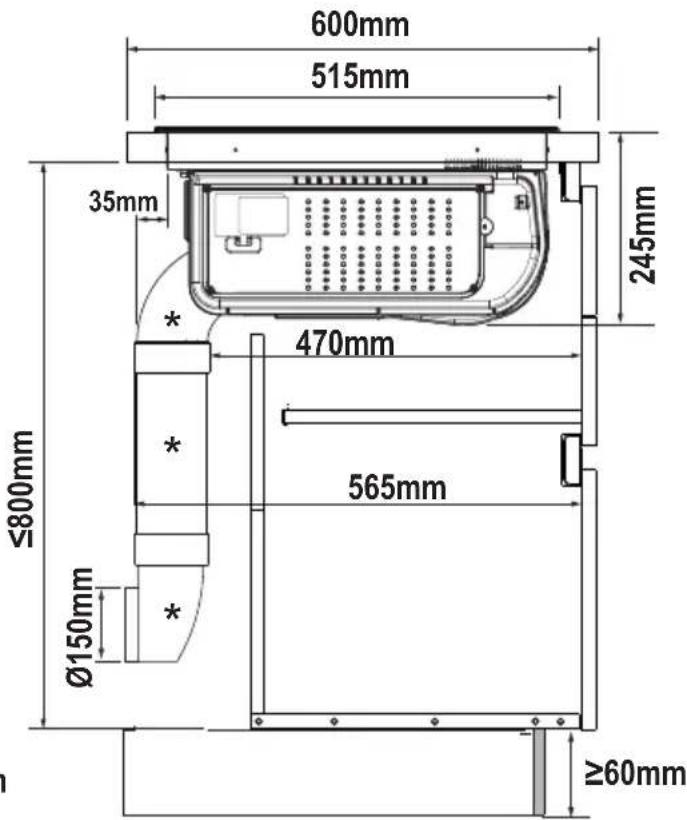
text_image
600mm 515mm 35mm 245mm 470mm 565mm Ø150mm Ø800mm ≥60mm
natural_image
Two simple line icons: a house with an upward arrow and a shopping cart (no text or symbols)KIT WINDOW

V-Hz
text_image
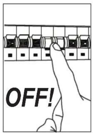
OFF!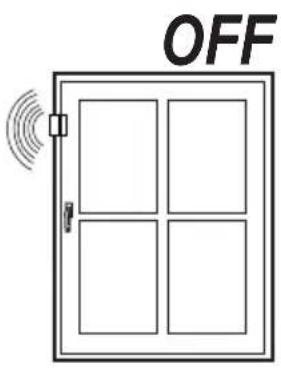
text_image
OFF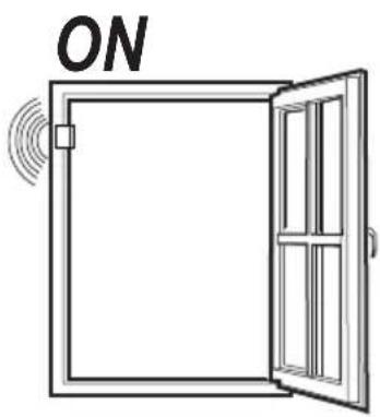
text_image
ON

text_image
KIT WINDOW 1 5A 2 3LN N L A B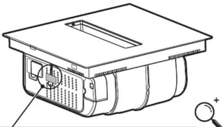
natural_image
Technical line drawing of an electronic device casing with internal components and a magnifying glass (no text or symbols)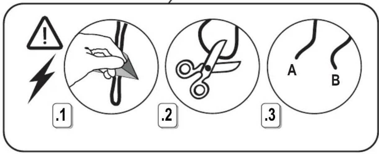
text_image
! 1 .2 .3 A B6
natural_image
Illustration of a computer monitor with a warning symbol (no text or labels on the device itself)

V-Hz
text_image
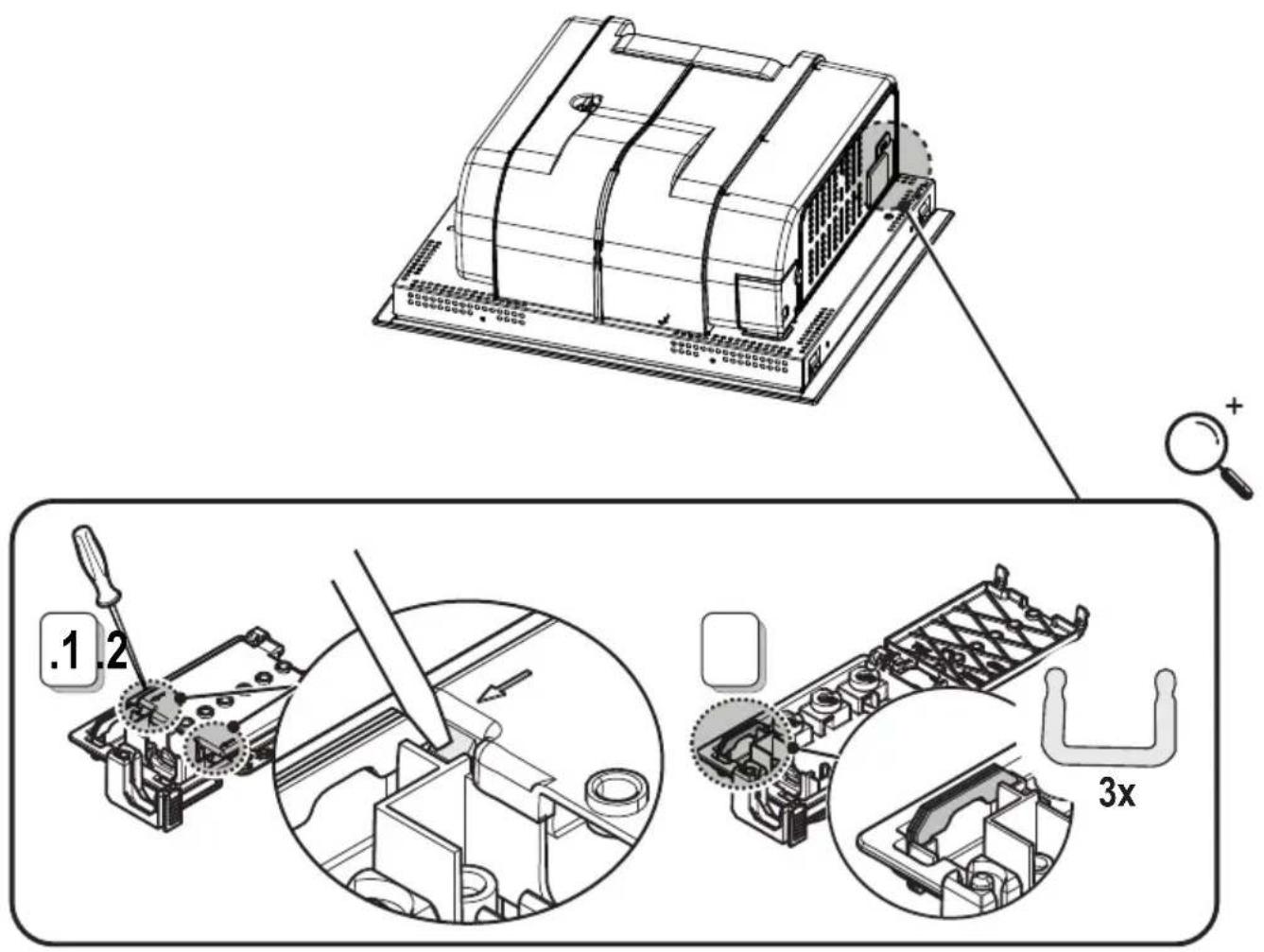
Technical diagram illustrating a mechanical assembly with labeled parts and magnified views, including tool path and 3x scaling.7


V-Hz
220V-240V \~ 50Hz/60Hz
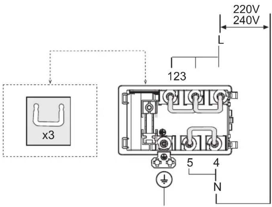
text_image
220V 240V L 123 x3 5 4 N380V-415V \~ 2N\~ 50Hz/60Hz
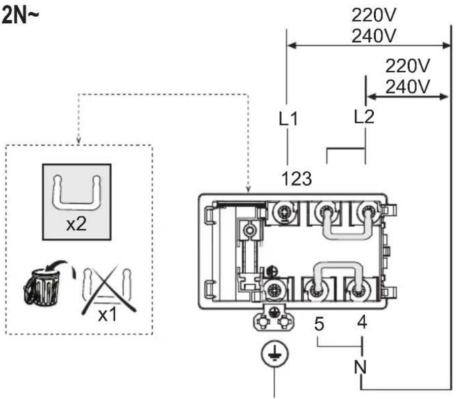
text_image
2N~ L1 L2 220V 240V 220V 240V x2 123 x1 5 4 N7.1
380V-415V \~ 3N\~ 50Hz/60Hz
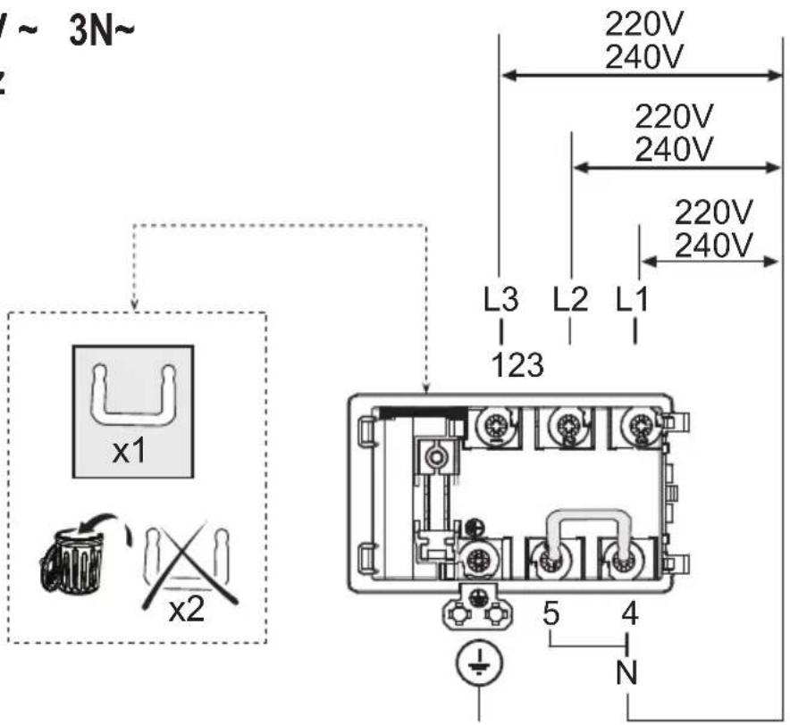
text_image
~ 3N~ L3 L2 L1 123 x1 x2 220V 240V 220V 240V 220V 240V 5 4 N220V-240V \~ 2N 2L 50Hz/60Hz
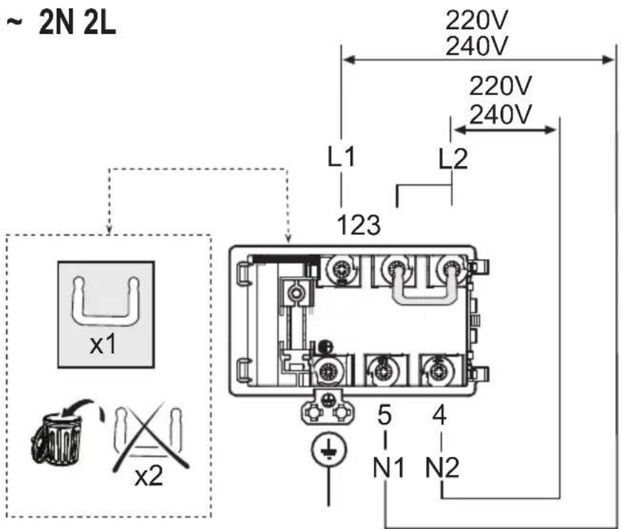
text_image
~ 2N 2L 220V 240V 220V 240V L1 L2 123 x1 x2 5 4 N1 N27.2


V-Hz
text_image
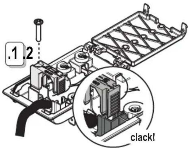
.1.2 clack!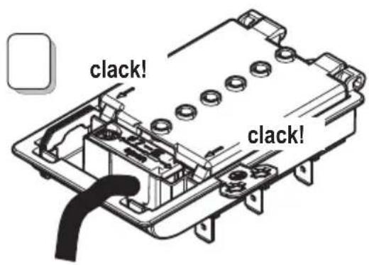
text_image
clack! clack!7.3
natural_image
Simple 3D icon of a mechanical component with no text or symbols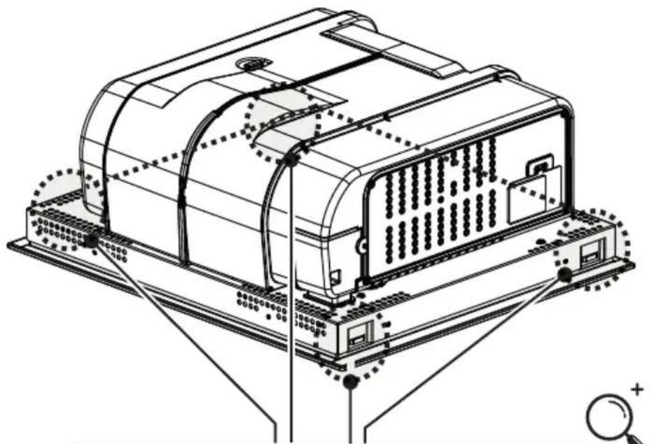
natural_image
Technical line drawing of a device chassis with mounting base and internal components (no text or symbols)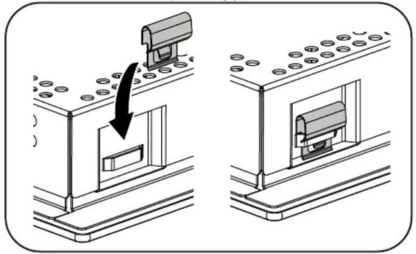
natural_image
Diagram showing two stages of a solar panel installation, with one being lifted by a black arrow and the other by a black arrow (no text or symbols present)inst.A
natural_image
Circular spiral pattern on a gray square background, no text or symbols present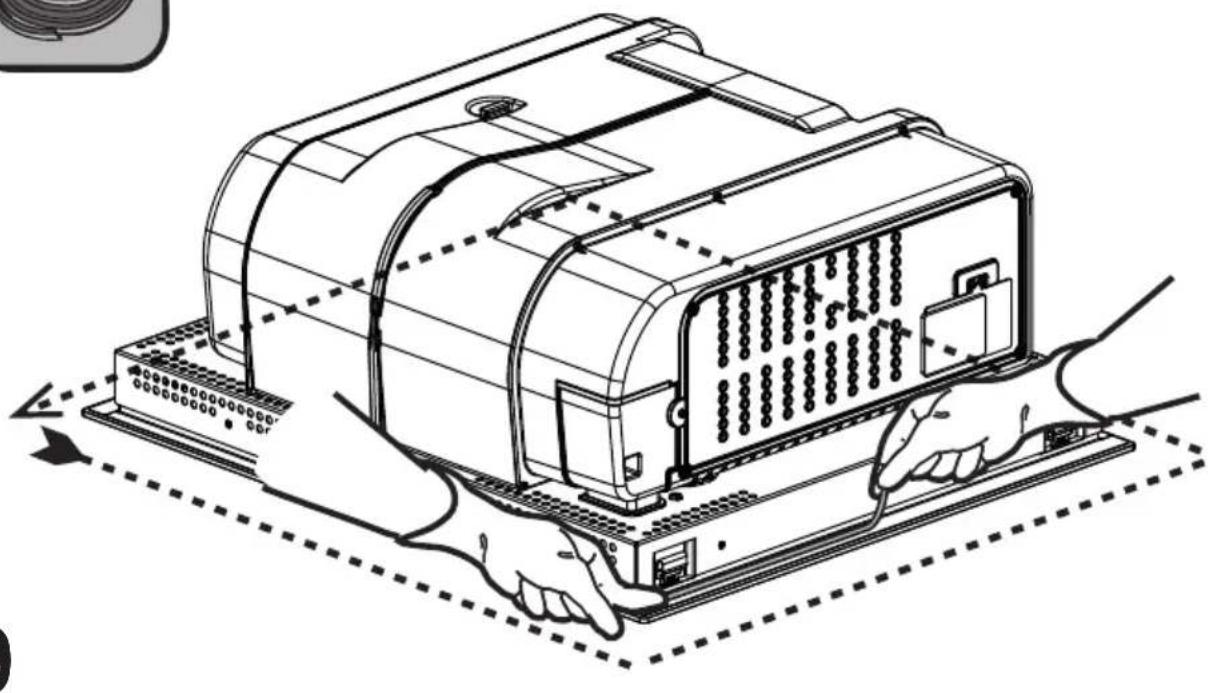
natural_image
Line drawing of a computer chassis with hands operating it, showing internal components and wiring (no text or symbols)9
inst.B
natural_image
Circular coil or spiral object with no visible text or symbols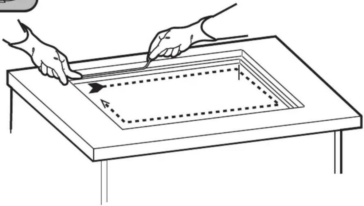
natural_image
Line drawing of two hands using a tool to cut a square frame on a table, with dashed lines indicating measurement or alignment (no text or symbols)10
inst.B
text_image
1x 10.110.2
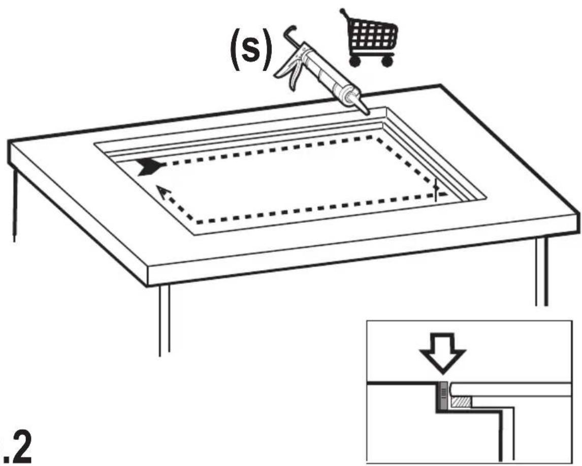
text_image
(s) .2KIT0167757
! L ≤ 650mm
natural_image
Technical line drawing of a mechanical assembly with no visible text or symbols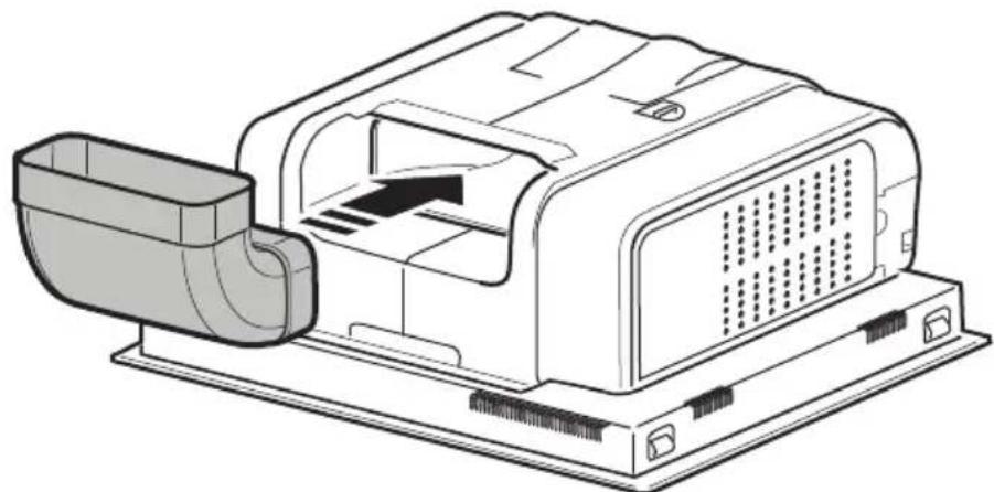
natural_image
Technical line drawing of a mechanical device with internal components and housing (no text or symbols)11
text_image
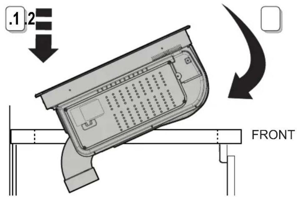
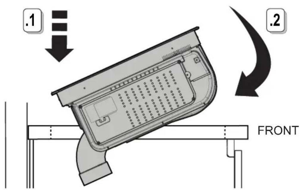
.1.2 FRONT11.1
KIT0167757

text_image
KIT0173527 .1 T1 *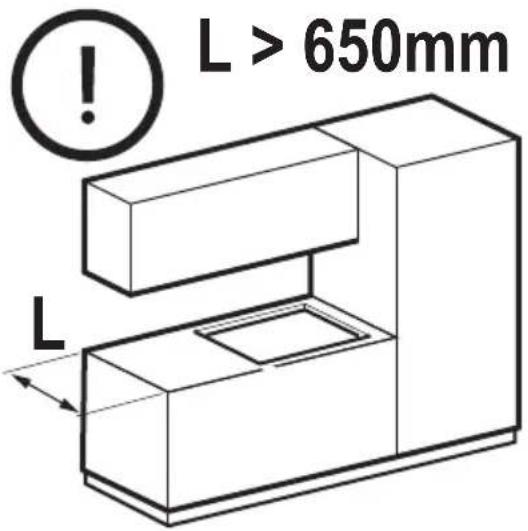
text_image
L > 650mm L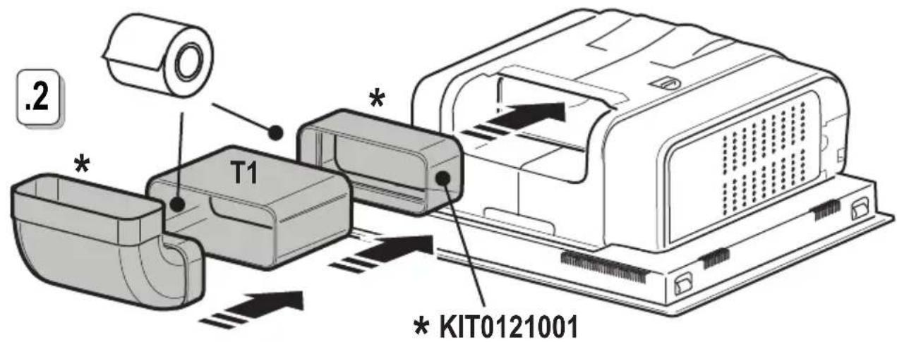
text_image
.2 T1 * * * KIT012100111.2
text_image
.1 .2 FRONT11.3
natural_image
Technical line drawing of a mechanical housing or enclosure component (no text or symbols)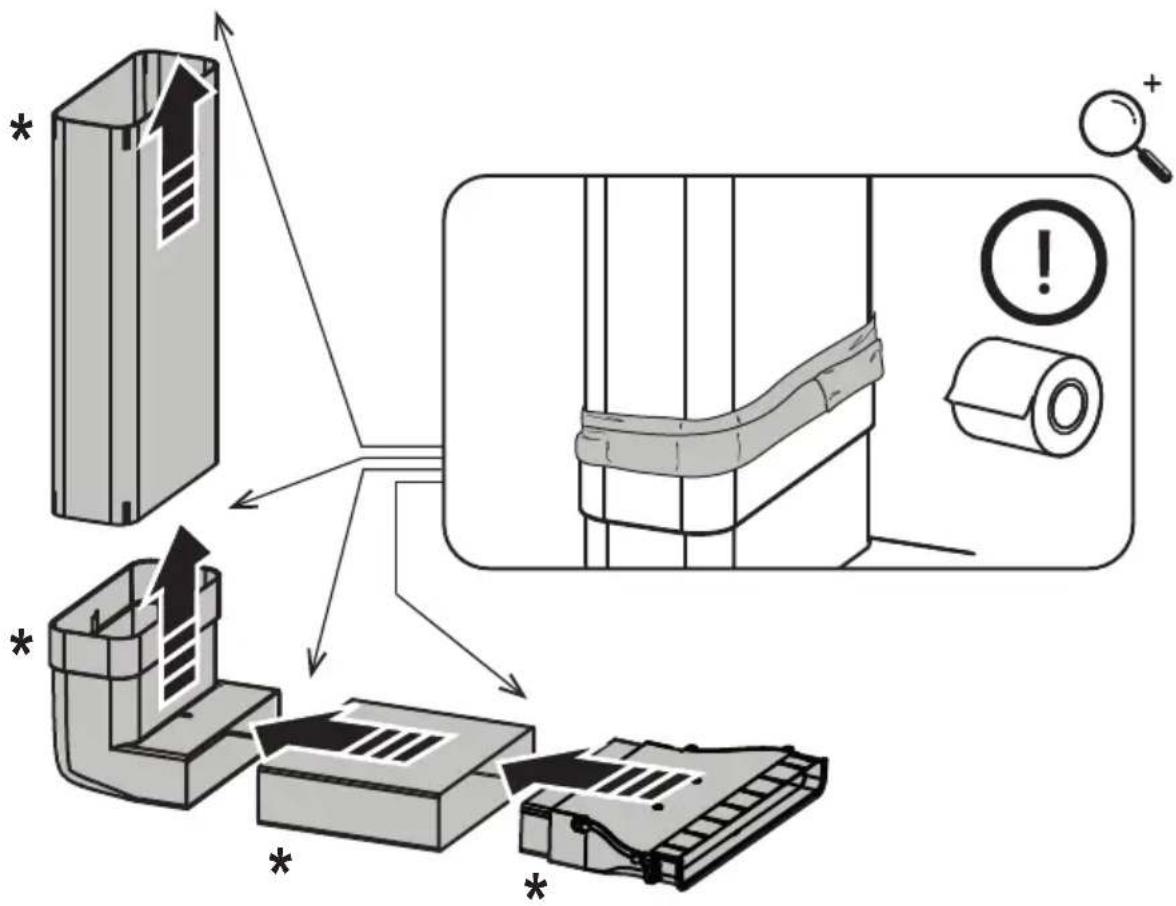
text_image
Diagram illustrating a mechanical assembly process with labeled components and warning indicators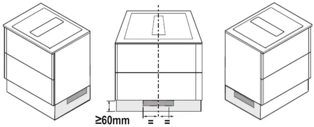
.1
natural_image
Two 3D mechanical parts with cutouts, shown from different angles (no text or symbols)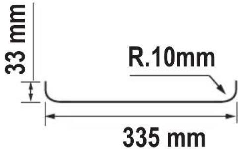
text_image
33 mm R.10mm 335 mm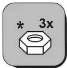
text_image
* 3x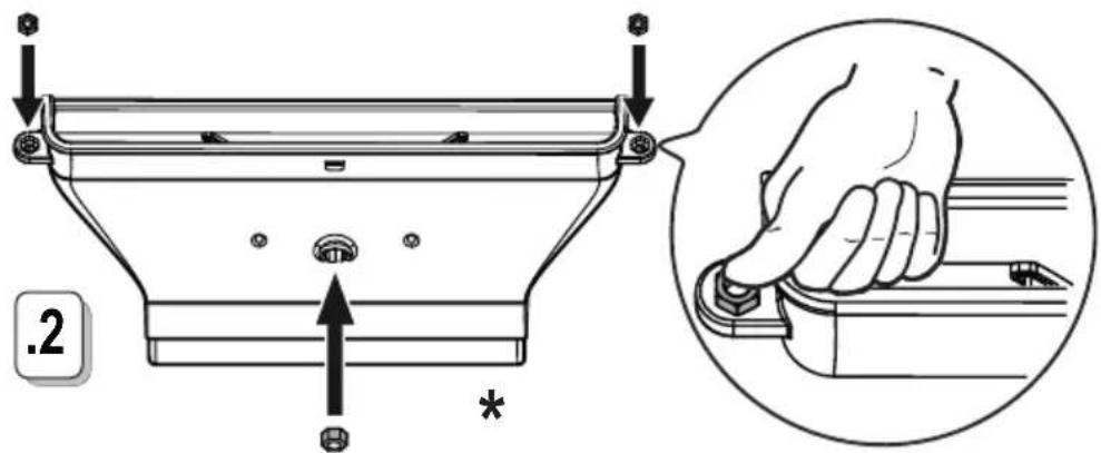
text_image
.2 *11.5
KIT0167757

www.elica.com
www.shop.elica.com
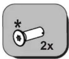
text_image
2x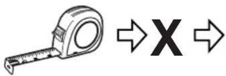
text_image
Diagram showing a tape measure and X symbol with directional arrows, likely indicating measurement or transformation.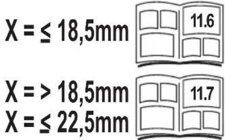
text_image
X = ≤ 18,5mm 11.6 X = > 18,5mm 11.7 X = ≤ 22,5mmX = ≤ 18,5mm
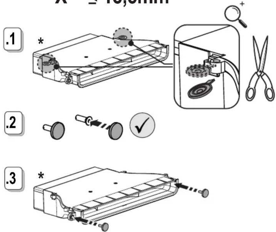
text_image
A = 10,6mm .1 * . 2 ✓ .3 *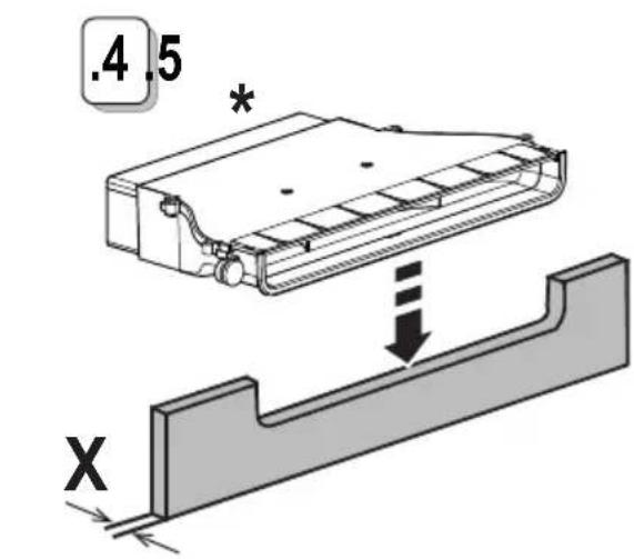
text_image
.4.5 * X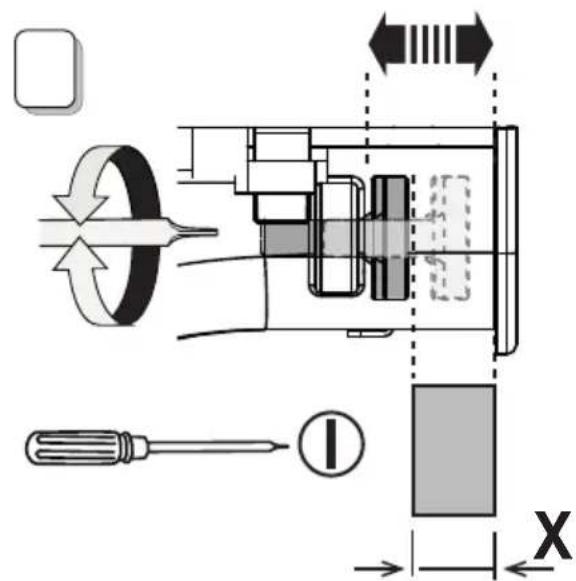
text_image
Technical diagram of a mechanical device with labeled components and directional arrows indicating motion or flow.11.6
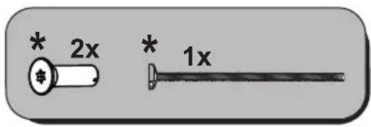
text_image
* 2x * 1xX ≥18,5mm ≤ 22,5mm
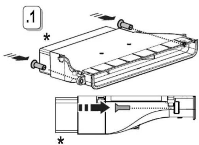
text_image
.1 *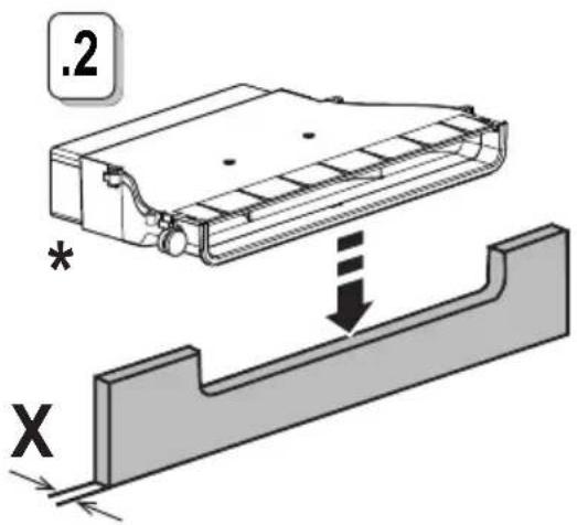
text_image
.2 * X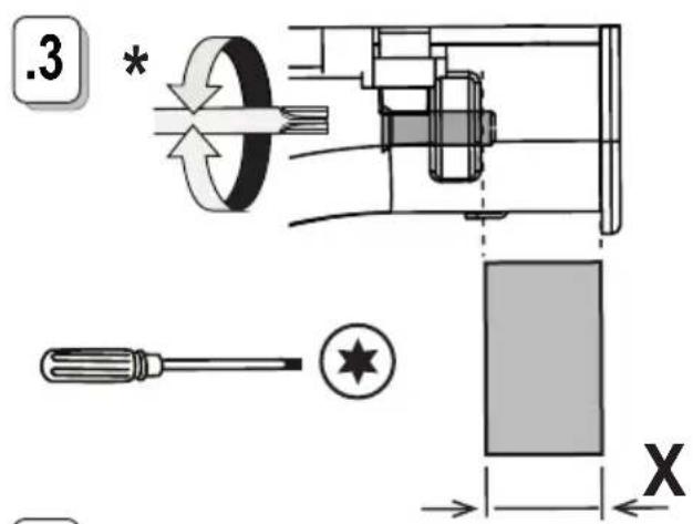
text_image
.3 * X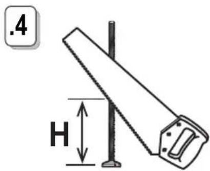
text_image
.4 H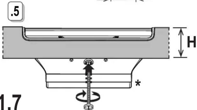
text_image
.5 H 1.7 *.6
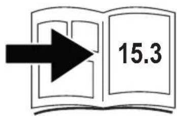
text_image
15.311.7
KIT0167756
* www.elica.com www.shop.elica.com
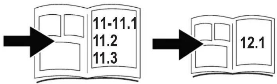
text_image
11-11.1 11.2 11.3 12.112
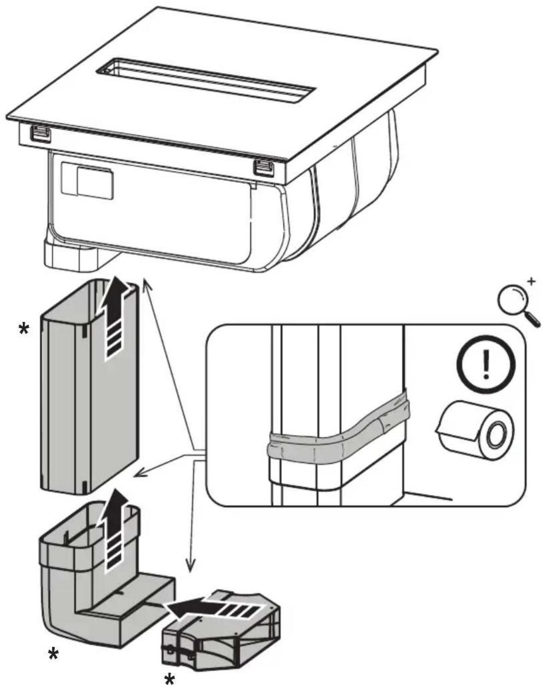
text_image
Technical diagram illustrating the installation and assembly of a air conditioner unit, with labeled components and warning indicators.12.1
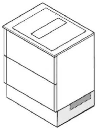
natural_image
Isometric line drawing of a rectangular box with a lid and base, no text or symbols present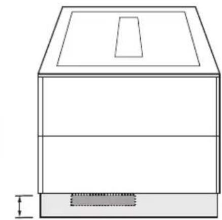
natural_image
Technical line drawing of a two-story cabinet or enclosure with a lid and base (no text or symbols)≥60mm
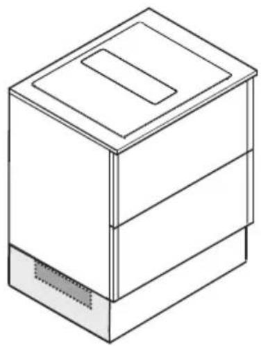
natural_image
Isometric line drawing of a three-tiered storage cabinet or rack unit (no text or symbols)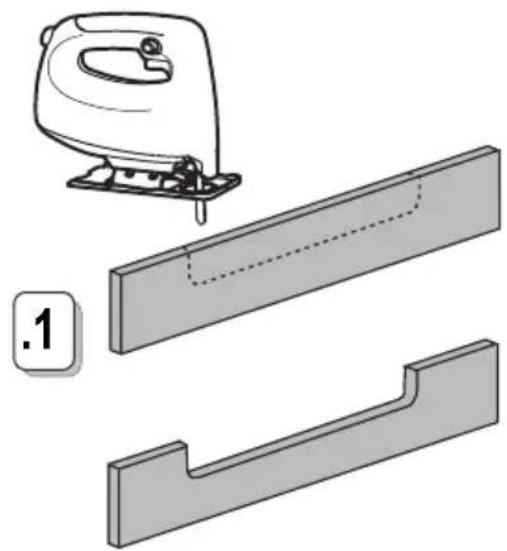
natural_image
Illustration of a sewing machine with a handle and two views of a wooden plank (no text or symbols)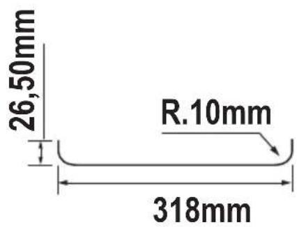
text_image
26,50mm R.10mm 318mm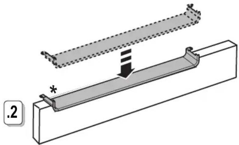
natural_image
Technical diagram of a mechanical assembly with a beam and support structure, showing no text or symbols.12.2
KIT0167756
* www.elica.com
www.shop.elica.com
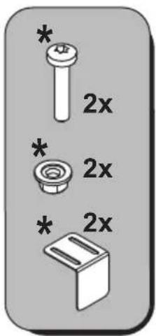
text_image
* 2x * 2x * 2x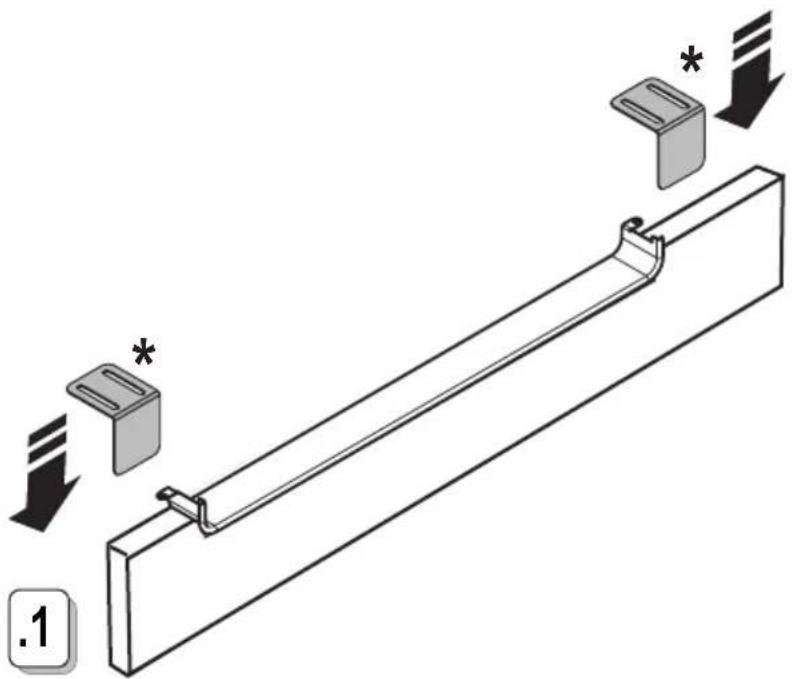
natural_image
Technical illustration of a mechanical component with directional arrows and a label '1' (no text or symbols on the diagram itself)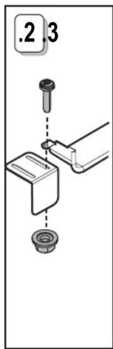
text_image
.2.3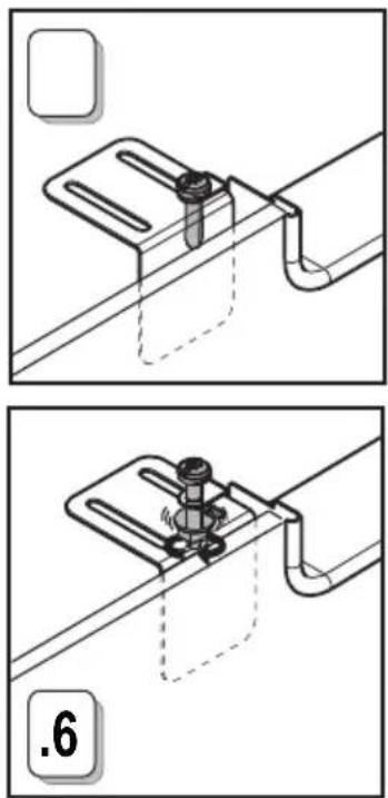
natural_image
Technical line drawing showing two mechanical assembly steps with no visible text or symbols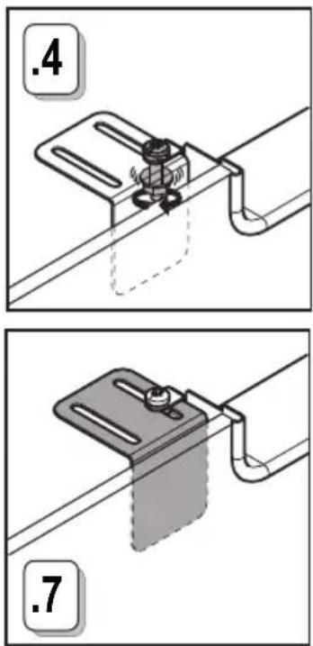
text_image
.4 .7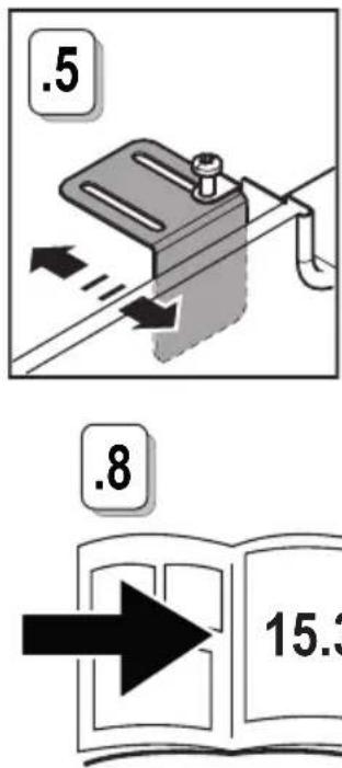
text_image
.5 .8 15.312.3
text_image
.8 15.3KIT0180522

* www.elica.com
www.shop.elica.com
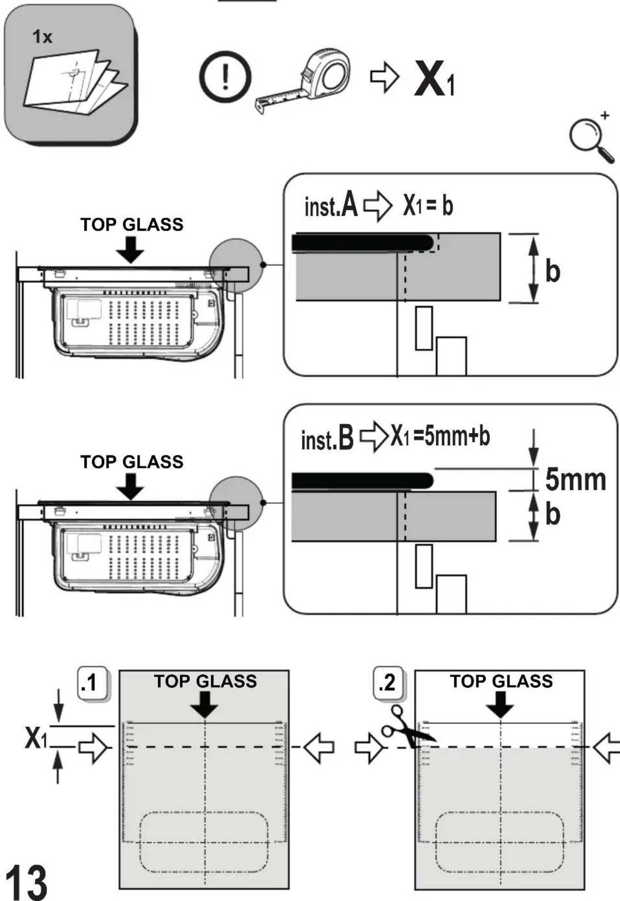
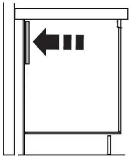
natural_image
Simple line drawing of a door frame with a left arrow and three squares inside (no text or symbols)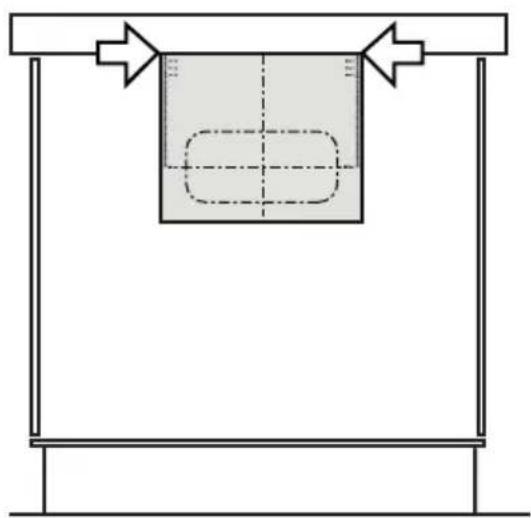
natural_image
Simple line drawing of a container with arrows indicating direction, no text or symbols present13.1
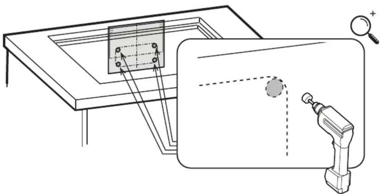
natural_image
Diagram showing a table setup with a magnifying glass and a mechanical tool, no text or symbols present.13.2
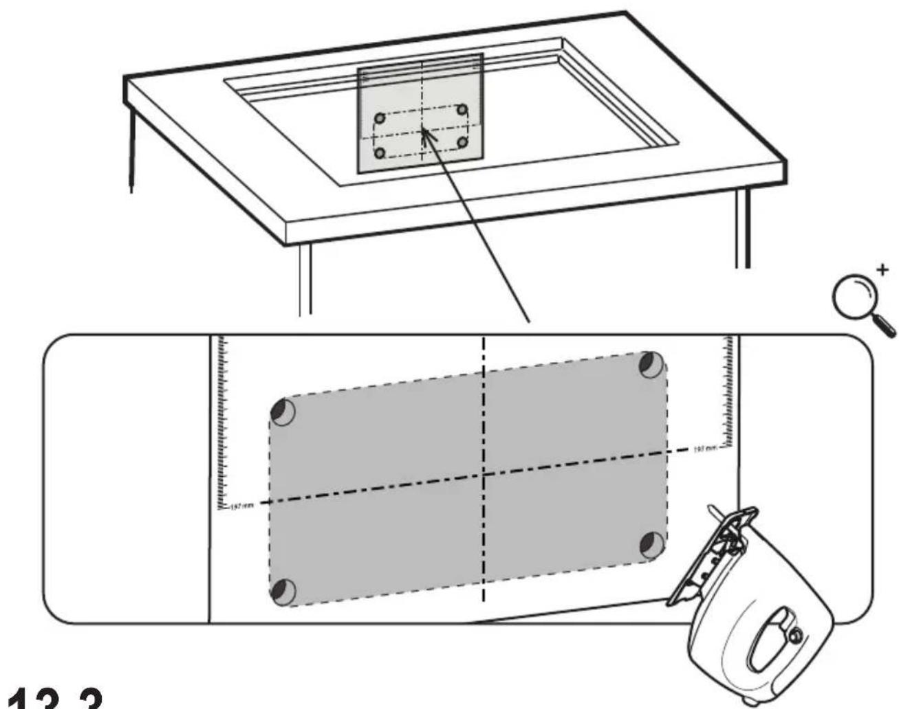
text_image
12.213.3
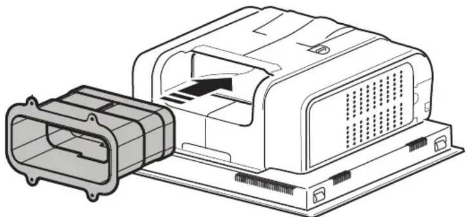
natural_image
Technical line drawing of an electronic device housing with a connector housing and internal components (no text or symbols)13.4
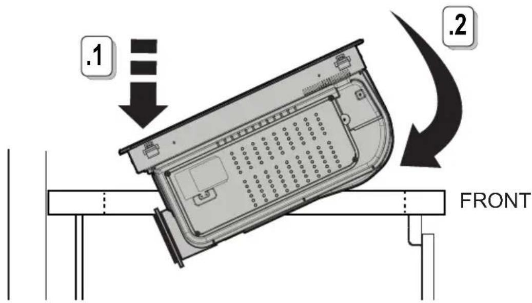
text_image
.1 .2 FRONT13.5
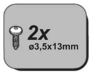
text_image
2x ø3,5x13mm
text_image
13.6 .1 .2 2x Ø3,5x13mm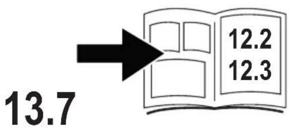
text_image
13.7 12.2 12.3
* www.elica.com www.shop.elica.com
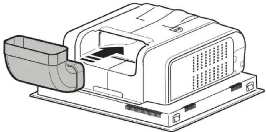
natural_image
Technical line drawing of a mechanical device with a housing and internal components (no text or symbols)14
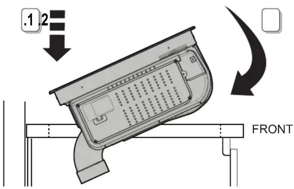
text_image
.1.2 FRONT14.1
* www.elica.com www.shop.elica.com

natural_image
Technical line drawing of a mechanical housing or enclosure component (no text or symbols)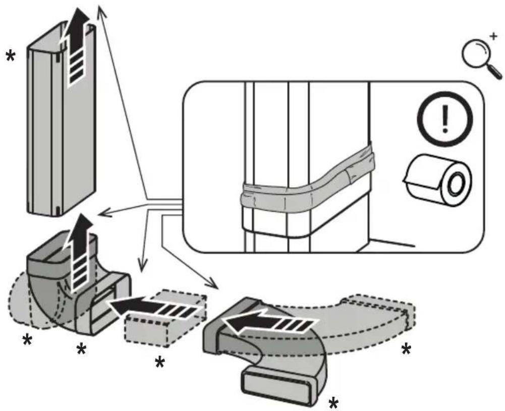
text_image
Diagram illustrating a mechanical assembly process with labeled components and warning indicators14.2
text_image
15.314.3

natural_image
Simple 3D illustration of a rectangular box with a side panel, labeled '2x' (no other text or symbols)
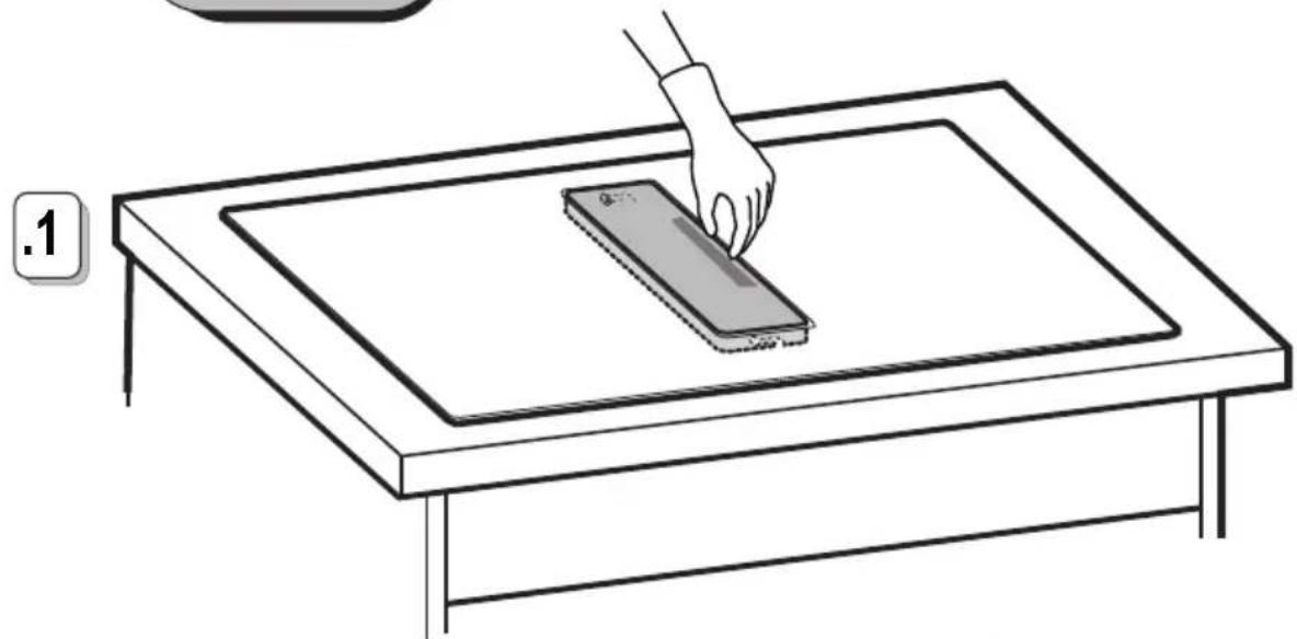
natural_image
Line drawing of a hand pressing down on a rectangular object on a table (no text or symbols)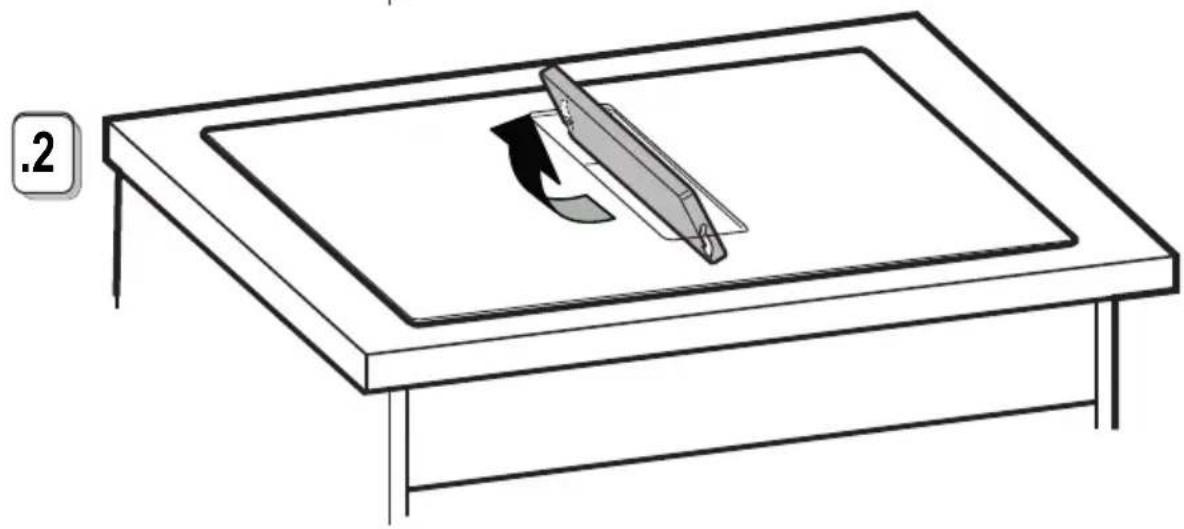
natural_image
Line drawing of a table with a pen and paper clip, no text or symbols present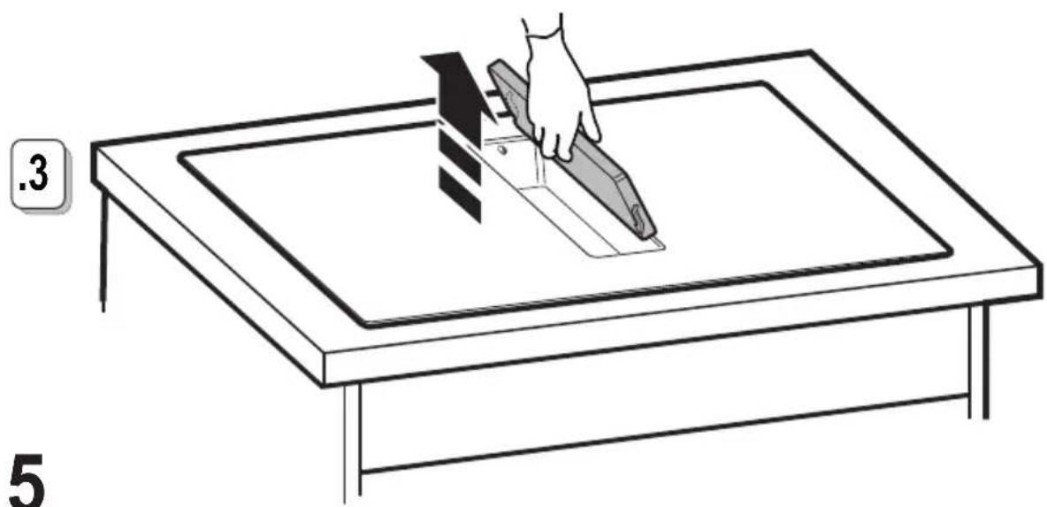
natural_image
Line drawing of a hand using a tool to cut or mark a rectangular object on a table (no text or symbols)

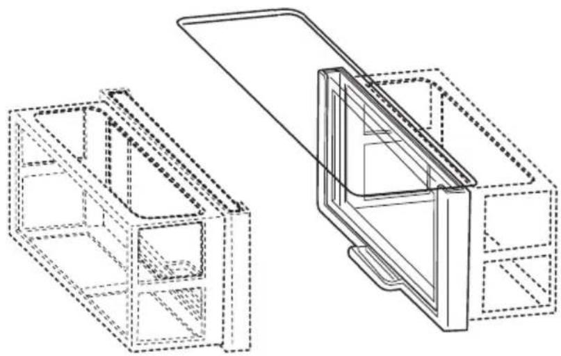
natural_image
Technical line drawing of two 3D architectural or mechanical components with dashed outlines, no text or symbols present.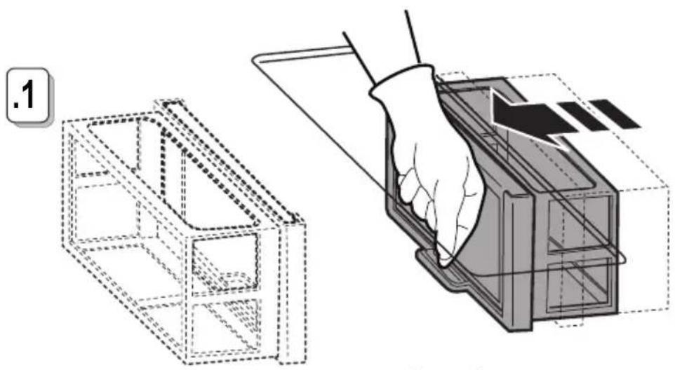
natural_image
Technical illustration showing a 3D model of a rectangular box being cut with a hand using a tool to insert or install a component (no text or symbols present)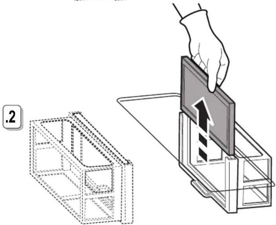
natural_image
Illustration showing a hand placing a 3D panel into a transparent case, with a smaller 2D box nearby (no text or symbols)15.1
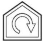

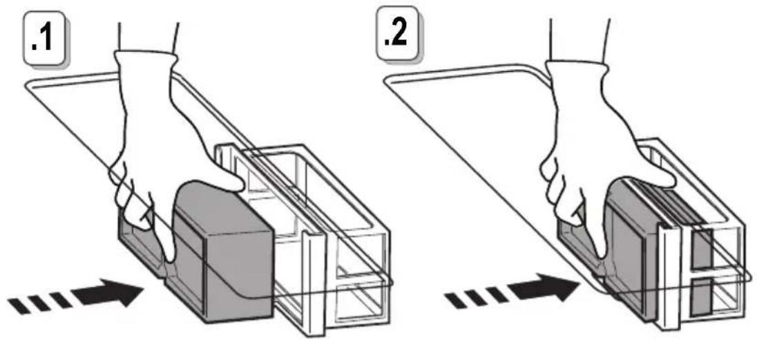
text_image
.1 .2
text_image
Diagram illustrating two steps of a device assembly or packaging process, labeled 3 and 4, with hand gestures indicating step 3 and step 4.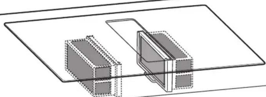
natural_image
Technical line drawing of two rectangular components with dashed outlines, no text or symbols present15.2

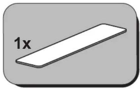
text_image
1x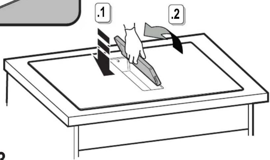
text_image
.1 .215.3
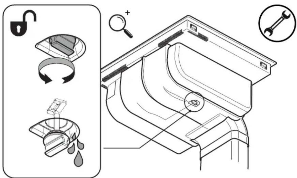
text_image
Technical diagram illustrating the installation of a washing machine with labeled components and instructions16
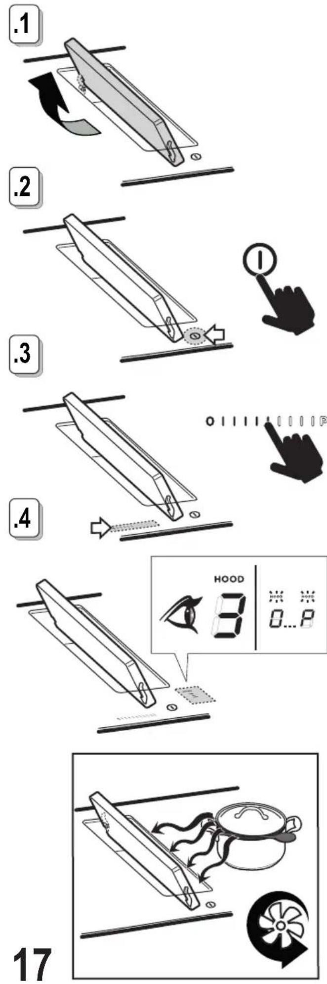
.1
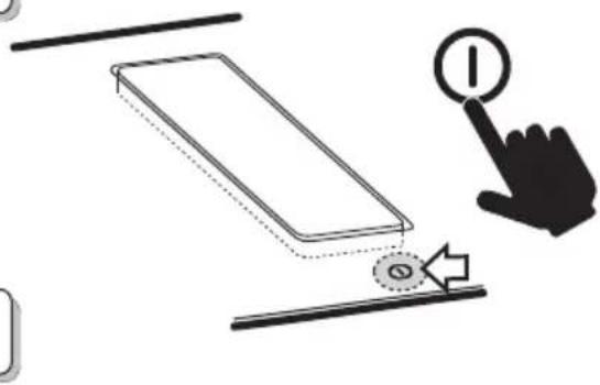
text_image
Diagram showing a hand pressing a button on a device with an icon and directional arrow, likely illustrating a process or control mechanism..2
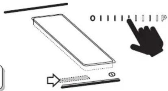
natural_image
Diagram showing a hand cursor clicking a button onto a rectangular device, with arrows indicating movement (no text or symbols).3
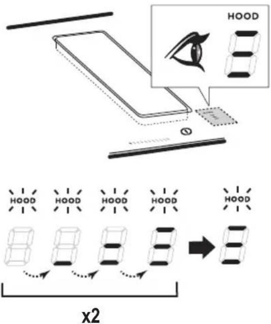
text_image
HOOD x2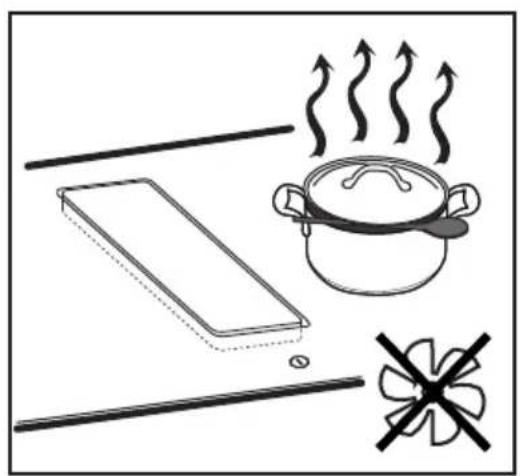
natural_image
Simple line drawing of a cooking scene with a pan, steaming pot, and a fan (no text or symbols)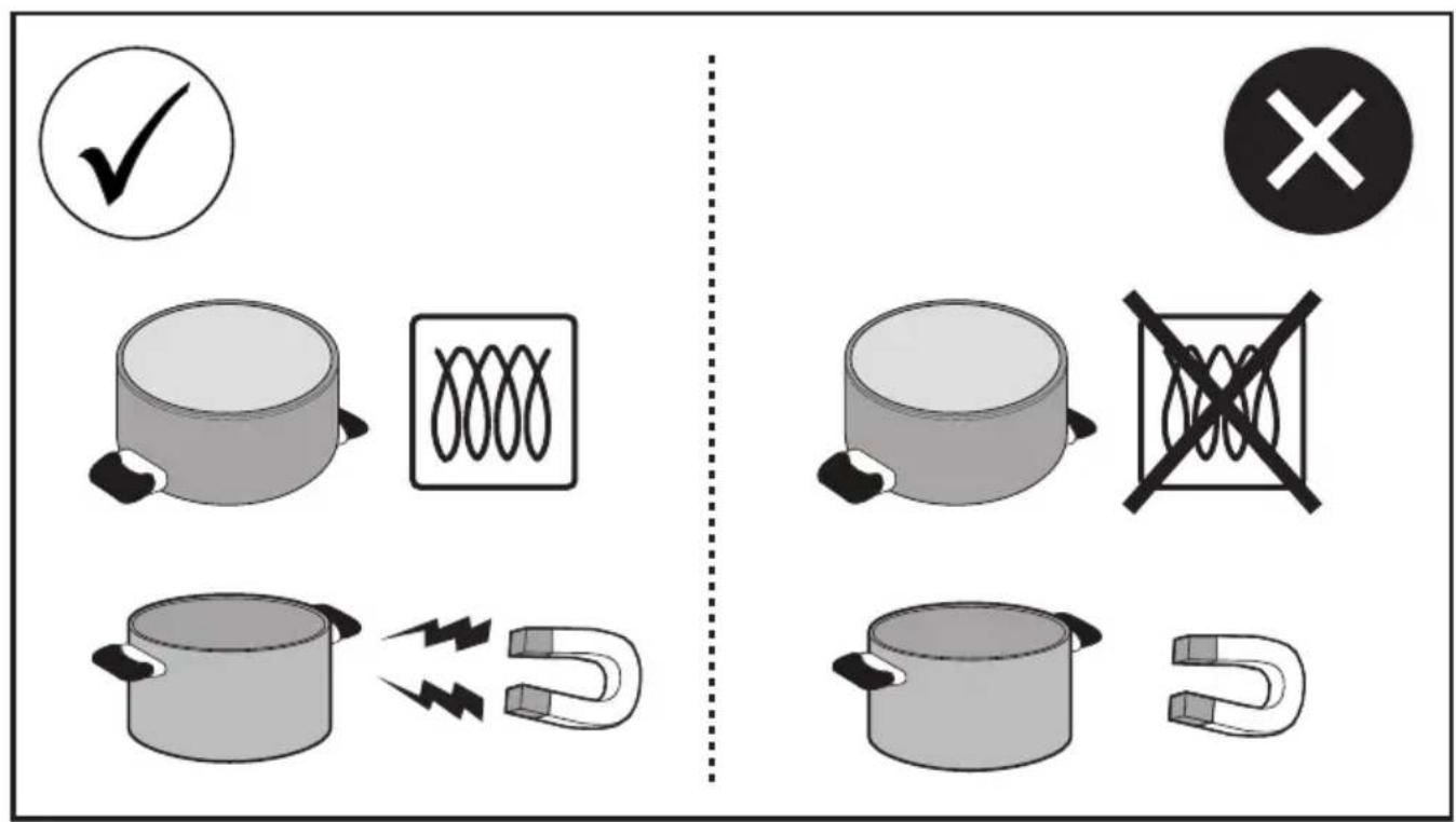
text_image
Diagram illustrating electrical hazard symbols for cooking pots, solenoid, and magnet, with checkmark and cross symbols indicating compliance or failure.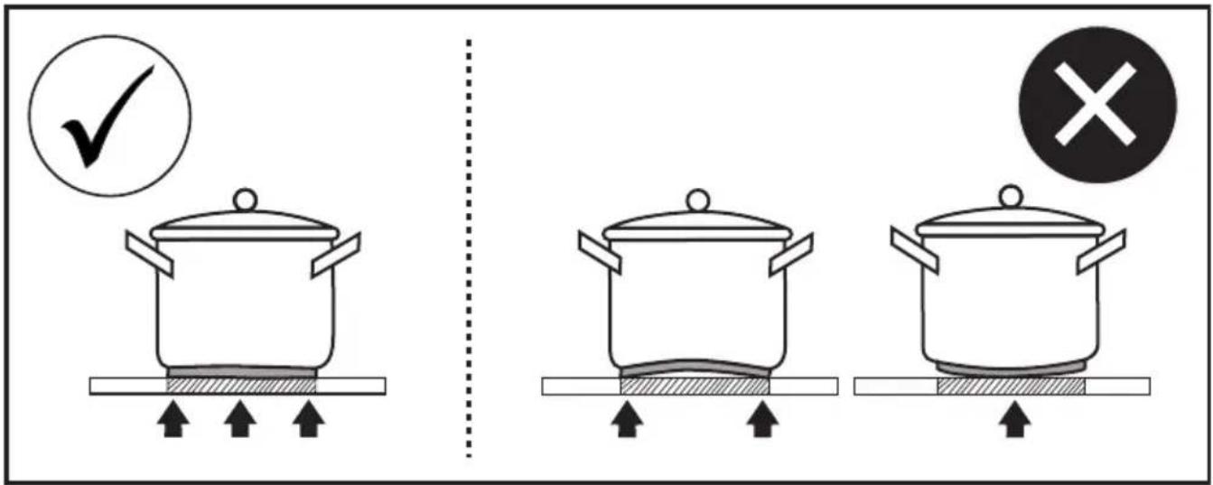
text_image
Diagram illustrating cooking process with three pots, a checkmark, and a cross symbol indicating removal or rejection.