IR 120150D - Thermometer VOLTCRAFT - Free user manual and instructions
Find the device manual for free IR 120150D VOLTCRAFT in PDF.
| Brand | Voltcraft |
| Model | IR 120150D |
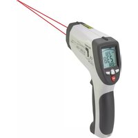
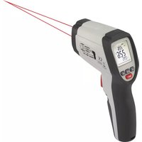
| Product type | Infrared thermometer with contact probe |
| Dimensions | 204 x 52 x 155 mm |
| Weight | 330 g |
| Power supply | 9 V battery (block) |
| IR measuring range | -50 to +1200 °C |
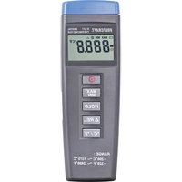
| Contact measuring range (type K) | -50 to +1370 °C |
| Resolution | 0,1 °C/°F |
| IR optics | 50:1 |
| Aiming laser | Dual laser, class 2, < 1 mW, 630-670 nm |
| Adjustable emissivity | 0,10 to 1,00 |
| Memory | 30 readings |
| Interface | USB for data transfer |
| Display | Dot matrix graphic, backlit |
| Functions | Min, Max, Average, Difference, High/low alarm, Data Hold, continuous measurement |
| Auto power off | 7 to 60 seconds adjustable |
| Operating temperature | 0 to +50 °C |
| Storage temperature | -10 to +60 °C |
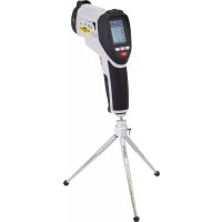
| Delivery contents | Thermometer, battery, type K probe, tripod, USB cable, software CD, carrying case, instruction manual |
| Cleaning | Lens: compressed air, lens brush; housing: soft lint-free cloth |
| Safety | Do not look into the laser, avoid reflective surfaces, do not measure through glass |
Frequently Asked Questions - IR 120150D VOLTCRAFT
User questions about IR 120150D VOLTCRAFT
0 question about this device. Answer the ones you know or ask your own.
Ask a new question about this device
Download the instructions for your Thermometer in PDF format for free! Find your manual IR 120150D - VOLTCRAFT and take your electronic device back in hand. On this page are published all the documents necessary for the use of your device. IR 120150D by VOLTCRAFT.
USER MANUAL IR 120150D VOLTCRAFT
GB Operating Instructions
IR 1201-50D USB IR thermometer
Item No. 1599564 Page 27 - 50
© Notice d'emploi
www.business.conrad.at
text_image
Diagram of a medical imaging device with numbered parts for identificationtext_image
E F SCAN HOLD 15:00 ε=0.95 Max 30.6 22.3 °C Min 15.1 A J MnMx Save Avgnatural_image
Two circular diagrams with internal dotted lines and asterisk symbols, no text or labels present.9. Inbetriebnahme
text_image
SCAN 18:12 ε=0.95 Max 24.2 22.8 °C TK 32.0 MnMx Save Avgc) Zusatzfunktionen
text_image
HOLD 15:24 ε=0.95 Max 38.4 23.1 °C Min 20.4 MnMx Save Avg
text_image
HOLD 15:24 ε=0.95 Avg 26.2 23.1 °C Dif 18.0 MnMx Save Avgtext_image
HOLD 15:24 ε=0.95 Max 31.2 28.2 °C Min 22.0 MnMx Save Avg HOLD 15:24 ε=0.95 Max 31.2 28.2 °C Min 22.0 Yes Esc HOLD 15:24 ε=0.95 Saving 06/30 28.2 °C 15:24 05/10/2013 Yes Esctext_image
HOLD 15:28 ε=0.95 Max 31.2 28.2 °C Min 22.0 Unit Mem E → HOLD 15:28 ε=0.95 Memory 02/26 28.2 °C 09:34 24/09/2013 Del ▲Daten löschen
text_image
HOLD ▲ 15:30 ■■■ ε=0.95 Max 31.2 28.2 °C Min 22.0 Unit Mem E → HOLD ▲ 15:30 ■■■ ε=0.95 ▼ Tab ▲text_image
HOLD 15:30 ε=0.95 Max 31.2 28.2 °C Min 22.0 Unit Mem E HOLD 15:30 ε=0.95 Tab HOLD 15:30 ε=0.95 Default Ox Aluminum Ox Brass Ox Copper Paint OKtext_image
HOLD 15:35 ε=0.95 Max 31.2 28.2 °C Min 22.0 Hi Set Lo HOLD 15:35 ε=0.95 Hi Alarm 300.0 °C Off ▲ HOLD 15:35 ε=0.95 Hi Hi Alarm 300.0 °C On ▲ HOLD 15:38 ε=0.95 Max 31.2 28.2 °C Min 22.0 Hi Set Lo HOLD 15:38 ε=0.95 Lo Alarm 10.0 °C Off ▲ HOLD 15:38 ε=0.95 Hi Lo Lo Alarm 10.0 °C On ▲- Introduction......28
- Explanation of symbols....28
- Intended use....29
- Package contents 29
- Features and functions ...... 30
- Safety information....30
a) General information....30
b) Laser....31
c) Battery 32
- Product overview 33
a) IR thermometer....33
b) Display....34
- Product description 34
a) Function....34
b) IR measuring optics - ratio measuring distance:measuring surface....35
c) Target laser....35
- Operation 36
a) System settings 36
b) Setting the time....37
c) Setting the date ....37
d) Setting the display backlight....37
e) Setting the signal beep....37
f) Setting the display contrast 37
g) Setting the automatic power-off time 38
h) Setting interface data transmission 38
- Taking measurements....38
a) IR measurement....39
b) Contact measurement 39
c) Additional functions 40
- Care and cleaning....47
a) General information....47
b) Cleaning the lens....47
c) Cleaning the housing....47
d) Inserting/changing the battery 47
-
Troubleshooting....48
-
Disposal 48
a) Product 48
b) Batteries 48
- Technical data....49
1. Introduction
Dear customer,
Thank you for purchasing this product.
This product complies with statutory national and European regulations.
To ensure that the product remains in this state and to guarantee safe operation, always follow the instructions in this manual.

These operating instructions are part of this product. They contain important information on setting up and using the product. Do not give this product to a third party without the operating instructions. Therefore, retain these operating instructions for reference!
For technical queries, please contact:
International: www.conrad.com/contact
United Kingdom: www.conrad-electronic.co.uk/contact
2. Explanation of symbols

The symbol with an exclamation mark in a triangle is used to highlight important information in these operating instructions. Always read this information carefully.

The arrow symbol alerts the user to the presence of important tips and notes on using the device.
3. Intended use
The infrared thermometer allows contactless measurement of surface temperatures. It measures the temperature by means of the infrared energy emitted by each object. Due to the contactless measurement, the product is ideal for dangerous objects, objects that are difficult to access, moving objects or objects supplied with electrical voltage. It cannot measure through transparent surfaces such as glass, plastics, water, etc. The temperature measurement range is -50 to +1200 °C. A dual laser targeting device facilitates specification of the measurement range.
In addition, contact measurement with a K-type thermocouple sensor in the measuring range from -50 to +1370 °C, depending on the sensors, is possible.
The IR thermometer itself must not come into contact with the measured temperature. Always maintain sufficient safety distance and observe the permitted ambient conditions.
Diagnostic application for medical purposes is not permissible.
The emission level can be adjusted to the surface properties of the measured object at hand.
The IR thermometer also has an internal memory for up to 30 measured values. These values can be read on the display of the measuring device or via the built-in USB port.
A 9 V block battery is required for the voltage supply. Do not use any other power supply.
For safety and approval purposes, you must not rebuild and/or modify this product. Using the product for purposes other than those described above may damage the components. In addition, improper use can cause injuries. Read the instructions carefully and store them in a safe place. Only make this product available to third parties together with its operating instructions.
All company and product names are trademarks of their respective owners. All rights reserved.
4. Package contents
- IR thermometer
- Battery
- Type-K temperature sensor (measurement range -20 to +250 °C)
- Tripod
- USB cable
- Software CD
- Transport case
- Operating instructions
Up-to-date operating instructions
To download the latest operating instructions, visit www.conrad.com/downloads or scan the QR code on this page. Follow the instructions on the website.

5. Features and functions
- 50:1 optics
• IR measurement range -50 to +1200 °C - Graphic dot matrix display
- USB interface
- Dual-laser for exact marking of the measurement spot
- Data hold
• Permanent measuring function - Min/Max/∅ and difference display
- Hi/Lo alarm
- Adjustable emission level
• K-type-sensor measuring function - Backlit display
• 30 measured-values memory
6. Safety information

Read the operating instructions and safety information carefully. If you do not follow the safety information and information on proper handling in these operating instruction, we will assume no liability for any resulting personal injury or damage to property. Such cases will invalidate the warranty/guarantee.
a) General information
- The device is not a toy. Keep it out of the reach of children and pets.
- Do not leave packaging material lying around carelessly. It may become a dangerous toy for children.
- Protect the product from extreme temperatures, direct sunlight, strong jolts, high humidity, moisture, flammable gases, vapours and solvents.
- Do not place the product under any mechanical stress.
- If it is no longer possible to operate the product safely, stop using it and prevent unauthorised use. Safe operation can no longer be guaranteed if the product:
- is visibly damaged,
- is no longer working properly,
- has been stored for extended periods in poor ambient conditions or
-
has been subjected to any serious transport-related stress.
-
Always handle the product carefully. Jolts, impacts or a fall even from a low height may damage the product.
- Always observe the safety and operating instructions of any other devices which are connected to the product.
- Do not use in the immediate proximity of strong magnetic or electromagnetic fields or transmission aerials. These may distort the measurements.
- Water vapour, dust, smoke and/or vapours may impair the optical characteristics and lead to faulty measurements!
- Always comply with the accident prevention regulations for electrical equipment when using the product in commercial facilities.
- In schools, educational facilities, hobby and DIY workshops, measuring devices must be operated under the responsible supervision of qualified personnel.
- Never switch the device on immediately after taking it from the cold into a warm environment. The condensation generated may destroy the product. First allow the product to reach room temperature before switching it on.
- Consult a technician if you are not sure how to use or connect the product.
- Maintenance, modifications and repairs must be done by a technician or a specialist repair centre.
- If you have questions which remain unanswered by these operating instructions, contact our technical support service or other technical personnel.
b) Laser
- When operating the laser equipment, always make sure that the laser beam is directed so that no one is in the projection area and that unintentionally reflected beams (e.g. from reflective objects) cannot be directed into areas where people are present.
- Laser radiation can be dangerous, if the laser beam or its reflection enters unprotected eyes. Before using the thermometer, familiarise yourself with the statutory regulations and instructions for operating such a laser device.
- Never look into the laser beam and never point it at people or animals. Laser radiation can seriously damage your eyes.
- If laser radiation enters your eyes, close your eyes immediately and move your head away from the beam.

- If your eyes have been irritated by laser radiation, do not continue to carry out tasks with safety implications, such as working with machines, working from great heights or close to high voltage. Do not drive any vehicles until the irritation has completely subsided.
- Do not point the laser beam at mirrors or other reflective surfaces. The uncontrolled, reflected beam may strike people or animals.
- Never open the device. Configuration or maintenance tasks must only be completed by a trained specialist who is familiar with the potential hazards. Improperly executed adjustments might result in dangerous laser radiation.
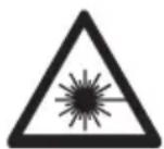
- The product is equipped with a class 2 laser. Laser signs in different languages are included in the package. If the sign on the laser is not in your local language, attach the appropriate sign to the laser.
text_image
ATTENTION LASER RADIATION DO NOT STARE INTO THE BEAM LASER DIODE Wavelength: 630 - 670 nm Max. output power: < 1 mW CLASS 2 LASER PRODUCT EN 60825-1:2014- Caution: Using equipment or procedures other than those described in these instructions could lead to exposure to dangerous radiation.
c) Battery
- To prevent battery leakage, remove the battery if you do not plan to use the product for an extended period. Leaking or damaged batteries may cause acid burns when they come into contact with skin. Always use protective gloves when handling damaged batteries.
- Keep batteries out of the reach of children. Do not leave batteries lying around, as they constitute a choking hazard for children and pets.
- Batteries must not be dismantled, short-circuited or thrown into fire. Never recharge non-rechargeable batteries. Danger of explosion!
7. Product overview
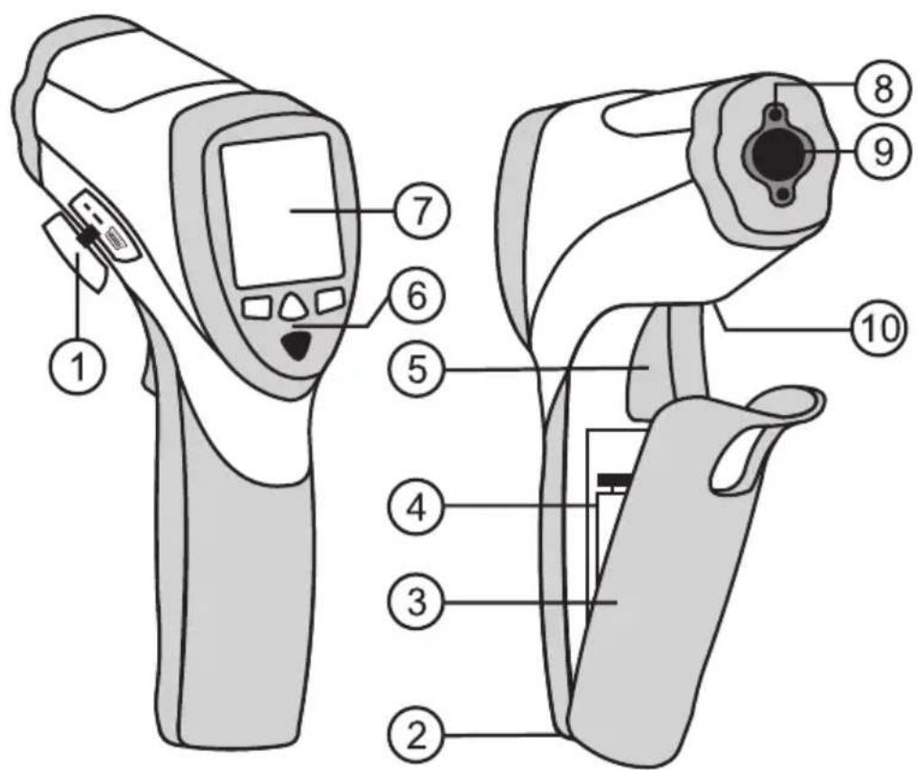
a) IR thermometer
text_image
Diagram of a medical imaging device with numbered parts for identification1 Connection for type-K thermocouple sensor and USB socket
2 Tripod thread
3 Battery compartment cover
4 Battery compartment
5 Measuring button
6 F1, F2, F3, and MODE buttons
7 Display
8 Laser outlet
9 IR sensor
10 Release button for battery compartment cover
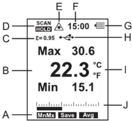
b) Display
text_image
E F SCAN HOLD 15:00 ε=0.95 Max 30.6 22.3 °C Min 15.1 A MnMx Save Avg JA Functions of the F1, F2 and F3 buttons
B Main display
C Emission level
D Operation indicator (SCAN = Measurement, HOLD = Standby)
E Laser symbol for activated target laser
F Time
G Battery level
H USB display for active interface
I Measuring unit display °Celsius/°Fahrenheit
J Bar graph
8. Product description
a) Function
Infrared thermometers measure the surface temperature of an object. The sensor on the product records the heat radiation emitted, reflected and transmitted through the object, and converts this information into a temperature value.
Emissivity is used to describe the energy emission characteristics of a material. The higher the emission level, the more radiation a material can emit. Many organic materials and surfaces have an emission level of approx. 0.95. Metallic surfaces or shiny materials have a lower emission level. This will cause an inaccurate reading. For this reason, a matt black layer of paint or matt adhesive tape should be applied to metallic shiny surfaces.
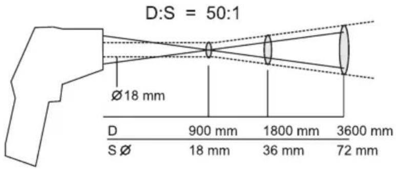
b) IR measuring optics - ratio measuring distance:measuring surface
(D:S = Distance:Spot)
In order to obtain precise measuring results, the measured object must be larger than the IR measuring spot. The measured temperature is calculated using the average temperature of the measured area. The smaller the object, the closer it must be to the thermometer. The exact size of the measuring spot is shown in the following diagram. It is also indicated on the thermometer. To ensure precise measurements, the measured object should be at least twice the size of the IR measuring spot.
The smallest measurement diameter is achieved up to a distance of 90 cm. The measurement diameter is 18 mm. However, keep sufficient distance to avoid faulty measurement due to heating of the IR thermometer.
Example: At a distance of 2 m, the measurement diameter is 40 mm.
text_image
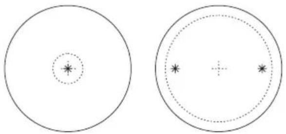
D:S = 50:1 Ø18 mm D 900 mm 1800 mm 3600 mm S Ø 18 mm 36 mm 72 mmc) Target laser
The target laser is active depending on the default setting during measurement. A warning symbol appears in the display if the laser is active (E). Never look into the laser outlet (8) during a reading.
The target laser is constructed in dual design and marks the inner, approximate edge area of the measuring surface (approx. 90%).
When both laser spots meet, the smallest measuring surface has been achieved. This is 18 mm in diameter.
With larger distances, the two laser spots move apart, analogue to the measuring surface.
natural_image
Two circular diagrams with internal dotted and solid lines, no text or symbols present9. Operation
Prior to working with the measuring device, you first have to insert the enclosed batteries.
Insert the battery as described in Section "Cleaning and Maintenance".
The IR thermometer allows individual system settings for measuring operation after initial start-up.
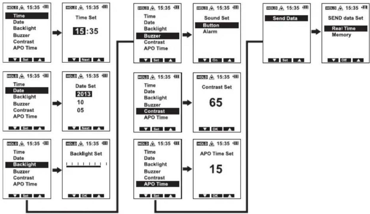
a) System settings
To enter the setting mode "SET", briefly press the measuring button (5). The measuring device switches on. In the lower display area, the main menu for the three function buttons "F1", "F2" and "F3" will appear on the display. Toggle to the next main menu or end a selected functions with the "MODE" button.
Press the "MODE" button three times until the "SET" function display appears.
Press "F2" to select the "SET" function.
text_image
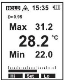
HOLD 15:35 ε=0.95 Max 31.2 28.2 °C Min 22.0 Hi Set LoThe following menu items can be selected one after the other:
flowchart
graph TD
    A["Time 15:35 Time<br>Date Backlight Buzzer Contrast APO Time"] --> B["Time Set 15:35"]
    B --> C["Backlight Buzzer<br>Contrast APO Time"]
    C --> D["Sound Set Button Alarm"]
    D --> E["Send Data"]
    E --> F["Real Time Memory"]
    G["Date 2013<br>Backlight Buzzer Contrast APO Time"] --> H["Date Set 10<br>05"]
    H --> I["Contrast APO Time"]
    I --> J["Contrast Set 65"]
    J --> K["OK"]
    L["Backlight Set Time<br>Date Backlight Buzzer Contrast APO Time"] --> M["Backlight Set OK"]
    M --> N["Contrast APO Time"]
    N --> O["Contrast Set 15"]
    O --> P["OK"]
    Q["Set"] --> R["OK"]
Exit the setup menu any time by pressing the measuring button (5). Accelerate digit settings by pressing and holding the "F1" and "F3" buttons.
b) Setting the time
Select the "Time" function with "F1" or "F3". The selected function is highlighted with a bar.
Press "F2" to confirm your selection. In the next menu, set the time in the "hh:mm" time format. Change the hour display with "F1" and "F3".
Press "F2" to continue to the minutes setting. Make the setting with "F1" and "F3". After setting, confirm the correct time with "F2" (OK). The display returns to the main menu.
c) Setting the date
Select the "Date" function with "F1" or "F3". The selected function is highlighted with a bar.
Press "F2" to confirm your selection. In the next menu, set the date in the "Year:Month:Day" format. Change the year with "F1" and "F3". Press "F2" to toggle to the next setting. Repeat the adjustment steps for the month and day. After setting, confirm the correct date with "F2" (OK). The display returns to the main menu.
d) Setting the display backlight
Select the "Backlight" function with "F1" or "F3". The selected function is highlighted with a bar.
Press "F2" to confirm your selection. In the next menu, set the display backlight in 7 levels. The level is indicated by a bar graph. Change the brightness with "F1" and "F3".
Confirm the setting with "F2" (OK). The display returns to the main menu.
e) Setting the signal beep
Select the "Buzzer" function with "F1" or "F3". The selected function is highlighted with a bar.
Press "F2" to confirm your selection. In the next menu, set the signal beep for the button tone and the alarm. Change the selection for the button tone (Button) and the alarm (Alarm) with "F1" and "F3". Turn this function on and off with "F2"; display shows "On" and "Off". Press the "MODE" button: The display returns to the main menu.
f) Setting the display contrast
Select the "Contrast" function with "F1" or "F3". The selected function is highlighted with a bar.
Press "F2" to confirm your selection. In the next menu, set the display contrast from 30 to 99% . Change the contrast with "F1" and "F3". Confirm the setting with "F2" (OK). The display returns to the main menu.
g) Setting the automatic power-off time
Select the "APO Time" function with "F1" or "F3". The selected function is highlighted with a bar.
Press "F2" to confirm your selection. In the next menu, set the automatic power-off time from 7 to 60 seconds. Change the setting with "F1" and "F3".
Confirm the setting with "F2" (OK). The display returns to the main menu.
The automatic power-off time starts counting down after the last button is pressed. The automatic power-off function is not activated in continuous measurement mode.

After powering off, all automatically collected data (current measuring value/Min/Max/Avg/Dif) will be lost. The pre-programmed system and alarm settings as well as the memory slots (1 - 30) are retained.
h) Setting interface data transmission
Select the "Send Data" function with "F1" or "F3". The selected function is highlighted with a bar.
Press "F2" to confirm your selection. In the next menu, set the transmission mode for real-time data or memory transmission. Select real-time data transmission (Real Time) or internal memory transmission (Memory) with "F1" and "F3". Turn this function on and off with "F2"; display shows "On" and "Off".
The activated interface for real-time data transmission is indicated on the display with the USB icon (7H).
Press the "MODE" button: The display returns to the main menu.

The continuous measurement function must be activated for real-time data transmission; otherwise, the automatic power-off will activate in breaks in measurement.
10. Taking measurements

In order to obtain exact measured values, the infrared thermometer has to be adjusted to the ambient temperature. Allow the device to adjust to the ambient temperature after relocation.
Prolonged measurement of high temperatures at near measuring distances leads to self-heating of the measuring device and thus to inaccurate measurements. In order to obtain exact measured values, remember the following rule of thumb: The higher the temperature, the greater the measuring distance and the shorter the measuring time.

Shiny surfaces affect the IR measurement results. To compensate, the shiny part of the surface can be covered with adhesive tape or matt black paint.
The device cannot measure through transparent surfaces such as e.g. glass. Instead, it measures the surface temperature of the glass.
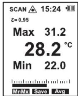
a) IR measurement
Point the laser outlet (9) at the object to be measured at a 90^ angle. Make sure the object to be measured is not smaller than the IR measuring surface of the device.
Press and hold the measuring button (5). The measured value (B) is shown in the display. The displayed value corresponds with the average surface temperature of the IR measuring surface. "SCAN" (D) appears on the display while the temperature is being measured. If the temperature measuring range is exceeded, "----" is displayed.
After releasing the measuring button (5), the last measured value is displayed until the product powers off automatically. "Hold" (D) is also displayed.
After releasing the measuring button (5), the device switches off automatically when the preset time elapses.
text_image
SCAN 15:24 ε=0.95 Max 31.2 28.2 °C Min 22.0 MnMx Save Avg
To determine the warmest/coldest spot on the object to be measured, pass the laser outlet over the entire surface area of the object while holding the measuring button (5). Additional functions allow the automatic display of the maximum value and minimum value "Min" or "Max", average value "Avg" and the difference value "Dif". These values are displayed above and below the main measurement display.

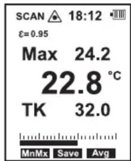
The additional functions "Min" and "Dif" are not available when a contact sensor is connected. The display shows the sensor temperature "TK" here.
b) Contact measurement

Contact temperature measurement is permissible in combination with non-rotating and voltage-free stationary objects only. Contact temperatures are only possible up to the approved temperature of the sensor. The permitted temperature of the included wire sensor is -20 to +250 °C. In order to take advantage of the entire measuring range of the measuring device, an optional wire sensor with a higher maximum temperature is required.
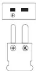
In addition to contactless IR measurement, a type-K thermocouple contact sensor may also be attached to the device. Contact measurement allows for measurement of temperature regardless of the object's material and emission level. In addition to the included wire temperature sensor, all conventional K-type thermocouple sensors with miniature plug be connected to the device.
Sensor connection
Open the side cover (1) on the device.
Plug the thermocouple plug of the sensor with correct polarity into the sensor socket. Pay attention to the "+" marking on the plug and the socket. The plug fits only in one direction into the socket.
As soon as a thermal sensor is connected with the measuring device, in measuring mode the display shows "TK" with the temperature of the sensor beneath the IR measuring value.
After measuring, remove the sensor and close the cover to prevent dirt from entering the device.

The additional functions “Min”, “Max”, “Avg” and “Dif” are not possible with contact measurement. These values pertain to IR measurements only.
text_image
SCAN 18:12 ε=0.95 Max 24.2 22.8 °C TK 32.0 MnMx Save Avgc) Additional functions
The measuring device has various additional functions which can be used individually. Select and set these additional functions with "F1", "F2" and "F3".
Press the "MODE" button to switch menu lines: The corresponding functions for the function buttons are displayed individually depending on the menu.

The additional functions “MnMx”, “Save”, “Avg”, “Mem” “E”, “Hi” or “Lo” are not possible with contact measurement. These functions pertain to IR measurements only.
Minimum, maximum, average and differential measurement function

The “Min”, “Max”, “AVG” and “Dif” measured values are saved during measurement (display shows “SCAN”) regardless of the currently displayed measuring function and are retained until the measuring device switches off automatically. Set the automatic power-off time from 7 to 60 seconds for convenient reading of measurement values.
During breaks in measurement, toggle between and read these values (display shows "HOLD"). During measurement, it is not possible to toggle between the "MnMx" and "Avg" function. You can select a display either before or after measurement.
Turn the measuring device on by briefly pressing the measuring button (5).
Select the desired display "MnMx/Avg" with "F1" or "F3" and conduct the measurement. After measuring, release the measuring button.
Within the preset power-off time, enter the "MnMx/Save/Avg" setting mode with the "MODE" button.
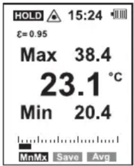
Press "F1" to display the minimum and maximum values.
Press "F3" to display the average and difference values. The average value "Avg" is calculated from the last measurement period.
The difference value “Dif” shows the difference between the minimum and maximum values.
text_image
HOLD 15:24 ε=0.95 Max 38.4 23.1 °C Min 20.4 MnMx Save Avg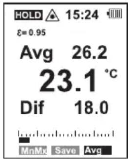
text_image
HOLD 15:24 ε=0.95 Avg 26.2 23.1 °C Dif 18.0 MnMx Save AvgSaving measured values "Save"
The “Save” function allows you to save up to 30 IR measure values in the internal memory. The stored data can be read on the device via the “Mem” function or transferred to a computer via USB.

The storage of the measured data is only possible during breaks in measurement (display shows "HOLD"), before the measuring device switches off automatically.
Set the automatic power-off time from 7 to 60 seconds for convenient storage of measurement values.
Turn the measuring device on by briefly pressing the measuring button (5) and conduct the measurement.
When the desired value is shown, release the measuring button.
Within the preset power-off time, enter the "MnMx/Save/Avg" setting mode with the "MODE" button.
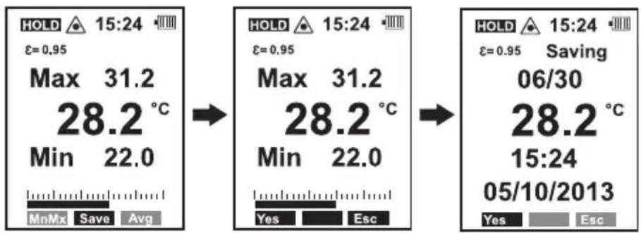
Press "F2" to save the measured value.
text_image
HOLD 15:24 ε=0.95 Max 31.2 28.2 °C Min 22.0 MnMx Save Avg HOLD 15:24 ε=0.95 Max 31.2 28.2 °C Min 22.0 Yes Esc HOLD 15:24 ε=0.95 Saving 06/30 28.2 °C 15:24 05/10/2013 Yes EscSelect "Yes" to save the value.
While the device is storing the value, the display shows all the parameters such as storage space number, measured value, date and time for approx. 2 seconds. The display then returns to the main menu. A further value can then be measured and stored.
To interrupt saving, select the "Esc" function. The display returns to the main menu after interruption.
The memory slots are filled automatically in sequence until all 30 are occupied. If there is no longer any free memory available, an error message appears ("ERR").
In order to be able to save new measurement data, delete individual slots, the entire memory or transfer the saved data to a computer.
Reading and deleting memory slots is described in the following section.
Reading and deleting memory slots
The "Mem" function allows you to read and delete occupied memory slots on the display.
Turn the measuring device on by briefly pressing the measuring button (5).
Within the preset power-off time, enter the "Unit/Mem/E" setting mode with the "MODE" button.
Press "F2" to access the memory "Mem".
Reading data
Select the desired memory slot with "F1" or "F3". The data is displayed with the memory slot number and the number of occupied slots (example: Storage slot 02 of 26 occupied slots).
Press "MODE" to return to the settings menu.
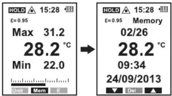
text_image
HOLD 15:28 ε=0.95 Max 31.2 28.2 °C Min 22.0 Unit Mem E → HOLD 15:28 ε=0.95 Memory 02/26 28.2 °C 09:34 24/09/2013 Del ▲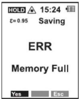
text_image
HOLD ▲ 15:24 ε=0.95 Saving ERR Memory Full Yes EscDeleting data
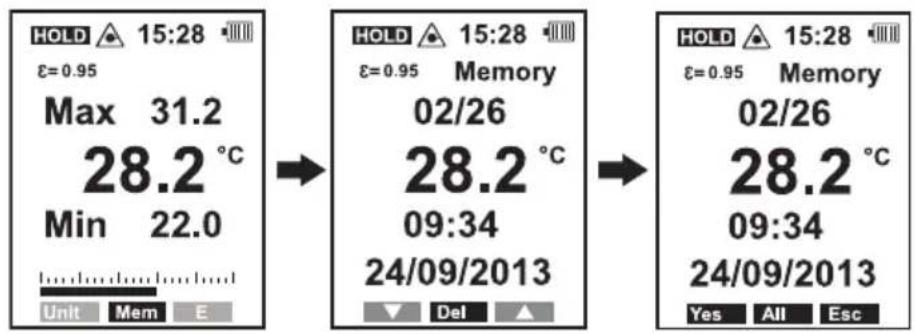
Select the desired memory slot with "F1" or "F3".
To delete, select the menu point "Del" with "F2".
Delete an individual slot by selecting the "Yes" function with "F1".
Delete the entire memory by selecting the "All" function with "F2".
Exit the deletion menu with the "Esc" function or the "MODE" button.
text_image
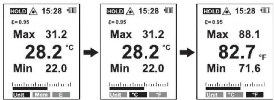
HOLD 15:28 ε=0.95 Max 31.2 28.2 °C Min 22.0 Unit Mem E HOLD 15:28 ε=0.95 Memory 02/26 28.2 °C 09:34 24/09/2013 Del HOLD 15:28 ε=0.95 Memory 02/26 28.2 °C 09:34 24/09/2013 Yes All EscSetting the temperature unit
Set the temperature unit for display with the "Unit" function.
Turn the measuring device on by briefly pressing the measuring button (5).
Within the preset power-off time, enter the "Unit/Mem/E" setting mode with the "MODE" button.
Press "F1" to access the settings menu "Unit".
Select the unit you wish to display the measured values in.
^ C = degrees Celsius
°F = degrees Fahrenheit
text_image
HOLD 15:28 ε=0.95 Max 31.2 28.2 °C Min 22.0 Unit Mem E HOLD 15:28 ε=0.95 Max 31.2 28.2 °C Min 22.0 Unit °C °F HOLD 15:28 ε=0.95 Max 88.1 82.7 °F Min 71.6 Unit °C °FPress "MODE" to return to the settings menu.
The change affects all measured values. The stored data are also displayed in the selected unit and switched in the event of a new setting.
Setting the emissivity
The emission level can be set from 0.10 to 1.00 individually or via an integrated material table with common metal surfaces. Thus, different materials and surfaces can be measured with exact results.
Turn the measuring device on by briefly pressing the measuring button (5).
Within the preset power-off time, enter the "Unit/Mem/E" setting mode with the "MODE" button.
Press "F3" to access the settings menu "E".
Setting the emissivity individually
The emission level can be set between 0.10 to 1.00 in intervals of 0.01 with "F1" and "F3".
Press the measuring button (5) or "MODE" to confirm your input.
text_image
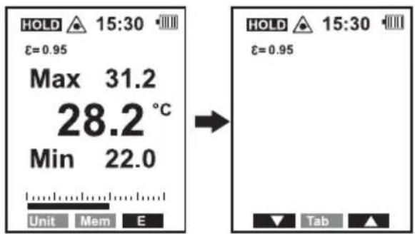
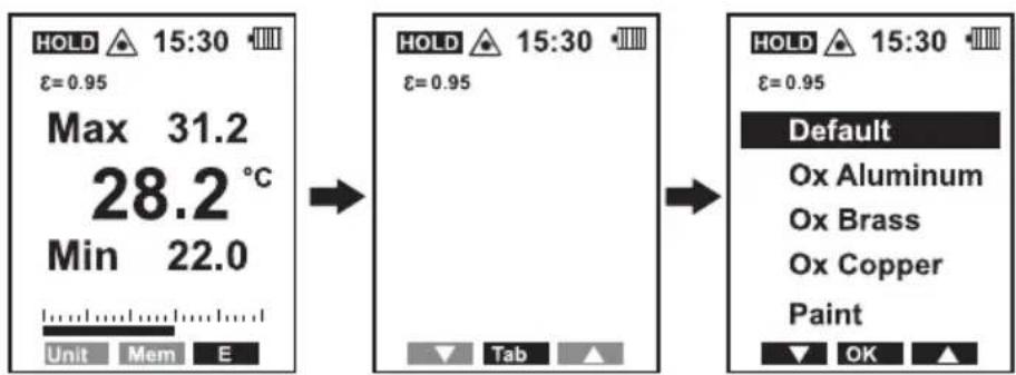
HOLD ▲ 15:30 • ε=0.95 Max 31.2 28.2 °C Min 22.0 Unit Mem E → HOLD ▲ 15:30 • ε=0.95 ▼ Tab ▲The emission level can be set using an integrated material table for common metals.
Press "F2" to select the "Tab" function. A material table is displayed.
Select the material at hand with "F1" and "F3". The selected material is highlighted with a bar. The emission level changes accordingly.
| Default Emission value of most materials (0.95) |
| Ox Aluminum Aluminium oxide (0.30) |
| Ox Brass Brass oxide (0.50) |
| Ox Copper Copper oxide (0.60) |
| Paint Painted surface (0.93) |
text_image
HOLD 15:30 ε=0.95 Max 31.2 28.2 °C Min 22.0 Unit Mem E HOLD 15:30 ε=0.95 Tab HOLD 15:30 ε=0.95 Default Ox Aluminum Ox Brass Ox Copper Paint OKConfirm the selection with "OK" (Button "F2"). Press the measuring button (5) or "MODE" to exit the settings menu.

Following the technical data you will find a table with common materials and their emission levels.
Many organic materials have an emissivity of 0.95. Therefore, the default emission level setting is 0.95.
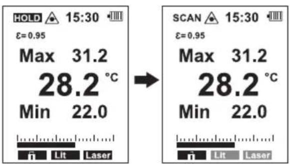
Continuous measurement
The measuring device is equipped with a continuous measurement mode.
Turn the measuring device on by briefly pressing the measuring button (5).
Select the settings menu in Milit Laser the pre-set power-off time.
Turn continuous measurement on/off with "F1". Press the button once to turn on the function and again to turn it off.
text_image
HOLD 15:30 ε=0.95 Max 31.2 28.2°C Min 22.0 ← SCAN 15:30 ε=0.95 Max 31.2 28.2°C Min 22.0 ← Lit Laser
Continuous measurement off

Continuous measurement on

When the continuous measurement function deactivated, the measuring button (5), the "MODE" button and the automatic power-off function are out of operation.
Display backlight (quick setting)
You can set the display backlight via the direct menu.
Turn the measuring device on by briefly pressing the measuring button (5).
Select the settings menu in Milit to Laser the pre-set power-off time.
Set the display backlight with "F2" via the "Lit" function. Each time you press the button, the backlight brightens one step and starts over after the brightest level.
Turning the laser on/off
The target laser can be turned on and off. Turning off the laser is necessary to measure highly shiny or reflective surfaces to prevent uncontrolled beam deflection.
Turn the measuring device on by briefly pressing the measuring button (5).
Select the settings menu in Lit to Laser the pre-set power-off time.
Turn the target laser on/off with "F3" via the "Laser" function. Press the button once to turn on the function and again to turn it off. The activated laser function is indicated with the laser icon (E) on the display.

Never look directly into the laser outlets. Always observe the safety information included in these operating instructions.
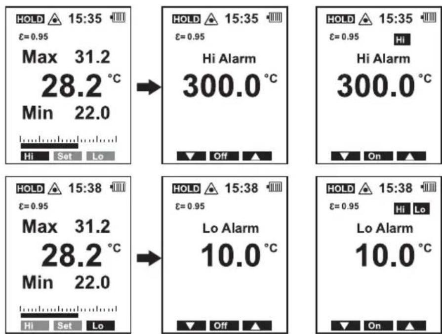
Alarm function "Hi/Lo"
The measuring device is equipped with an optical and acoustic alarm function. The alarm can be set and activated separately for over-temperature "Hi" and under-temperature "Lo".
The alarm sounds when the set temperature value is exceeded or fallen below. The symbol (Hi/Lo) starts to flash and the display lights up red. The alarm is triggered when the lower alarm value "Lo" is fallen below or the upper alarm value "Hi" exceeded.
Turn the measuring device on by briefly pressing the measuring button (5).
Select the settings menu "Hi/Set/Lo" with the "MODE" button within the pre-set power-off time.
Setting the alarm
Select with "F1" the settings menu for the upper alarm value "Hi" or with "F3" the settings menu for the lower alarm value "Lo".
Set the alarm value with "F1" and "F3". Press and hold the button. This will change the decimal place after a short time to more quickly set larger values.
The smallest setting interval is 0.1 up to 999.9 and from 1000 in intervals of 1.
Turn the alarm on/off with "F2". The menu function for "F2" shows the current status of each alarm. Press the button to change the status:
Off = disabled
On = activated
In addition, the corresponding alarm function is indicated on the display with the symbol "Hi" or "Lo".
Press the measuring button (5) or "MODE" to confirm your input. The settings are saved.
text_image
HOLD 15:35 ε=0.95 Max 31.2 28.2 °C Min 22.0 Hi Set Lo HOLD 15:35 ε=0.95 Hi Alarm 300.0 °C Off ▲ HOLD 15:35 ε=0.95 Hi Hi Alarm 300.0 °C On ▲ HOLD 15:38 ε=0.95 Max 31.2 28.2 °C Min 22.0 Hi Set Lo HOLD 15:38 ε=0.95 Lo Alarm 10.0 °C Off ▲ HOLD 15:38 ε=0.95 Hi Lo Lo Alarm 10.0 °C On ▲During measurement, a signal sounds when the corresponding alarm level is reached, the display lights up red and the symbol "Hi" or "Lo" starts to flash.
The set alarm values are retained after power-off.
Data transmission via USB
The measuring device is equipped with a USB interface for the transmission and storage of data on a computer.
Proceed as follows to connect the infrared thermometer to your computer:
Start up your computer with Windows® 2000 or higher.
Insert the supplied software CD into a CD drive and follow the instructions on the screen.
If the automatic program installation does not start, select the CD drive in Explorer and start the installation program "setup.exe" manually. Follow the on-screen instructions.
After successful program installation, install the USB driver manually. To do so, select the CD drive in Explorer and open the file "USB Driver". Start the installation program "cp210xVCPInstaller.exe" manually. Follow the on-screen instructions.
Activate the USB interface from the device in the system settings menu "Set" under "Send Data".
Activate/deactivate the continuous measurement function to prevent automatic power-off during any breaks in measurement. The data transfer takes place only when the measuring device is switched on.
Open the side cover (1) on the device. Plug the USB cable provided into the Mini-USB socket on the side and connect the other end of the cable to a free USB port of your computer.
The computer automatically detects a new device. After successful installation, you can start the measurement software.
The display shows "Connected" when the data link is successful.
The program settings and operation can be found in the software's help menu (Help). Infrared readings as well as contact temperature readings are transferred to your computer.
After the data transfer, deactivate continuous measurement and turn off the interface from the measuring device.
11. Care and cleaning
a) General information
Apart from occasional cleaning and battery replacement, the device requires no servicing.
Always observe the following safety instructions before cleaning the device.
b) Cleaning the lens
Remove loose particles with clean compressed air and wipe off remaining residues with a fine lens brush. Clean the surface of the lenses using a lens cloth or a soft, lint-free cloth. The cloth can be moistened with water or a lens cleaning solution to remove fingerprints and other residues. Do not use any acidic, alcoholic or other solvents or rough, linty cloth to clean the lens. Avoid applying too much pressure when cleaning the lens.
c) Cleaning the housing
Do not use scouring, chemical or aggressive cleaning agents such as benzene, alcohol or such like. These might attack the surface of the device. In addition, the vapours emitted by these substances are explosive and harmful to your health. Do not use sharp-edged tools, screwdrivers or metal brushes to clean the device.
To clean the device and/or the sensor, use a clean, lint-free, antistatic and slightly damp cleaning cloth.
d) Inserting/changing the battery
For initial start-up the battery enclosed must be inserted. Press the release button on the bottom of the device to open the battery compartment cover (10). The battery compartment cover is unlocked. Open the battery compartment cover (3) to the front. Connect the battery.
To change the battery, remove the used battery from the battery clip and connect a new battery of the same type to the battery clip. The battery clip is constructed so the battery can be connected only with the correct polarity. Do not use force when plugging in the battery.
Close the battery compartment by closing the battery compartment cover (3). Make sure the cables are not pinched and that the lock clicks into place.
Replace the battery when the battery icon (G) in the display shows less than two bars.

text_image
Full EmptyDo not leave flat batteries in the device. Even batteries protected against leaking can corrode and thus release chemicals which may be detrimental to your health or destroy the device.
12. Troubleshooting
The IR thermometer you have purchased was designed using the latest technology and is safe to use.
However, problems and malfunctions may still occur.
Therefore, we would like to describe here how you can solve any problems.

Always follow the safety information.
| Error Possible cause | |
| The device does not work. Is the battery empty? | |
| Is the wrong emission level set? | |
| Is the lens dirty? | |
| Incorrect measurement display. | Is the measuring surface covered with a glass pane? |
| Was the permissible operating temperature exceeded or fallen below? |
13. Disposal
a) Product
Electronic devices are recyclable waste and must not be disposed of in the household waste. Always dispose of the product according to the relevant statutory regulations. Remove any inserted batteries and dispose of them separately from the product.
b) Batteries

You are required by law to return all used batteries (Battery Directive). Batteries must not be placed in household waste.
Batteries containing hazardous substances are labelled with this symbol to indicate that disposal in household waste is forbidden. The abbreviations for heavy metals in batteries are: Cd = Cadmium, Hg = Mercury, Pb = Lead (indicated on the battery, e.g. below the trash icon on the left).
Used batteries can be returned to local collection points, our stores or battery retailers.
You thus fulfil your statutory obligations and contribute to the protection of the environment.
14. Technical data
Power supply....9 V block battery
Response time....150 ms
Emission level....0.1 – 1.00 (adjustable)
IR measurement range....-50 to +1200 °C (-58 to +2192 °F)
Contact measurement range....-50 to +1370 °C (-58 to +2498 °F)
Resolution....0.1 °C/°F
IR optics....50:1
Laser....output <1 mW, laser class 2, wavelength 630 - 670 nm
Operating conditions....0 to +50 °C, 10 – 90 % RH
Storage conditions....-10 to +60 °C, <80 % RH
System requirements....Windows® 2000 and higher
Weight 330 g
Dimensions (W x H x D) 204 x 52 x 155 mm
Measuring tolerances
The accuracy is valid for one year at a temperature of +23 to +25 °C (+73 to +77 °F), and at a relative humidity of less than 75%, non-condensing.
Infrared temperature measurement range
| Measurement range °C Accuracy Reproducibility | |
| -50 to +20 °C ± 3 °C ± 1.5 °C | |
| +20 to +500 °C ±1 % ±1 °C | ±0.5 % or ±0.5 °C |
| +500 to +1000 °C ± 1.5 % | |
| +1000 to +1200 °C ± 2.0 % ± 1.0 % |
| Measurement range °F Accuracy Reproducibility | ||
| -58 to +68 °F ± 5.4 °F ± 2.7 °F | ||
| +68 to +932 °F ±1 % ±1.8 °F | ±0.5 % or ±0.9 °F | |
| +932 to +1832 °F ± 1.5 % | ||
| +1832 to +2192 °F | ± 2.0 % ± 1.0 % | |
K-type contact temperature measurement
| Measurement range °C Accuracy | |
| -50 to 0 °C ± 2 °C | |
| 0 to +1370 °C ±(0.5 % + 1.5 °C) | |
| Measurement range °F Accuracy | |
| -58 to +32 °F ± 3.6 °F | |
| +32 to +2498 °F ±(0.5 % + 3 °F) |
Emissivity of different surfaces
The emission levels listed in the table are approximate values. Parameters such as the shape and characteristics of the material can affect the emissivity of an object.
The measuring device is preset with an emission level of 0.95. This level matches most non-metallic materials. The IR measuring method is suitable for bare metals only to a limited extent and requires special surface treatment (e.g. matt insulation tape etc.) or setting the appropriate emission level.
| Surface Emission level | Surface Emission level | ||
| Aluminium, bare 0.04 Copper oxide 0.60 | |||
| Aluminium oxide 0.30 Brass oxide 0.50 | |||
| Asphalt 0.90 - 0.98 Varnish, matt | 0.93 - 0.97 | ||
| Concrete | 0.94 Food | 0.93 - 0.98 | |
| Ice | 0.96 - 0.98 Human skin | 0.98 | |
| Ferric oxide 0.78 - 0.82 Plastic | 0.94 | ||
| Paint | 0.93 Paper | 0.97 | |
| Hard plaster | 0.80 - 0.90 Sand | 0.90 | |
| Glass/porcelain | 0.92 - 0.94 Textiles 0.90 | ||
| Rubber, black | 0.94 Water | 0.92 - 0.96 | |
| Wood | 0.94 Bricks, plastering | 0.93 - 0.96 | |
Page
France (email): technique@conrad-france.fr
text_image
Diagram of a medical imaging device with numbered parts for identificationtext_image
E F SCAN HOLD 15:00 ε=0.95 Max 30.6 22.3 °C Min 15.1 A MnMx Save Avg J(D:S = Distance:Spot = ratio distance:surface de mesure)
natural_image
Two circular diagrams with internal dotted and solid lines, no text or symbols present9. Mise en service
text_image
SCAN 18:12 ε=0.95 Max 24.2 22.8 °C TK 32.0 MnMx Save Avg
text_image
HOLD 15:24 ε=0.95 Max 38.4 23.1 °C Min 20.4 MnMx Save Avg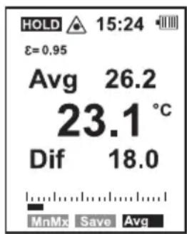
text_image
HOLD 15:24 ε=0.95 Avg 26.2 23.1 °C Dif 18.0 MnMx Save Avgtext_image
HOLD 15:24 ε=0.95 Max 31.2 28.2 °C Min 22.0 MnMx Save Avg HOLD 15:24 ε=0.95 Max 31.2 28.2 °C Min 22.0 Yes Esc HOLD 15:24 ε=0.95 Saving 06/30 28.2 °C 15:24 05/10/2013 Yes Esctext_image
HOLD 15:24 ε=0.95 Saving aines ERR Memory Full Yes Esctext_image
HOLD 15:28 ε=0.95 Max 31.2 28.2 °C Min 22.0 Unit Mem E → HOLD 15:28 ε=0.95 Memory 02/26 28.2 °C 09:34 24/09/2013 Del ▲text_image
HOLD 15:28 ε=0.95 Max 31.2 28.2 °C Min 22.0 Unit Mem E HOLD 15:28 ε=0.95 Max 31.2 28.2 °C Min 22.0 Unit °C °F HOLD 15:28 ε=0.95 Max 88.1 82.7 °F Min 71.6 Unit °C °Ftext_image
HOLD 15:30 ε=0.95 Max 31.2 28.2 °C Min 22.0 Unit Mem E HOLD 15:30 ε=0.95 Tab ▲ HOLD 15:30 ε=0.95 Default Ox Aluminum Ox Brass Ox Copper Paint OK ▲text_image
HOLD 15:35 ε=0.95 Max 31.2 28.2 °C Min 22.0 Hi Set Lo HOLD 15:35 ε=0.95 Hi Alarm 300.0 °C Off ▲ HOLD 15:35 ε=0.95 Hi Hi Alarm 300.0 °C On ▲ HOLD 15:38 ε=0.95 Max 31.2 28.2 °C Min 22.0 Hi Set Lo HOLD 15:38 ε=0.95 Lo Alarm 10.0 °C Off ▲ HOLD 15:38 ε=0.95 Hi Lo Lo Alarm 10.0 °C On ▲text_image
Diagram of a medical imaging device with numbered parts for identificationtext_image
E F SCAN HOLD 15:00 ε=0.95 Max 30.6 22.3 °C Min 15.1 A J MnMx Save Avgnatural_image
Two circular diagrams with internal dotted lines and asterisk symbols, no text or labels present.9. Ingebruikname
text_image
SCAN 18:12 ε=0.95 Max 24.2 22.8 °C TK 32.0 MnMx Save Avgc) Extra functies
text_image
HOLD 15:24 ε=0.95 Max 38.4 23.1 °C Min 20.4 MnMx Save Avg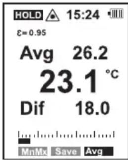
text_image
HOLD 15:24 ε=0.95 Avg 26.2 23.1 °C Dif 18.0 MnMx Save AvgMeetwaarden opslaan "Save"
text_image
HOLD 15:24 ε=0.95 Max 31.2 28.2 °C Min 22.0 MnMx Save Avg HOLD 15:24 ε=0.95 Max 31.2 28.2 °C Min 22.0 Yes Esc HOLD 15:24 ε=0.95 Saving 06/30 28.2 °C 15:24 05/10/2013 Yes Esctext_image
HOLD ▲ 15:24 ■■■ ε=0.95 Saving ERR Memory Full Yes Esctext_image
HOLD 15:28 ε=0.95 Max 31.2 28.2 °C Min 22.0 Unit Mem E → HOLD 15:28 ε=0.95 Memory 02/26 28.2 °C 09:34 24/09/2013 Del ▲Gegevens wissen
text_image
HOLD ▲ 15:30 ■■■ ε=0.95 Max 31.2 28.2 °C Min 22.0 Unit Mem E → HOLD ▲ 15:30 ■■■ ε=0.95 ▼ Tab ▲text_image
HOLD 15:30 ε=0.95 Max 31.2 28.2 °C Min 22.0 Unit Mem E HOLD 15:30 ε=0.95 Tab HOLD 15:30 ε=0.95 Default Ox Aluminum Ox Brass Ox Copper Paint OKtext_image
HOLD 15:35 ε=0.95 Max 31.2 28.2 °C Min 22.0 Hi Set Lo HOLD 15:35 ε=0.95 Hi Alarm 300.0 °C Off ▲ HOLD 15:35 ε=0.95 Hi Hi Alarm 300.0 °C On ▲ HOLD 15:38 ε=0.95 Max 31.2 28.2 °C Min 22.0 Hi Set Lo HOLD 15:38 ε=0.95 Lo Alarm 10.0 °C Off ▲ HOLD 15:38 ε=0.95 Hi Lo Lo Alarm 10.0 °C On ▲This is a publication by Conrad Electronic SE, Klaus-Conrad-Str. 1, D-92240 Hirschau (www.conrad.com).
All rights including translation reserved. Reproduction by any method, e.g. photocopy, microfilming, or the capture in electronic data processing systems require the prior written approval by the editor. Reprinting, also in part, is prohibited. This publication represents the technical status at the time of printing.
Copyright 2018 by Conrad Electronic SE.
Copyright 2018 by Conrad Electronic SE.
Copyright 2018 by Conrad Electronic SE.