K202 - Thermometer VOLTCRAFT - Free user manual and instructions
Find the device manual for free K202 VOLTCRAFT in PDF.
| Product type | Digital thermometer with data logger (Data Logger) |
| Brand | Voltcraft |
| Model | K202 (also designated 306) |
| Measurement range | -200°C to +1370°C / -328°F to +2498°F (with type K probe) |
| Measurement range with supplied probes | -50°C to +200°C / -58°F to +392°F |
| Accuracy (device only) | ±(0.2% + 1°C) from -200°C to +200°C; ±(0.5% + 1°C) from +200°C to +400°C; ±(0.2% + 1°C) from +400°C to +1370°C |
| Resolution | 0.1°C from -200°C to +200°C; 1°C beyond |
| Display | Multi-function LCD: 1 large display (3 3/4 digits) + 2 sub-displays (3 3/4 digits), symbols and units |
| Main functions | Measurement T1, T2, difference T1-T2; MAX/MIN; HOLD; REC recording; time display; PC connection (RS-232) with ThermoLog software |
| Power supply | 9V battery type NEDA 1604 or 6F22 (alkaline); 9V DC mains adapter (optional) |
| Dimensions (L x W x H) | 184 x 64 x 30 mm (without cables) |
| Weight | 210 g (with battery) |
| Operating temperature | 0°C to +50°C |
| Storage temperature | -10°C to +60°C (without battery) |
| Relative humidity | 0 to 80% (non-condensing) |
| PC interface | RS-232 via 3.5 mm stereo jack; cable to 9-pin COM provided |
| Included software | ThermoLog on floppy disk (compatible with Windows 95/98/NT/2000/XP) |
| System requirements | 486 DX2/100, 16 MB RAM, 5 MB hard disk, 800x600 resolution, free COM port |
| Maintenance | Clean with a dry, lint-free, antistatic cloth; annual calibration recommended via CAL capacitor |
| Safety | Compliant with EN 61010-1; max voltage between device and earth: 24 V~ or 60 V=; do not use in explosive atmospheres or near strong magnetic fields |
| Spare parts / Repairability | Standard 9V battery; type K probes (TP-K01 supplied); interface cable; mains adapter (optional) |
Frequently Asked Questions - K202 VOLTCRAFT
User questions about K202 VOLTCRAFT
0 question about this device. Answer the ones you know or ask your own.
Ask a new question about this device
Download the instructions for your Thermometer in PDF format for free! Find your manual K202 - VOLTCRAFT and take your electronic device back in hand. On this page are published all the documents necessary for the use of your device. K202 by VOLTCRAFT.
USER MANUAL K202 VOLTCRAFT
Due to technical changes the following chapters of the operating instructions have been changed.
System requirements:
- Operating system Windows® NT/2000/XP
CPU clock rate 150 MHz - 64 MByte memory
approx.10 MByte available hard disc space
one available USB port
Software installation:
- Establish connection between PC (free COM port) and thermometer
Turn thermometer on and start up PC - Place the CD included in the delivery in the appropriate drive of your computer.
- After inserting the CD, the installation program will automatically start. Depending on the individual system configuration a manual start of the installation program might be required. For this, run the CD's 'setup.exe' file.
- The installation program will now semi-automatically guide you through the program installation process which allows, if required, selection of an installation directory path different to the standard preset path. The program will be installed in the program folder 'SE305' and displayed with the symbol 'SE305'.
Data transfer:
Starting the software
-
On the left side of the window the "Control Panel" is displayed. It facilitates easy use of the measurement device from the comfort of the PC. To the right is the display for the tables and graphs.
The selected port must be set via the COM Port" menu item in the function field.
Once the measurement device is properly connected to the PC, an info line with the following content will show up above the window's margin at the bottom: -
Com 1 (depending on the port selected).
ON Connection -
Real-time logging:
- For real-time logging, the sampling rate must be set in minutes (MM) and seconds (SS) before starting the measurement. Further settings can be adjusted via the menu item, Option Graph Customization ^1 .
- Start logging by pressing „RUN" in the „Real Time" sub menu.
The tables and graphs will now show the measurement values.
Readout from the data logger:
- After a connection between measurement device and PC is established the values collected in the measurement device can be read out.
- For this, "Data Logger" has to be selected from the function field.
Data transmission will then be started automatically and the recorded values will be displayed in table form and in graphs.

For further help see the documents SE305Help.doc or SE305Help.html in the software program's program folder.
We ask for your understanding.
Your VOLTCARAFT team
F REMARQUE IMPORTANTE !!!
NL BELANGRIJKE INFORMATIE !!!
Copyright 2009 by Voltcraft®
Impressum /legal notice in our operating instructions
These operating instructions are a publication by Volcraft®, Lindenweg 15, D-92242 Hirschau/Germany, Phone +49 180/586 582 7 (www.volcraft.de).
All rights including translation reserved. Reproduction by any method, e.g. photocopy, microfilming, or the capture in electronic data processing systems require the prior written approval by the editor. Reprinting, also in part, is prohibited.
These operating instructions represent the technical status at the time of printing. Changes in technology and equipment reserved.
Copyright 2009 by Voltcraft®
Copyright 2009 by Voltcraft®
Copyright 2009 by Voltcraft®
01_0209_01/HK
D
These operating instructions are an integral part of this product. They also contain important instructions on commissioning and handling. Please also take them into consideration when passing the product on to third parties.
Please keep these Operating Instructions carefully for future reference.
The Table of Contents on page 22 contains a list of the various subjects stating the page numbers in question.
F
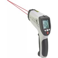
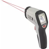
Model: Two Channel, K type thermometer
Druckersymbol = Print
Druckersymbol = Print
by purchasing the digital thermometer 306, you now have a state-of-art temperature meter.
The device has been designed according to DIN VDE 0411, part 1 for measuring equipment = EN 61010-1.
Moreover, it is EMC-tested (for indoor use) and thus meets the requirements of the applicable European and national Directives. Conformity has been proved; the appropriate documents (declaration) are kept at the manufacturer's.
To make sure this state is maintained and to ensure safe operation, it is essential that you - the user - adhere to these operating instructions!
For a fast response of your technical enquiries please contact or consult our Technical Advisory Service:
Germany: Tel. + 49 9604 / 40 88 80
Fax + 49 9604 / 40 88 48
E-mail: tkb@conrad.de
Mon to Thurs 8.00am to 4.30pm
Fri 8.00am to 2.00pm
Usage for the intended purpose:
Measurement of temperatures in the range from -200^ to +1370^ or -328^ to +2498^ via one or two (independent) external temperature sensor(s) (K type).
Measurement of temperatures in the range from -50^ to max. +200^ or -58^ to +392^ using the enclosed K-Type temperature sensors.
Bidirectional signal transmission to an IBM compatible PC running under Windows '98 or a more recent version via the serial interface, with data logging function.
Measurement under adverse ambient conditions is not admissible
Such adverse ambient conditions are:
- moisture or excessive (air) humidity,
- dust and combustible gases, vapours or solvents,
- Thunderstorms or thundery conditions, such as strong electromagnetic fields, etc.
Any use deviating from that described above results in product damage; it moreover involves danger, e.g. short-circuits, fire, electric shocks etc. The entire product must not be changed or modified!
It is essential to adhere to the safety provisions!
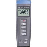
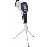
Control elements
(Illustration, refer to fold-out page)
- Measuring input "+" and "-", channel T1, for a K-type temperature sensor
- Measuring input for channel T2, for a K-type temperature sensor.
- Multifunction display with 1 × 3-3/4 digit big display and 2 × 3-3/4 digit (smaller) subdisplays and indication of the functions and units.
- On/off push-button
- "TIME" push-button for indication of the preset time of day.
- Record push-button "REC".
- "MAX MIN"-push button for measurement-recording of minimum and maximum values.
- "HOLD" push-button to hold a measured value (in case of fast changing measuring signals).
- Change-over push-button for changing the unit over from "°C" to "°F" and vice versa.
- Trimmer for offset calibration.
- Serial RS 232 interface (3.5 mm stereo jack bush)
- Supply socket for connection of a suitable mains adapter, "-" inside.
- Tripod mounting thread bush
- Cover for battery compartment underneath
Table of Contents
Page
Introduction 20
Usage for the intended purpose 20
Control elements (fold-out page) 21
Table of Contents 22
Safety Provisions 22
Presentation, system prerequisites 24
Handling, start-up 24
PC connection, software installation 28
Measuring procedure 29
Disposal 33
Troubleshooting 34
Service and maintenance. 34
Technical data, measuring tolerances 34
Safety provisions
Any damage caused by non-compliance with the operating instructions rule out your warranty claim! We shall not be held liable for consequential damage resulting from such non-compliance.
We shall not be held liable for material or personal damage resulting from improper handling or non-compliance with the safety provisions. In such cases, any warranty claims are ruled out.
The digital thermometer 306 left our factory in perfectly safe technical condition. To maintain this condition and to ensure safe operation, the user must comply with the safety provisions and warning instructions ("Attention" and "Note!") contained in these Operating Instructions. The following symbols must be observed:

= Read the Operating Instructions
- Measuring devices and accessories are not toys, and thus must be kept away from children!
-
When used in industrial plants, the Provisions for the Prevention of Accidents of the Association of Industrial Employers' Liability Insurance Associations for Electrical Installations and Equipment must be complied with.
-
In schools, training centres, hobby and do-it-yourself workshops, operation of timer switches must be supervised by responsible, well-trained staff.
-
When handling the thermometer, make sure that the measurement fluids are de-energized! Particular caution is required when handling voltages exceeding 25 V AC or 35 V DC. When touching live electrical conductors, you may suffer a potentially fatal electric shock even at such voltages!
-
Before any measurement, check your measuring device or your temperature sensors for damage.
-
The voltage between measuring device and ground must never exceed 24 VACrms or 60 VDC.
-
Do not operate the measuring device in rooms or in adverse ambient conditions which involve (or might involve) inflammable gases, vapours or dust. For your own safety, it is essential to prevent the measuring device or the measuring lines from getting damp or wet. Operation should be avoided in the immediate vicinity of
a) powerful magnetic fields (loudspeakers, magnets)
b) electromagnetic fields (transformers, motors, coils, relays, contactors, solenoids etc.)
c) electrostatic fields (charge/discharge)
d) Transmission aerials or RF generators
-
Do not use the digital thermometer just before, during or just after a thunderstorm (lightning! / high-energy overvoltages!). Make sure that your hands, shoes, garments, the floor, the measuring device, the measuring lines, circuits and circuitry components are dry.
-
If safe operation can no longer be reasonably assumed, the unit must be decommissioned and protected against involuntary operation. Safe operation cannot be reasonably assumed if
-
the unit shows visual traces of damage.
- the unit no longer functions and
- after extended storage under unfavourable conditions or
-
after severe strain during transit.
-
Never switch on the measuring device immediately after having taken it from a cold into a warm room. Under certain circumstances, the condensate thus developed may destroy the device. Allow the device to adjust to room temperature before switching on.
Presentation, system prerequisite(s)
This digital thermometer 306 with PC connection has several smart features to supplement many measurements:
The "MAX MIN" function, for example, enables determination and recording of the highest or lowest measured value. The "HOLD" function serves to record fast changing measured values (for test records). The "TIME" push-button helps you interrogate the (preset) current time-of-day (with date). The "REC" push-button starts pickup of measured values. The ^ C / ^ push-button offers the choice between two units: the "British" in Fahrenheit, and the "metric" in Centigrade. If you actuate the "MAX MIN" push-button while switching on the device, you can access the setup menu; but this will be described in more detail later on.
The measuring range extends from -200^ to +1370^ or from -328^ to +2498^ . However, the temperature range of the enclosed sensors is limited to -50^ to +200^ .
A bidirectional connection to the PC is established via the (serial) interface cable supplied with the device. Installation of the appropriate software on the PC enables the digital thermometer to communicate with the PC.
The digital thermometer 306 can be used for a wide range of hobby applications and in professional or school environments.
The following prerequisites for installation and operation of the software must be fulfilled:
Min. 486 DX2/100 with 16 MB RAM or faster/bigger
Min. Windows '95 or '98 or NT 4.0 or a more recent version
Resolution min. 800 × 600 , and finally 5 MB of free HD space.
Handling, start-up
A Battery installation - replacement
To enable your measuring device to work properly, it must be equipped with a 9 V monobloc battery. If the battery replacement symbol on top left appears in the display, you must replace the battery. To this effect, proceed as follows:
- Disconnect your measuring device from the measuring circuit and from the PC,
- remove the temperature sensors from the measuring device,
- switch it off and
- carefully push the battery compartment cover off in the direction of the arrow.
- Disconnect the discharged battery from the terminal clip and
-
replace the battery with a new one of the same type.
-
After replacing the battery, place the connected battery into the battery compartment and
- close it carefully again.
- When closing the battery compartment, make sure not to squash the line of the terminal clip (red/black).

Never operate the measuring device while it is opened.
Do not leave discharged batteries in the measuring device, as even leakage-proof batteries might corrode; thus chemicals might be released which are harmful to health or might damage the battery compartment.
Discharged batteries must be considered as toxic waste and thus have to be disposed of in an environmentally responsible fashion. Specific collectors are provided to this effect at special retailers or in recycling centres.
B Connection of the measuring lines
Make sure only to use the temperature sensors specified to this effect for your measurements (in this case: K type). Before connecting lines, check plugs or sensor tips ("beads") for good condition and for flawless insulation (free of damage).

Make sure that only the temperature sensors are exposed to the temperatures to be measured. Make sure to observe the safety provisions and the technical data as regards the service temperature. The max. input quantities must never be exceeded.
C Start-up
C1 Basic setting
The measuring device is switched ON or OFF via the coloured push-button "I". The device can also be switched off via the Auto-Power-Off function. Auto Power Off means: automatic shut-off of the device in the so-called "sleep mode" (standby mode). The device is switched off after approx. 30 min. if no push Buttons are actuated, or the measuring device does not record measured values (REC), the Auto-Power-Off function has not been switched off previously.
To switch off the Auto-Power-Off function, simultaneously actuate the HOLD pushbutton while switching on the thermometer. The symbol "O/ " indicates that the automatic power-off feature has been switched off.
C2 Key assignment
a) MAX MIN for temperature measurement input "T1"
By actuating the push-button "MAX MIN", you get to the maximum and minimum recording. The highest and the lowest temperatures occurring are continuously determined and saved. On each actuation of the push-button, the maximum value "MAX", the minimum value "MIN", or the instantaneous measured value "MAX MIN" (flashing) is displayed alternately. To exit this function, actuate the push-button "MAX MIN" for approx. 2 seconds.
Note!
During max./min. value recording, the unit cannot be changed.
b) TIME for time representation
By actuating the "TIME" push-button (after having set the time-of-day), the current date is indicated with year (center), month, day (bottom left) and time-of-day (hours:minutes, bottom right). Each push-button actuation is confirmed with a short "beep" of the bleeper.
To set the clock, proceed as follows:
Setting the time-of-day is possible by actuating the push-button "MAX MIN" simultaneously while switching on the thermometer. Thus, you get into the setup menu "Set". Now actuate the "CLOCK" push-button (below Time). The display field for date and time-of-day appears; the year is flashing. By actuation of the push Buttons "^" for upwards (= "REC") and "v" (= "°C/°F") for down, the setting can be changed upwards or downwards.
Set the year and subsequently actuate the push-button "TIME" once. Now, the "month" segments are flashing.
Set the current month (e.g. 01 for January) and subsequently actuate the push-button "TIME" once. Then the "day" segments are flashing.
Set the current day (e.g. 08 for the eight day of the month) and subsequently actuate the push-button "TIME" once. Now, the "hour" segments are flashing.
Set the present time in hours (24-hour display) and afterwards press the push-button "TIME" once. The minute segments will now flash.
Now, set the minutes. Then, press the push-button "TIME" once in order to complete the setting of the time. The display will show the memory available (e.g. 16312 for 16312 memory locations) and then it will switch over to the "normal" temperature display.
Your clock is now set exactly.
c) HOLD function
The HOLD function is switched ON or OFF with each (brief) actuation of this pushbutton. HOLD means that the current measured value of T1 is recorded until the Data Hold function is switched off again. While the measured value of T1 is held, the temperature difference T1-T2 and display of temperature T2 continue. Changing over from ^ C to ^ F or vice versa is not possible, neither is activation of the time display nor the function "MAX MIN".
d) Data logger, measured value recording
The REC push-button starts saving the measured values. At intervals of e.g. 5s (adjustable, recording interval), the measured values (T1 and T2) are saved and the time is recorded. The values are stored in a memory location. Then, the values are displayed on the computer in the "data logger" window via the command "Load Data".
To set the recording interval, proceed as follows:
By actuating the "MAX MIN" push-button while switching on the thermometer, you get into the setup menu "Set". Now acknowledge the "HOLD" push-button once. Subsequently, "INT" appears for "interval", as well as a flashing minute display. Now set the desired recording interval in minutes and seconds. Max. 59 minutes and 59 seconds can be set. The minimum value is limited to "00:01" (= 1s). After setting has been performed, actuate the "HOLD" push-button once, to get back to the display of the instantaneously measured temperature.
To delete the memory, switch off the device!
Press and hold the "REC" button and then switch the device back on by pressing the "POWER" button!
If the memory has been deleted successfully this will be indicated in the"CLR" display.
Note!
Each push-button actuation is confirmed with a short "beep" of the bleeper installed.
C3 Socket assignment
The T1 and T2 sockets are so-called unipolar blade-contact bushes. You have to connect the K type temperature sensor to these bushes if you want to perform temperature measurements according to the sensor specifications. Please consider the fact that the blade contacts of the connectors have different widths.

Never try to press mixed-up connectors (+ and -) forcefully into the bushes. This would destroy the bushes beyond repair, and they would have to be replaced.
The "OUTPUT" bush is the serial RS 232 interface in 3.5mm stereo jack format. Assignment has been determined as follows (view of connector):
On the back of the connector, the ground = GND = ground reference (=reference potential) is provided.
In the center of the plug is the contact RX = 5V high input (=data input)
On the front tip, the contact TX = 5V High output is provided (=data output).
Last but not least, the DC 9V bush is provided. A power supply unit with the following output data can be connected to it: 9 V DC voltage, if possible, stabilized with an output current of min. 100mA , a connector OD of 3.5mm and a connector ID of 1.35 mm. The polarity: Minus "-" inside, Plus "+" outside.
D Operating position
Always operate the digital thermometer 306 so that you can read the liquid-crystal display (LCD) or so that the digital display faces upwards.
PC connection, software installation
To enable communication between the thermometer and an IBM compatible PC, the appropriate prerequisites must be provided:
- a connection between PC and thermometer, and
- installation of the software
Re. 1:
Connect the interface cable supplied with the device to the 9-pin Sub-D socket "COM 1" on the switched-off PC, and subsequently to the 3.5mm stereo jack socket on the thermometer. Then check the plug-and-socket connectors for perfect fit and switch on the thermometer and the PC.
Re. 2:
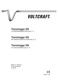
Setting up the "ThermoLog" program:
- Please close all Windows applications before setting up the program "Thermo-Log".
- Insert the set-up disk into the drive.
- Click on "Start" and select "Execute ..." from the task bar.
- Enter "A:\setup" and confirm with "OK". Now, the program and the help files will now be copied onto the hard disk. (the default directory is c:\programme\thermolog).
- Please follow the instructions on the screen for the set-up program.
To obtain further information, please use the online-help of the "ThermoLog" program.
Measuring procedure, Data transmission
Data transmission
A) General
We are (still) in the Main Menu. In this window, another small window appears, showing the text: "Cannot find any thermometer".
This message appears if the connected thermometer is switched off.
Switch on thermometer and click the "RETRY" item. If the message does not change, there is a problem - either as regards the thermometer (battery ?) or the connecting cable (perfect fit?) or the software installation (setup fault ?). Start anew and try everything again.
The following message appears if the connection was established successfully (depending on the computer):
"Serial Port : COM1
Model: Two Channel, K type thermometer"
Click "OK" to close the window.
In the "Main Menu" window, you can click wherever the mouse pointer is transformed into a hand with forefinger:
The item "Graph" ("Real Time"), a graphic representation of the real time measurement or
the "Control Panel" item, a representation of the operator panel of the thermometer with display or
the "Tabular" item, a tabular progressive representation of the temperatures T1 and T2, also in real time or
the item on the left center with tabular representation "Tabular", "Graph" and "Control Panel" in a window or
the "Data Logger" item, transfer of the saved data from the thermometer to the PC or
the "Link Test" item, a test of the connection between the computer and the digital thermometer or
the "Help" item, the so-called help file with menu guidance in German, but help texts in English or
last but not least the "Exit" item to exit the program.
B) Graph
Click the "graph" item. If you have a colour display or a colour monitor, you will see two continuously writing lines which represent the temperatures T1 (in yellow) and T2 (in red) as a function of the time T (time-of-day). Below, please find a brief description of the various commands:
Sampling Rate
Here you can set the scanning speeds, i.e. how fast / frequently the screen is to be refreshed. The maximum setting time is 59 minutes and 59 seconds. The shortest setting is 2 sec., i.e. a new screen appears at intervals of 2 seconds (new measured values).
? = Help
The item showing the question mark "?" is tantamount to the "Help" function in which the various field commands are explained.
Main Menu
By clicking this item, you get into the main menu.
Range
By clicking this item, you can define the range of temperature representation, e.g. from -20^ to +60^ or -50^ to +200^ . The unit depends on the thermometer setting; the bigger the setting range, the less precise the representation will be.
Option
By clicking this item, you get into another window labelled "Customization", which means "Adjustment". Using this item and the commands it contains, you can generate a heading and a remark (main and sub-title) in the various fonts, or change the background colours, or remove the grid lines, etc.
By clicking this item and by subsequently clicking the smaller item "Print", you issue the command for printing the screens.
"Eraser" Icon
By clicking the icon next to the printer icon, you return the graph to the start.
"11"
By clicking the item next to the question mark, you can stop the current representation (= pause). " > "
By clicking the item >^ , you continue current representation.
To close the "Graph" window, you have to click "x" on top right.
C) Control Panel
Click the item "Control Panel". Subsequently, the front side of your thermometer 306 with changing indication is displayed. Now you can operate your thermometer within certain limits from the PC using the mouse (not the setup data).
To close the "Control Panel" window, you have to click "x" on the top right.
D) Tabular
Click the "Tabular" item. Subsequently, you can see the continuous tabular representation of the measured temperature values from T1 and T2 in real time. Below, please find a brief description of the various commands:
Sampling Rate
Here you can set the scanning speeds, i.e. how fast / frequently the screen is to be refreshed. The maximum setting time is 59 minutes and 59 seconds. The shortest setting is 2 sec., i.e. a new screen appears at intervals of 2 seconds (new measured values, refer to bottom line).
? = Help
The item showing the question mark "?" is tantamount to the "Help" function in which the various field commands are explained.
Main Menu
By clicking this item, you get into the main menu.
Output to Graph or icon next to the question mark
By clicking this item, the temperature values are displayed graphically in another window.
"
By clicking the item next to the question mark, you can stop the current representation (= pause).
n > n ,Run
By clicking the item >'' or "Run", you continue current representation.
"Eraser"-Icon
By clicking the icon next to the printer icon, you return the graph to the start.
Printer icon = Print
By clicking the printer icon, you issue the command to print the screen.
File or icons for folder and diskette
By clicking "file", another small window unfolds: "New" means "new folder" (create);
"Open" means: open an existing folder; "Save" means: save the contents of the table in the current folder; "Save As" means: save contents of table in another folder (=save under); "Print" means: Print table.
To close the "Tabular" window, you have to click "x" on the top right.
E) Item in the left center
Clicking this window icon causes the windows "Tabular", "Control Panel" and "Graph" to appear once in a single window (overlapping).
F) Data Logger
Clicking this window icon causes a mix of "Tabular", "Graph", a "MAX MIN" representation and "Data Sets" (data records) to appear. Normally, the window is empty. To fill it with data, click the item "Load Data" once (appropriate icon offset to the right, below). Subsequently, the saved data of the measuring device are transferred
to the PC. On the bottom left, you see the maximum (MAX) and minimum value (MIN) of T1 and the maximum (MAX) and minimum value (MIN) of T2. The transferred data records are listed in the item above. If you click one of them, it is represented immediately in the graph shown beside. In this graph, you can increase the view (=zoom) by actuating and keeping pressed the left mouse button and via the mouse pointer, and restore the preceding state by actuating "undo zoom". The table representation "Tabular" below has been described above in sufficient detail. The various icons mean:
? = Help
The item showing the question mark "?" is tantamount to the "Help" function in which the various field commands are explained.
Main Menu
By clicking this item, you get into the main menu.
Maximize
By clicking this icon, the graphic window is opened to screen size. Subsequently, the window can be returned to its initial size by clicking the same item (now: Minimize).
Printer icon = Print
By clicking the printer icon, you issue the command to print the screen.
File or icons for folder and diskette
By clicking "file", another small window unfolds: "Open" means: open an existing folder; "Save" means: save the contents of the table in the current folder; "Save As" means: save contents of table in another folder (=save under); "Print Tabular" means:
Print table; "Print Graph" means: Print graphic (representation) and "Exit" means "Quit" or "close window" (tantamount to "x" on top right).
G) Link Test
Clicking this central window icon causes the connection between the connected thermometer and the PC to be checked. A smaller window showing the moving text "SEARCHING" appears briefly above the four buttons "OK", "CANCEL", "RETRY" and "HELP". In this context, please refer also to the description under "A) General". If the search is successful, the corresponding message will appear briefly afterwards. Click the button "OK" to close the window "Link Test".
H) HELP
By clicking this item (question mark above a book), you get to the help menu described above.
I) Exit
By clicking this icon (arrow to the right top side), you exit the ThermoLog window and terminate the program.
Note!
If the "ThermoLog" menu is activated, the corresponding icon also appears as so-called "Tray Icon" on the bottom right side in the "Windows" window, to the right of the loudspeaker symbol.
How to perform a measurement
The temperature measurement range of the digital thermometer ranges from -200^ to +1370^ .
The temperature range of the enclosed sensor ranges from -50^ to max.! 200^ . Do not use the probe delivered with the equipment to measure any temperatures greater than +200^ ( =392^ ).
It must be taken account of the fact that "outside" of the temperature range from +18^ to +28^ (=range of guaranteed measuring accuracy) only the thermo probe may be exposed to the temperature to be measured.
For temperature measurement, proceed as follows:
- Connect either one or two of the enclosed temperature sensors to the thermometer, as required for your purposes, and switch it on.

Do not connect voltages! This might destroy the device.
- Hold the temperature sensor(s) (line end(s)) to/in the de-energized measuring fluid (heat sink, etc., but not in caustic or inflammable fluids!).
Notes!
In the small display on the left, the differential temperature of T1 minus (-) the T2 temperature is continuously determined and indicated.
In the small display on the right, the temperature of T2 appears permanently. If one of the temperature sensors is not connected, or even interrupted, "- - - " appears instead of a measured value. In this case, difference determination is not performed / displayed either.
Disposal
If the digital thermometer 306 is not operable or defective beyond repair in spite of correct supply (9 V block battery), it must be disposed of according to the applicable legal requirements.
Troubleshooting
By purchasing the digital thermometer 306, you now have a product designed according to the state of the art.
Nevertheless, problems or trouble are not excluded. Thus, the following text describes the methods you can use to eliminate some of this trouble on your own; please make sure to observe the safety provisions!
| Errors Possible cause | |
| no transmission Safe contact of connection line? to PC Software loaded according to instructions? PC interface OK? | |
| No indication when Is the battery discharged? Did the measuring device switch off automatically after being out of operation for 30 minutes? | |
Maintenance and calibration
You should calibrate the thermometer annually in order to ensure the accuracy of the thermometers for a long period of time.
The adjustable capacitor "CAL" can be used to calibrate the measuring device. Use a Philip's screwdriver of a suitable size. Turn it carefully to the left and to the right during the measurement, until the display shows the exact value of the reference device.
The battery exchange is described under "Handling, commissioning A".
Use a clean, lint-free, antistatic and dry cleaning-cloth to clean the device and the display.

Do not use any carbon-based cleaning agents or gasolines, alcohols or similar fluids for cleaning. These might attack the surface of the unit. Moreover, the vapours are unhealthy and explosive. Do not use any sharp-edged tools, screw-drivers or metal brushes etc. for cleaning either.
Technical data and measuring tolerances Technical data
Display : 4-digit display up to 9999 with two smaller four-digit subdisplays, symbol displays and units
Max. measurement rate. . . . :1.25 measurements per second,
i.e. 5 measurements within 4 seconds
Working temperature
(Environment of measuring device) .: 0^ to +50^ (32°F to 122°F)
Storage temperature. -10^ to +60^ (14°F to 140°F),
battery removed)
Relative humidity . . . . . . . . . . . . . . . . . . . . . . . . . . . . . . . . . . . . . . . . . . . . . . . . . . . . . . . . . . . . . . . . . . . . . . . . . . . .. 0 to 80 %, not condensing
Temperature for
guaranteed accuracy. +23^ ± 5K
Temperature coefficient . . . . . . . . . . . . . . . . . . . . . . . . . . . . . . . . . . . . . . . . . . . . . . . . . . . . . in addition 0.01% of reading +0.03^
(or 0.01% of reading +0.06^) per K in the
range from 0^ to 18^
and from 28^ to 50^
Battery replacement indicator . . . . . : , at less than approx. 7.3 V
battery voltage
Battery type :NEDA 1604 9V or 6F22 9V (alkaline)
Weight. :210 g (with battery)
Dimensions (L× W× H). 184 x 64 x 30 mm (without cables)
Measuring tolerances
Accuracy specified in + (% of reading + indication error in Kelvin "K") "K" for Kelvin is used as the absolute value of a differential temperature or temperature deviation.
Accuracy for 1 year at a temperature of +23^ ± 5K , at a relative humidity of less than 80% , non-condensing. The warm-up time is 1 minute
| Measuring range Accuracy Resolution | |
| Measuring device: -200°C bis +200°C ±(0,2%+1°C) 0,1°C +200°C bis +400°C ±(0,5%+1°C) 1°C +400°C bis +1370°C ±(0,2%+1°C) 1°C -328°F bis -200°F ±(0,5%+2°F) 0,1°F -200°F bis +200°F ±(0,5%+2°F) 0,1°F +200°F bis +2498°F ±(0,5%+2°F) 1°F |
Temperature sensor TP-K01
-50°C to +200°C
± 2.2K or ± 0.75%
-58°F to +392°F
± 3.6K or ± 0.75%

If the max. admissible input quantities are exceeded, this might under adverse circumstances damage the measuring device, or endanger the user's life.
F Introduction
Cher Client,
Model: Two Channel, K type thermometer"
Printersymbol = Print