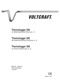
UM51 200 - Thermometer VOLTCRAFT - Free user manual and instructions
Find the device manual for free UM51 200 VOLTCRAFT in PDF.
Document temporarily unavailable
The manual is currently being transferred to our new server. It will be accessible again in a few hours. Thank you for your patience.
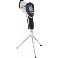
| Product type | Environmental measurement instrument (anemometer, luxmeter, sound level meter, thermometer, hygrometer) |
| Weight | 282 g (instrument without accessories) |
| Power supply | 1 x 9 V battery |
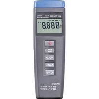
| Display | Large LCD screen with backlight |
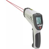
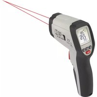
| Measurement functions | Sound level, light intensity, wind speed, air temperature, type K temperature, relative humidity |
| Measurement ranges | Sound: 30-130 dBA; Light: 0-20000 Lux; Wind: 0.4-30 m/s; Air temp.: -30 to +60°C; Type K temp.: -200 to +1372°C; Humidity: 0-100% RH |
| Interface | USB (USB-UART bridge) |
| Intended use | Indoor comparative measurements (factories, schools, offices, home). Not for medical or outdoor use. |
| Safety | Avoid humidity, extreme temperatures, shocks. Do not use in explosive atmosphere. Observe battery polarity. |
| Maintenance | Clean with a dry, lint-free cloth. No aggressive products. |
| Included parts | Probes (temperature/humidity, type K, anemometer, light), tripod, USB cable, software CD, carrying case, 9 V battery |
| Repairability | Repairs by qualified technician only. No spare parts listed. |
| Configuration options | Changeable units (°C/°F, Lux/FC, dBA/dBC, m/s/ft/min, etc.), adjustable auto power off, temperature offset. |
| Additional functions | HOLD, MIN/MAX/AVG recording, backlight, disableable auto power off. |
Frequently Asked Questions - UM51 200 VOLTCRAFT
User questions about UM51 200 VOLTCRAFT
0 question about this device. Answer the ones you know or ask your own.
Ask a new question about this device
Download the instructions for your Thermometer in PDF format for free! Find your manual UM51 200 - VOLTCRAFT and take your electronic device back in hand. On this page are published all the documents necessary for the use of your device. UM51 200 by VOLTCRAFT.