FUSG50110 - Alarm system ABUS - Free user manual and instructions
Find the device manual for free FUSG50110 ABUS in PDF.

| Product type | Wireless indoor siren for Secvest alarm system |
| Brand | ABUS |
| Model | FUSG50110 |
| Category | Alarm system |
| Dimensions (W x H x D) | 130 x 154 x 40 mm |
| Weight (without batteries) | 218 g |
| Weight (with batteries) | 310 g |
| Main power supply | External 12 V DC (via power supply) or 4 AA alkaline batteries (6 V) |
| Battery type | 4 x AA alkaline (Duracell Procell MN1500, Duracell Industrial ID1500, Energizer E91) |
| Battery life | More than 12 months (with 2500 mAh, 80 s of tones per day) |
| Sound pressure level | > 80 dB(A) at 1 m |
| Radio frequency | 868.6625 MHz (low data rate) |
| Radio range (open field) | Up to 500 m |
| Security grade | 2 (according to EN 50131) |
| Protection rating | IP30 (indoor, mounted) |
| Operating temperature | -10 °C to +40 °C |
| Main functions | Piezo siren, 3 status LEDs, tamper contact (housing and wall), jamming detection, voltage monitoring, mute after 3 min on battery |
| Displays | 3 LEDs (red, yellow, green) for software version and signal strength |
| Compatibility | Secvest alarm control panels FUAA50xxx (from v3.01.11) and repeater FUMO50010 |
| Maintenance and cleaning | Clean with a soft, dry cloth. Do not use water, solvents or cleaning agents. Replace batteries every 2 years or if low battery indication appears. |
| Safety | Tamper protection (housing and wall), error monitoring, jamming detection, installer mode for maintenance |
| Spare parts and repairability | Batteries are replaceable by the user. No other spare parts provided. In case of defect, contact the dealer. |
| General information | Installation and user manual available as PDF. 2-year warranty. Compliant with European directives (RED, EMC, RoHS, WEEE, ErP, Low Voltage). |
Frequently Asked Questions - FUSG50110 ABUS
User questions about FUSG50110 ABUS
0 question about this device. Answer the ones you know or ask your own.
Ask a new question about this device
Download the instructions for your Alarm system in PDF format for free! Find your manual FUSG50110 - ABUS and take your electronic device back in hand. On this page are published all the documents necessary for the use of your device. FUSG50110 by ABUS.
USER MANUAL FUSG50110 ABUS
Installation instructions and user manual
FR
Installation instructions and user guide
FR
Information on user guide 31
Intended use 31
Limitation of liability 32
Safety information 33
Explanation of symbols 33
Packaging 33
Information on the battery 34
Scope of delivery 34
Technical data 35
Functional principle and features 39
General 39
Main features 39
Device description. 40
Compatible equipment 40
Installation 41
Step 1: Select installation location for the sounder 41
Step 2: Open the cover of the sounder 41
Step 3: Mount the sounder on the wall 42
Step 4: Switch on the sounder and start operation. 43
Step 4a: Power supply 44
Step 4b: Pair the sounder with the alarm panel. 45
Step 4c: Close the housing 46
Step 5: Test the system 46
Functions and displays 48
Software version displayed by LEDs 48
Battery status displayed by LEDs 48
Signal strength displayed by LEDs 49
Acoustic signal tones 50
Volume of the signal tones. 51
Switch-off time of the signal tones 51
Error and tamper monitoring 51
Time conditions 52
Factory Defaults 52
Maintenance 53
Maintenance by the user 54
Warranty 55
Customer service and support 55
Decommissioning the indoor sounder 56
Disposal 56
Declaration of conformity 56
Introduction
Information on user guide
Dear customer,
Thank you for purchasing this product. This device is a product that has been built using state-of-the-art technology.
These instructions contain important installation and operation information. Follow the directions and instructions in this user manual to ensure safe operation. Store this manual in a safe place for future reference. This manual constitutes part of the device. If you pass the device on to third parties, please remember to include this manual.

Note
S/W 1.8
This manual relates to software version 1.8 of the sounder and all other previously published software versions. All new features that are only valid from a certain software version are marked accordingly, e.g. >=1.1 . All other features that are valid up to a certain software version are also marked accordingly, e.g. <1.1 . This manual relates to the software version >= v3.01.14 of the Secvest alarm panel.
Intended use
Only use the device for the purpose for which it was built and designed. Any other use is considered unintended. This product complies with current domestic and European regulations. The wireless indoor sounder is supported from Secvest software version v3.01.11.
Conformity has been certified, and all related certifications are available from the manufacturer on request.
To ensure this condition is maintained and that safe operation is guaranteed, it is your obligation as the user to observe this user guide. If you have any questions, please contact your specialist dealer. Further general information and information on product support can be found at www.abus.com on the general page or for dealers and installers, in the Partner portal.
| Note | Please observe the notes and instructions in this user manual! If you do not follow these instructions, any guarantee claim is invalidated. No liability can be accepted for resulting damage. No part of the product may be changed or modified in any way. Please observe the local legal requirements for the use of acoustic sounders. In some European countries, the use of sounders is locally restricted or the maximum alarm duration is limited. Please consult your local authorities on this. |
| Danger | Set the alarm panel to installer mode before starting any installation or maintenance work. Installer mode prevents alarms from being activated when the sounder's cover is opened. |
Limitation of liability
Everything possible has been done to ensure that the content of these instructions is correct. However, neither the author nor ABUS Security-Center GmbH & Co. KG can be held liable for loss or damage caused by incorrect or improper installation and operation or failure to observe the safety instructions and warnings. No liability can be accepted for resulting damage. No part of the product may be changed or modified in any way. If you do not follow these instructions, your warranty claim becomes invalid. Subject to technical modifications.
© ABUS Security-Center GmbH & Co. KG, 10/2019
Safety information
Explanation of symbols
The following symbols are used in this manual and on the device:
| Symbol | Signal word | Meaning |
| ! | Danger | Indicates a risk of injury or health hazards. |
| Danger | Indicates a risk of injury or health hazards caused by electrical voltage. | |
| Important | Indicates possible damage to the device/accessories. | |
| i | Note | Indicates important information. |
| The EU Directive WEEE 2012/19/EU governs the proper recovery, treatment and recycling of used electronic devices. This symbol means that, in the interest of environmental protection, the device must be disposed of separately from household or industrial waste at the end of its lifespan in accordance with applicable local legal guidelines. Used devices can be disposed of at official recycling centres in your country. Obey local regulations when disposing of materials. Further details on returns (also for non-EU countries) can be obtained from your local authority. Separate collection and recycling conserve natural resources and ensure that all the provisions for protecting health and the environment are observed when recycling the product. |
Packaging

Danger
Keep packaging material and small parts away from children.
There is a risk of suffocation!
Remove all packaging material before using the device.
Information on the battery
| Danger Danger | The device is supplied with direct current from batteries. To guarantee a long lifespan and avoid fire and injury, please note the following: ·Do not dispose of the battery with household waste. ·The battery must not be directly exposed to heat or sunlight, and must not be stored in hot places. ·The battery must not be burned. ·The battery must not come into contact with water. ·The battery must not be dismantled, pierced or otherwise damaged. ·The battery contacts must not be short-circuited. ·The battery must be kept out of reach of small children. ·The battery cannot be recharged. |
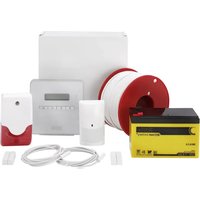
Scope of delivery
- 1x Secvest wireless indoor sounder
- 4x batteries, type AA
- Quick guide and safety instructions
- Installation material
Technical data
| Environmental class | II (EN 50131-1 + A1:2009 + A2:2017 Section 7, EN 50131-3:2009 Section 7) | |
| Protection class, IP protection class | IP30 (internal spaces, in its installed state) IP = international protection or ingress protection 3 = Protection from foreign objects: protected against solid foreign objects with a diameter of > 2.5 mm, Protection from contact: protected against access with a tool and wires Ø >2.5 mm 0 = Protection from water: no protection | |
| Operating temperature | -10 °C to 40 °C | |
| Storage temperature | -10 °C to 40 °C | |
| Humidity, maximum | non-condensing average relative humidity approx. 75% | |
| Housing material | PC/ABS | |
| Dimensions (W x H x D) | 130 x 154 x 40 mm | |
| Weight | 218 g (without batteries) 310 g with batteries 4 x approx. 23 g (92 g) batteries alone | |
| Security level | Level 2 (EN 50131-1 + A1:2009 + A2:2017 Section 6, EN 50131-3:2009 Section 6) | |
| Tamper protection (detection/protection) | Type B (EN 50131-3:2009 Section 8.7) | |
| Signal generation | Integrated piezo sounder | |
| Sound pressure level | >80 dB(A) @ 1 m User Menu -> System Config -> Volume Settings Alarm Sounds = 10 | |
| Switch-off time | The device will be automatically muted after three minutes when in battery mode | |
| Displays | 3 status LEDs for software status and signal strength | |
| Connections | 12 V DC IN Screw terminal BATT1 and BATT2 2 battery compartments with space for 2 batteries each | |
| Power supply type | Type B (EN 50131-1:2006 + A1:2009 + A2:2017 Section 9 and EN 50131-6:2017 Section 4.2) for external power supply via power supply unit and batteries inserted as a backup power supply. Type C (EN 50131-1:2006 + A1:2009 + A2:2017 Section 9 and EN 50131-6:2017 Section 4.2) for pure battery operation without external power supply via power supply unit. Power supply compliant with EN 50131-1:2006 + A1:2009 + A2:2017 9.2 and EN 50131-6:2017 if installed correctly together with Secvest FUAA50xxx. | |
| Operating voltage | 6 – 15 V DC, 12 V nominal (external power supply unit) and 6 V DC (batteries) or 6 V DC (batteries), 4,4-6V DC | |
| Power consumption, maximum | I DC maximum: 100 mA @ 12 V DC Defined by: Piezo sounder on full volume | |
| Power consumption, maximum | ||
| Power consumption, nominal | Standby current 12 mA @ 12 VDC Defined by: RXTX on, Piezo sounder off | |
| Power consumption, typical | 0.144 W 0.144 W x 24 h x 365 = 1261 kWh per year Standby current 30 uA @ 6 V DC (batteries) Defined by: RXTX off, Piezo sounder off | |
| Battery type | 4 x AA alkaline batteriesDuracell Procell MN1500, Duracell Industrial ID1500,Energizer E91 | |
| Battery life | more than 12 months with AA cells @ 2500 mAhwith pure battery operation and a total of 80 s input/output tones per day | |
| Standby time of the energy storage system | Type W (EN 50131-4:2009 Section 5.6.3.2) for battery operation only, without external power supply via power supply unit.Type X (EN 50131-4:2009 Section 5.6.3.2) external power supply via power supply unit and batteries inserted as a backup power supply. | |
| Lower threshold value of the batteries | 4.8 V"Flat battery" fault at < 4.8 V4.4 VCut-off voltage | |
| Voltage monitoring | During battery operation without any external power supply, only the voltage provided by the batteries is monitored. If the voltage is below the lower threshold of 4.8 V, a fault report is sent to the alarm control panel and the user is informed. The external power supply is not monitored in this mode.During operation with an external power supply, a fault report is sent to the alarm control panel as soon as the external power supply is interrupted. The indoor sounder then automatically continues to be powered by the batteries. The corresponding notification on the alarm control panel informs the user about this. The batteries can be monitored as described above. | |
| Operating frequency | 868.6625 MHz narrow band | |
| Wireless power output | max. 10 mW | |
| Transmission and reception range | max. 500 m range outdoors | |
| Wireless identification | Wireless components, differentiation16,777,214 (224 -2) different IDs | |
| Standards for intrusion and panic button devices | Complies with EN 50131-1:2006+A1:2009+A2:2017, EN 50131-3:200 EN 50131-4:2009, EN 50131-5-3:2005+A1:2008 and EN 50131-6:2017 security level 2 if installed correctly together with the Secvest FUAA50xxx. | |
| EU Directives | RED | 2014/53/EU |
| EMC | 2014/30/EU | |
| RoHS | 2011/65/EU | |
| WEEE | 2012/19/EU | |
| ErP | 2009/125/EU | |
| Low voltage | 2014/35/EU | |
| General safety | 2001/95/EG | |
| General | This product must be installed, serviced and maintained by a qualified service engineer. External cleaning work can be carried out by the user. | |
Functional principle and features
General
The indoor sounder is an additional component for use with Secvest alarm panel FUAA50xxx. It serves to signal alarm sounds, information sounds and operating sounds.
The indoor sounder can be powered by an external power supply and with batteries to bridge power failures.
The indoor sounder can also be operated with batteries only.
It is designed for wall installation.
Main features
| Simple installation | Hinged lid for easy installation |
| Shock-resistant construction from polycarbonate | Housing and wall tamper contact |
| Four per alarm panel | Monitors the input voltage |
| 500 m range outdoors | Power supply unit operation or battery operation |
| Repeatable | Jamming detection |
Device description
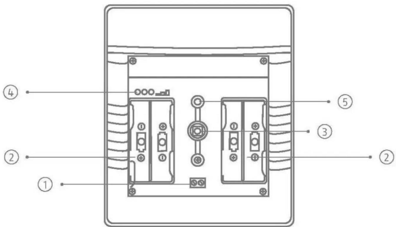
Image 1
| 1 | Connection for power supply |
| 2 | Battery compartments |
| 3 | Tamper switch |
| 4 | LEDs red, yellow, green |
| 5 | Piezo element (situated on the back, not visible) |
Compatible equipment
- FUAA50xxx Secvest alarm panels from software v3.01.11
FUMO50010 wireless repeater
Installation
Step 1: Select installation location for the sounder
Select an installation location within the wireless range of the alarm panel (max. 500 m outdoors). Make sure the external power supply unit has a suitable 230 V power supply.

Note
Before starting installation, identify a suitable installation location for the sounder if necessary using the wireless test box.
Incorrect or unclean installation work may lead to erroneous interpretation of signals, the consequences of which may include false alarms. The costs incurred by potential dispatches of rescue services, such as the fire service or police, must be borne by the operator of the system.
To ensure trouble-free operation, the sounder must NOT be installed:
- at a distance of less than 1m from large metal structures such as metal doors or frames, water tanks, refrigerators or vehicles
- at a distance of less than 1m from household electrical systems, distributors or metal pipes
- inside metal housings
- close to the main power supply, or close to water or gas pipelines
- close to high-voltage devices or electronic devices such as computers, photocopiers or other wireless devices
Step 2: Open the cover of the sounder
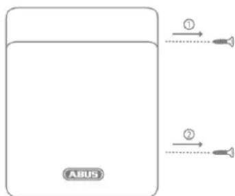
Image 2
- Open the two covers of the two cover fixing screws.
- Remove the two screws and open the cover (Image 2)
Step 3: Mount the sounder on the wall
| i Note | The sounder is protected against unauthorised opening and wall tampering contact via the housing tamper switch and the wall tamper switch. The tamper information is transmitted to the alarm panel. |
| i Note | A moulded piece in the recess of the backplate (Point 4 Image 3) serves as an anti-removal wall contact. This moulded piece is fixed to the wall with a screw. If this is not done, tamper detection for the wall is deactivated. |
| Danger | If the moulded part is not mounted to the wall, the sounder will lose its certification for security level 2. The sounder was designed so that changes are detected if they last at least 400 ms (EN50131-1 Chapter 8.9.1 and EN50131-3 Chapter 8.9 and Annex B). Breaking and entering, intrusion and tampering signals must last at least 400 ms. |
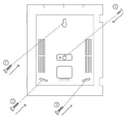
Image 3
- Place the sounder on the wall and align it vertically. Use the base plate as a drilling template and mark the four fixing points.
- Drill the holes in the wall to fit the diameter of the screw anchors. Insert the screw anchors supplied, in the holes.
- Insert the supplied screws through the sounder's fixing holes. Turn the screws in the screw anchors. Do not tighten the screws yet. Vertically align the sounder once more. Now tighten the screws.
Step 4: Switch on the sounder and start operation
| Danger | The sounder works with SELV – Safety Extra Low Voltage. SELV < 25 V AC or < 60 V DC |
| These voltages do not pose a threat to animals or children. | |
| If the nominal voltage is below 25 V for alternating current or below 60 V for direct current, then there is no need for protection against direct contact with SELV. The typical alarm system connections are designed for Safety Extra Low Voltage (SELV). The 12 V power supply of the ABUS alarm panels and other components also operate in this voltage range. | |
| Important | Observe the permissible voltage range and the maximum current output of the PSU. |
| Important | For a security system, tamper-proof wiring/tamper monitoring of the wiring between the components is also important and required. |
| Important | Place the cables in such a way that none are crushed. |
Step 4a: Power supply
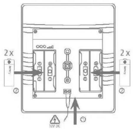
Image 4
- Establish the power supply. Either with 4 × 1.5V batteries or batteries and a power supply unit. Make sure the batteries and power supply unit cables are connected with the correct polarity.
- Remove the isolation divider from any inserted batteries.
- Then insert the power supply unit into the socket.
| Danger | If connected to an external power supply, the sounder must also always be operated with batteries. The sounder will then continue using the batteries as a backup power supply in the event of a power failure. |
| Note | If the red and yellow LEDs flash alternately immediately after displaying the software version, this indicates a battery power supply fault. • No batteries have been inserted • Or the batteries have a voltage < 4,4 V (normal batter voltage is 6 V) |
| i Note | The power supply connection determines the sounder's operating mode. |
| i Important | Operating modes: Power supply unit operation or battery operation The sounder detects the power supply unit or battery operation immediately when it is switched on. • If the sounder is switched on without an external power supply unit, it is in battery operation mode and does not report an external PSU fault. If the power supply unit is added later, the sounder remains in battery operation mode. • If the sounder is switched on with an external power supply unit, it is in PSU mode. If the power supply unit is removed later or it supplies no voltage due to a malfunction, a PSU fault is reported and signalled to the alarm panel. |
| Important | In battery operation mode, the sounder is automatically muted after 3 minutes. In addition, battery-saving functions are enabled. |
| i Note | The software version of the sounder is indicated by the LEDs immediately after the power supply is connected. You can find details on this in the chapter "Software version displayed by LEDs". |
| i Important | Insert the cables into the guides provided. Otherwise, the cables may be crushed. |
Step 4b: Pair the sounder with the alarm panel
- If this has not been done already, start operation of the alarm panel.
- Select:
Installer mode -> Components -> Indoor sounder > Add/remove > Indoor sounder 0x
- Select the desired position. Indoor sounder 01 to indoor sounder 04
- You will receive the message "Activate the tamper contact of the indoor sounder". Flick the tampering switch.
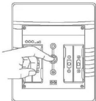
Image 5
- The sounder will then send a pairing signal to the alarm panel. The alarm panel will recognise the sounder. Once the pairing signal has been received by the wireless alarm system, it will emit two beeps. The notification "Indoor sounder added" and the incoming signal strength will be displayed.
- Confirm the successfully completed pairing on the alarm panel.
- On the alarm panel, you can go to Installer Mode -> Components -> Indoor sounder -> Edit -> to determine which partitions the indoor sounder should report on. You can also assign an individual name here.
- You can find descriptions for all further programming in the corresponding chapters of the Secvest installer manual.
Step 4c: Close the housing
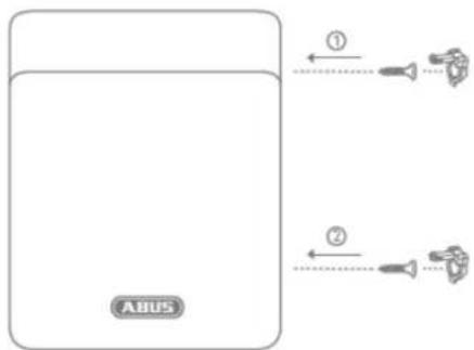
Image 6
- Close the cover, tighten the cover fixing screws and close the covers of the screws.
Step 5: Test the system
General:
Test the system fully.
- Check that all connected components function properly.
- Check that the system as a whole responds properly to the connected components.
- Check if the correct notifications are shown on the alarm panel and if the corresponding reactions are triggered.

Note
You can also test the system when the sounder is open. However, do not leave Secvest installer mode to do so.
Signal strength
- Signal strength of the indoor sounder on the alarm panel
Installer mode > Test > Signal strengths -> Indoor sounder
Here you can see the signal strengths of the paired indoor sounder.
Piezo sounder
WBI:
Installer mode > Test > Int. sounders
Alarm panel:
Installer mode > Test > Sounders & signallers -> Int. sounders

Note
It sends a "test tone" to all available indoor sounders (indoor sounder, info module, control panel, loudspeaker of the hybrid module). All these components are activated at the same time.

Note
You can set the volume of the different signal tones in the user menu.
User menu -> Configuration -> Volume settings ->
Operator Sounds
Info tones:
Alarm tones:
Housing and wall tamper switches
- Check that the switch functions properly.
- Exit installer mode on the alarm panel to do this.

Danger
Note that after exiting the installer mode, the alarm panel will execute the programmed alarm responses to tampering.

Danger
Inform the communication recipient about the test to be carried out to prevent fault responses, or deactivate communication for this test.

Danger
Make sure that any loud sounds emitted by sounders belonging to this system do not startle you (e.g. causing you to fall off a ladder) or cause an annoyance.
- Open and close the tamper switch.
- Check if the correct notifications are shown on the alarm panel and if the corresponding alarm reactions are triggered.
Functions and displays
Software version displayed by LEDs
The software version of the sounder is indicated by the LEDs immediately after the power supply is connected.

The tamper switch must be open.
- The red left-hand LED indicates the major software version.
- The green right-hand LED then indicates the minor software version
- The yellow LED in the middle then indicates the variant.
Example: Red left LED flashes once
Green right LED flashes eight times
Yellow middle LED flashes four times Software version "1.08.04"
Battery status displayed by LEDs
If the red and yellow LEDs flash alternately immediately after displaying the software version, this indicates a battery power supply fault.
- No batteries have been inserted
- Or the batteries have a voltage < 4,4V (normal batter voltage is 6V )

To restart, remove the power supply and insert good-quality batteries (>4,4V)
The sounder will not be restarted without completely shutting down.
Signal strength displayed by LEDs
When operational, the received signal strength is tested by a message sent from the alarm panel. To do this, switch "Installer mode -> Test -> Sounders & Signallers -> Indoor sounders" on and off. The tamper switch must be open.
Red: poor signal strength
Red and yellow: medium signal strength
Red, yellow and green: good signal strength

Note
Set the alarm panel to installer mode in order to test the signal strength while operational. This ensures that a tamper alarm is not triggered when the sounder is opened.
You can find notes about testing the signal strength on the alarm panel on the alarm panel's installer manual.
Acoustic signal tones
The sounder is able to generate a wide range of acoustic signal tones. These are similar to the alarm tones, information tones and operating tones of the wireless alarm panel.
The following table shows an overview of the signal tones and their group assignment.
| Signal tones | Meaning |
| Alarm tones: | Breaking and entering/intrusionFireMedical alarmEmergency call |
| Medical alarmEmergency call | |
| ChimeExit toneE.g.:Long continuous beep (beeeeeeeeeeep):During the exit delay time. All zones closed, the alarm panel is activated after the delay time has expired. | |
| Exit tone in the event of a faultE.g.:Interrupted beeps (beep...beep...beep):A zone was opened during the exit delay time. It must be closed before the delay time expires. | |
| Entry toneE.g.:Interrupted beeps (beep...beep...beep):During the entry delay time. | |
| Operator Sounds | Acknowledgement/confirmationE.g.:Double deep (beep, beep):The alarm panel has been successfully activated. |
| ErrorE.g.:Short beep (beep):System fault, the alarm panel cannot be activated |

Note
When the sounder is being operated through batteries only, it eliminates the playback of information and operating tones.
During operation with a power supply unit, alarm, information and operating tones are signalled.
Volume of the signal tones
The volume of the signal tones can be configured separately for each group.
User menu -> Configuration -> Volume Settings
Operator Sounds 0-10
Info Sounds 0-10
Alarm Sounds 0-10

Note
The required volume according to EN50131-4 (Alarm systems - Intrusion and hold-up systems - Part 4: Warning devices) for security grade 2 of >80 dB (A) @ 1m is given when setting the Alarm Sounds = 10.

Note
These volume settings affect the volume of the alarm panel and the indoor sounder.

Note
The maximum volume on the sounder is limited when the batteries are empty.
Switch-off time of the signal tones
In battery operation mode, the sounder is automatically muted after 3 minutes.
Error and tamper monitoring
The sounder continually monitors error and tamper states and reports all events to the alarm panel. The following is monitored:
- Tamper contact: The sounder's tamper contact is continually monitored.
- Supply voltage and battery voltage: The sounder monitors the supply voltage and battery voltage under load conditions and reports all faults to the alarm panel.
- Supervision
- The indoor sounder continually sends supervision messages to the alarm panel
- Signal jamming: The indoor sounder monitors attempts to jam the wireless signal. If jamming is detected, the message "Signal jamming" is sent to the alarm panel.

Danger
The sounder was designed so that changes are detected if they last at least 400 ms (EN50131-1 Chapter 8.9.1 and EN50131-3 Chapter 8.9 and Annex B).
Breaking and entering, intrusion and tampering signals must last at least 400 ms.
The sounder was designed so that changes to the fault status (fault signals) are detected if they last at least 10 s (EN50131-1 Chapter 8.9.1 and EN50131-3 Chapter 8.9 and Annex B).
Time conditions
The sounder was designed so that changes are detected if they last at least 400 ms (EN50131-1 Chapter 8.9.1 and EN50131-3 Chapter 8.9 and Annex B). Breaking and entering, intrusion and tampering signals must last at least 400 ms.
The sounder was designed so that changes to the fault status (fault signals) are detected if they last at least 10 s (EN50131-1 Chapter 8.9.1 and EN50131-3 Chapter 8.9 and Annex B).
Factory Defaults
If the sounder is taught-in to the alarm panel again, it discards all previous links. This causes the sounder to return to the factory default.
Maintenance

Danger
Before opening the indoor sounder cover, make sure that the alarm panel is in installer mode. This prevents the tamper alarm from being triggered.
Test, during routine maintenance, that the indoor sounder works properly.
Check the tamper contacts.
Check for signs of insects having made their way in to the device and clean as required.

Danger

Note
The indoor sounder will not be restarted without completely shutting down.
The device must be disposed of in accordance with the WEEE Directive and applicable local and national regulations.
Replace the batteries every two years or if the alarm panel displays the message "Flat battery in indoor sounder". You can find the battery type to be used as a replacement under Technical data.

Note
After removing the old batteries, wait 30 seconds before inserting the new batteries.
How to replace the batteries:
- Put the alarm panel in installer mode.
- Open the covers for the lid-fixing screws (see Fig. 1), loosen the screws and open the lid.
- Disconnect the 12 V power supply
Take out the batteries. - Wait 30 seconds, then insert the new batteries.
- Reconnect the 12 V power supply
- Close the cover, tighten the cover fixing screws and close the covers of the screws.
Test the system.

Danger
The sounder will not be restarted without completely shutting down.

Note
Batteries and the device itself must be disposed of in accordance with the WEEE Directive and applicable local and national regulations.
The sounder should be checked once a year. During every inspection:
- Check the sounder for visible signs of damage on the housing or the front cover.
- Check the condition of the housing-tampering switch and the wall-tampering switch (wall-removal contact)
- Check the condition of the backup batteries
- Check the cabling for visible signs of damage or wear
-
Clean the sounder
-
When cleaning the surface, use a soft, dry cloth.
Do not use any water, solvents or cleaning agents. -
Check the signal strength
- Check the charging status of the batteries
- Replace the batteries when recommended by the manufacturer
Test the sounder
Test the communication. - EN 50131-7 "Alarm systems - intrusion and hold up alarms - part 7: application rules" must also be taken into consideration.
It is not necessary to check any calibrations or adjustments.
Maintenance by the user
Clean the sounder
- When cleaning the surface, use a soft, dry cloth.
o Do not use any water, solvents or cleaning agents.
- The user does not need to carry out any other maintenance work.
Warranty

Note
- ABUS products are designed and manufactured with the greatest care and tested according to the applicable regulations.
- The warranty only covers defects caused by material or manufacturing errors at the time of sale. If there are demonstrable material or manufacturing errors, the module will be repaired or replaced at the guarantor's discretion.
- In such cases, the warranty ends when the original warranty period of two years expires. All further claims are expressly rejected.
- ABUS will not be held liable for defects and damage caused by external influences (e.g. transport, use of force, operating errors), inappropriate use, normal wear and tear, or failure to observe the instructions in this manual.
- In the event of a warranty claim, the original receipt with the date of purchase and a short written description of the problem must be supplied with the product.
- If you discover a defect on your wireless indoor sounder which existed at the time of purchase, contact your dealer directly within the first two years following purchase.
Customer service and support
End consumer
Please consult your dealer or installer if you have any questions.
Dealer/installer
In case of questions, please contact the appropriate support hotline.
Consult our website for product information.
Decommissioning the indoor sounder
- Select:
Installer mode -> Components -> Indoor sounder > Add/remove > Indoor sounder 0x
- Select the desired sounder. Indoor sounder 01 or indoor sounder 02 or indoor sounder 03 or indoor sounder 04.
- You will receive the message "Remove indoor sounder?". Press "Select".
- Remove the sounder's power supply.
- Remove the installation and dismount the sounder.
Disposal
Dispose of the device in accordance with EU Directive 2012/19/EU – WEEE (Waste Electrical and Electronic Equipment). If you have any questions, please contact the municipal authority responsible for disposal. You can get information on collection points for waste equipment from your local authority, from local waste disposal companies or
your dealer, for example.
Dispose of the packaging material in accordance with local regulations.
Declaration of conformity
ABUS Security-Center hereby declares that the wireless system type FUSG50110 complies with RED Directive 2014/53/EU. The full EU Declaration of Conformity text can be found at: www.abus.com > Item search > FUSG50110 > Downloads
The Declaration of Conformity can also be obtained from the following address:
Installation instructions and user manual
FR
Chere cliente, cher client,
Installation instructions and user manual
FR
Installation instructions and user manual
FR
Installation instructions and user manual
FR