Harrison II - Stapler PRESIDENT - Free user manual and instructions
Find the device manual for free Harrison II PRESIDENT in PDF.

| Product type | CB Citizen Band transceiver |
| Brand | PRESIDENT |
| Model | Harrison II |
| Dimensions (L x W x H) | 125 x 165 x 45 mm |
| Weight | 0.571 kg |
| Power supply | 13.2 V or 26.4 V DC |
| Frequency range | 26.965 MHz to 27.405 MHz (40 channels) |
| Modulation modes | AM and FM |
| Antenna impedance | 50 ohms |
| Transmit power | 4 W AM / 4 W FM |
| Main functions | Squelch, ASC, VOX, Scan, Talkback, Roger Beep, ANL/NB/HI-CUT/NRC filters, CTCSS/DCS, Built-in SWR, Color display, Keypad lock, Relay |
| Microphone type | Electret or dynamic (6-pin) |
| Rear connectors | Power, SO-239 antenna, Micro VOX, PA speaker, External speaker |
| Protection | Reverse polarity protection, fuse |
| Transmit current consumption | < 2 A (13.2 V) / < 1 A (26.4 V) |
| Receive current consumption | 180 to 500 mA (13.2 V) / 90 to 250 mA (26.4 V) |
| Included accessories | Electret microphone with UP/DN keys, microphone holder, mounting bracket, screws, power cord with fuse |
| Maintenance | Clean with a soft, dry cloth. Do not use solvents. |
| Warranty | 2 years parts and labor in country of purchase (extendable to 5 years with President antenna) |
| Repairability | Spare parts available from President network (microphone, fuse, antenna, etc.) |
Frequently Asked Questions - Harrison II PRESIDENT
User questions about Harrison II PRESIDENT
0 question about this device. Answer the ones you know or ask your own.
Ask a new question about this device
Download the instructions for your Stapler in PDF format for free! Find your manual Harrison II - PRESIDENT and take your electronic device back in hand. On this page are published all the documents necessary for the use of your device. Harrison II by PRESIDENT.
USER MANUAL Harrison II PRESIDENT
FUNCTION WITH THE PTT SWITCH 45
MENU 45
TECHNICAL CHARACTERISTICS....50
TROUBLE SHOOTING....50
HOW TO TRANSMIT OR RECEIVE A MESSAGE 50
GLOSSARY 51
SIMPLIFIED EU DECLARATION OF CONFORMITY 52
GENERAL WARRANTY CONDITIONS....53
FREQUENCY TABLES....70 \~ 72
NORMS - F 74
SUMARIO
Español
INSTALACIÓN 22
UTILIZACIÓN 24
FUNCIONES AL ENCENDER LA EMISORA....28
natural_image
Six identical line drawings of a car viewed from top and side, showing different angles and orientations (no text or symbols)Lobe de Rayonnement
c) Antenne fixe
1) MARCHE/ARRÊT \~ VOLUME
PA (pression longue)
HI-CUT (pression longue)
12) PÉDALE D'ÉMISSION PTT (Push To Talk)
| A | Alpha | H | Hotel | O | Oscar | V | Victor |
| B | Bravo | I | India | P | Papa | W | Whiskey |
| C | Charlie | J | Juliet | Q | Quebec | X | X-ray |
| D | Delta | K | Kilo | R | Romeo | Y | Yankee |
| E | Echo | L | Lima | S | Sierra | Z | Zulu |
| F | Foxtrot | M | Mike | T | Tango | ||
| G | Golf | N | November | U | Uniform |
LANGUAGE TECHNIQUE
SW : Short waves (ondes courtes)
FB : Fine business (bon, excellent)
DÉCLARATION DE CONFORMITÉ UK SIMPLIFIÉE
natural_image
Six identical diagrams of a car with cross-sectional views, no text or symbols presentLóbulo de radiación
c) Antena fija
| A | Alpha | H | Hotel | O | Oscar | V | Victor |
| B | Bravo | I | India | P | Papa | W | Whiskey |
| C | Charlie | J | Juliet | Q | Quebec | X | X-ray |
| D | Delta | K | Kilo | R | Romeo | Y | Yankee |
| E | Echo | L | Lima | S | Sierra | Z | Zulu |
| F | Foxtrot | M | Mike | T | Tango | ||
| G | Golf | N | November | U | Uniform |
TERMINOS DEL ARGOT CEBEISTA:
Before using, be careful never to transmit without first having connected the antenna (connection "B" situated on the back panel of the equipment) or without having set the SWR (Standing Wave Ratio)! Failure to do so may result in destruction of the power amplifier, which is not covered by the guarantee.
MULTI-NORMS TRANSCEIVER!
See function "F" on page 44 and the Configuration table on page 74.
The warranty of this transceiver is valid only in the country of purchase.
Welcome to the world of the new generation of CB radios. The new PRESIDENT range gives you access to top performance transceiver equipment. With the use of up-to-date technology, which guarantees unprecedented quality, your PRESIDENT HARRISON II is a new step in personal communication and is the surest choice for the most demanding of professional CB radio users. To ensure that you make the most of all its capacities, we advise you to read carefully this manual before installing and using your PRESIDENT HARRISON II.
A) INSTALLATION
1) WHERE AND HOW TO MOUNT YOUR MOBILE CB RADIO
a) You should choose a well ventilated place most appropriate setting from a simple and practical point of view.
b) Your CB radio should not interfere with the driver or the passengers.
c) Remember to provide for the passing and protection of different wires (e.g. power, antenna, accessory cabling) so that they do not in any way interfere with the driving of the vehicle.
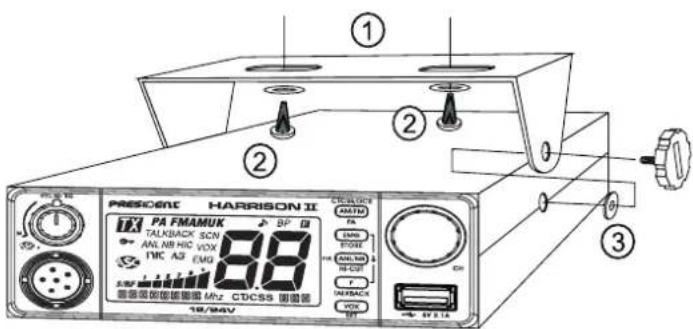
d) To install your equipment, use the cradle (1) and the self-tapping screws (2) provided (drilling diameter 3.2 mm). Take care not to damage the vehicle's electrical system while drilling the dash board.
e) Do not forget to insert the rubber joints (3) between the CB and its support as these have a shock-absorbing effect which permits gentle orientation and tightening of the set.
f) Choose where to place the microphone support and remember that the microphone cord must stretch to the driver without interfering with the controls of the vehicle.
N.B.: As the transceiver has a frontal microphone socket, it can be set into the dash board. In this case, you will need to add an external loud speaker to improve the sound quality of communications (connector EXT SP situated on the back panel: C). Ask your dealer for advice on mounting your CB radio.
2) ANTENNA INSTALLATION
a) Choosing your antenna
- For CB radios, the longer the antenna, the better its results. Your dealer will be able to help you with your choice of antenna.
b) Mobile antenna
- Must be fixed to the vehicle where there is a maximum of metallic surface (ground plane), away from windscreen mountings.
-
If you already have a radio-telephone antenna installed, the transceiver antenna should be higher than this.
-
There are two types of antenna: pre-regulated which should be used on a good ground plane (e.g. car roof or lid of the boot), and adjustable which offer a much larger range and can be used on a smaller ground plane (see § HOW TO ADJUST SWR, below).
- For an antenna which must be fixed by drilling, you will need a good contact between the antenna and the ground plane. To obtain this, you should lightly scratch the surface where the screw and tightening star are to be placed.
- Be careful not to pinch or flatten the coaxial cable (as this runs the risk of break down and/or short-circuiting).
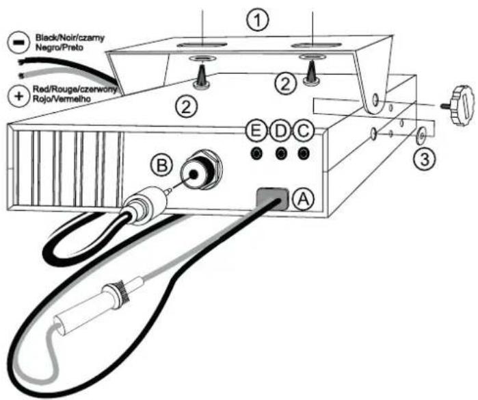
- Connect the antenna (B).
natural_image
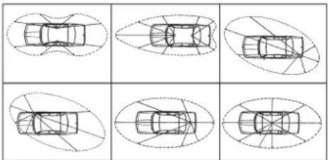
Six identical diagrams of a car viewed from different angles, showing top-down perspective views (no text or symbols)OUTPUT RADIUS PATTERN
c) Fixed antenna
- A fixed antenna should be installed in as clear space as possible. If it is fixed to a mast, it will perhaps be necessary to stay it, according to the laws in force (you should seek professional advice). All PRESIDENT antennas and accessories are designed to give maximum efficiency to each CB radio within the range.
3) POWER CONNECTION
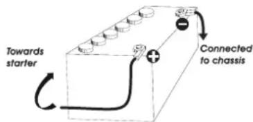
Your PRESIDENT HARRISON II is protected against an inversion of polarities. However, before switching it on, you are advised to check all the connections. Your equipment must be supplied with a continued current of 12 or 24 volts (A). Today, most cars and lorries are negative earth. You can check this by making sure that the negative terminal of the battery is connected either to the engine block or to the chassis. If this is not the case, you should consult your dealer.
a) Check that the battery is of 12 or 24 volts.
b) Locate the positive and negative terminals of the battery (+ is red and - is black). Should it be necessary to lengthen the power cable, you should use the same or a superior type of cable.
c) It is necessary to connect your CB to a permanent (+) and (-). We advise you to connect the power cable directly to the battery (as the connection of the CB cable to the wiring of the car-radio or other parts of the electrical circuit may, in some cases, increase the likelihood of interference).
d) Connect the red wire (+) to the positive terminal of the battery and the black (-) wire to the negative terminal of the battery.
e) Connect the power cable to your CB radio.
WARNING: Never replace the original fuse by one of a different value.
4) BASIC OPERATIONS TO BE CARRIED OUT BEFORE USING YOUR SET FOR THE FIRST TIME (without transmitting and without using the "push-to-talk" switch on the microphone)
a) Connect the microphone.
b) Check the antenna connections.
c) Turn the set on by turning the VOL knob (1) clockwise.
d) Turn the squelch SQ knob (2) to minimum M.
e) Adjust the volume to a comfortable level.
f) Go to channel 20 by using the CH rotary knob (6) or UP/DN keys (13) on the microphone.
5) HOW TO ADJUST SWR (Standing Wave Ratio)
Warning: This must be carried out when you use your radio for the first time and whenever you re-position your antenna. This adjustment must be carried out in an obstacle-free area.
* Adjustment with internal SWR-meter
See function SWR CALIBRATION page 48.
* Adjustment with external SWR-meter (e.g. TOS-1 PRESIDENT)
a) To connect the SWR meter :
- Connect the SWR meter between the CB radio and the antenna as close as possible to the CB (use a maximum of 40 cm cable, type President CA 2C).
b) To adjust the SWR meter:
- Set the CB on channel 20 in AM.

- Put the switch on the SWR-meter to position FWD (calibration).
- Press the PTT "push-to-talk" switch (12) on the microphone to transmit.
- Bring the index needle to ▼ by using the calibration key.
- Change the switch to position REF (reading of the SWR level). The reading on the Meter should be as near as possible to 1. If this is not the case, readjust your antenna to obtain a reading as close as possible to 1. (A SWR reading between 1 and 1.8 is acceptable).
- It will be necessary to recalibrate the SWR meter after each adjustment of the antenna.
WARNING: In order to avoid any losses and attenuations in cables used for connection between the radio and its accessories, PRESIDENT recommends to use a cable with a length inferior to 3 m.
Your transceiver is now ready for use.
B) HOW TO USE YOUR TRANSCEIVER
1) ON/OFF \~ VOLUME
Turn on : turn VOL knob (1) clockwise. If the function KEY BEEP is active (see menu KEY BEEP page 46), the radio emits a beep. The radio is "on". Display briefly shows the frequency band (see § FREQUENCY BAND SELECTION page 44) and the microphone type (consult the MICROPHONE TYPE menu page 47).
Turn Off : turn VOL knob (1) counterclockwise until radio emits click sound. Your radio is "off".
Volume Adjustment: rotate VOL knob (1) clockwise to increase the volume. Turn the same knob counterclockwise to reduce the sound level.
2) ASC (Automatic Squelch Control) \~ SQUELCH
Suppresses undesirable background noises when there is no communication. Squelch does not affect neither sound nor transmission power, but allows a considerable Improvement in listening comfort.
a) ASC: AUTOMATIC SQUELCH CONTROL
Worldwide patent, a PRESIDENT exclusivity.
Turn the SQ knob (2) anti-clockwise into ASC position. 🎨 appears on LCD. No repetitive manual adjustment and a permanent improvement between the sensitivity and the listening comfort when ASC is active. This function can be disconnected by turning the switch clockwise. In this case the squelch adjustment becomes manual again. 🎨 disappears from LCD.
b) MANUAL SQUELCH
Turn the SQ knob (2) clockwise to the exact point where all background noise disappears. This adjustment should be done with precision as, if set to maximum (fully clockwise), only the strongest signals will be received.
3) LCD
Messages part
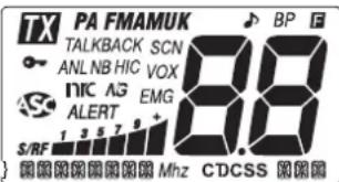
IndicoTX transmission
PA PA (Public Address) mode selected
AM AM mode selected
FM FM mode selected
UK FM mode selected (only in U configuration / ENG)
SCN SCAN function activated
VOX VOX function activated
EMG Emergency channel (1 or 2) is activated
Automatic Squelch Control activated
LOCK function activated
ANL ANL filter is activated
NB NB filter is activated
HIC HI-CUT filter is activated
NG Noise Gate filter is activated
Inrc Compander filter is activated
TALKBACK TALKBACK function activated
ROGER BEEP function activated
BP KEY BEEP function activated
F MENU activated
CTCSS A CTCSS tone is used in the active channel
DCS A DCS code is used in the active channel
5K The channel is stored on the scan skip memory
图图
Indicates the tone or code used
88 Indicates the active channel

TX or RX bargarph
[Non-Text]
Indicates Frequency, Menu or Message
4) AM/FM \~ PA \~ CTCSS/DCS
AM/FM (short press)
This switch allows selecting the modulation mode AM, FM; Your modulation mode has to correspond to the one of your correspondent.
- Amplitude Modulation / AM: communication on a field with relief and obstacles at middle distance (the most used).
- Frequency Modulation / FM: for nearby communications on a flat open field.
In U configuration only: in FM mode, a short press on the F key (9) alternates between the ENG or CEPT frequency bands. "UK" is displayed when the ENG frequency band is selected (see table on page 70).
PA (Public Address) (long press)
An external loud speaker can be connected to the unit by the PA jack plug located on the back panel PA.SP. (D). Turn the VOL knob (1) to adjust the PA volume.
Long press AM/FM key (4) to alternate between CB and PA mode.
For details on operating in PA mode, consult the PA SETTING menu page 47.
CTCSS/DCS
For simplicity, in this manual we will speak of CTCSS/DCS code to indicate both a CTCSS tone and a DCS code, of GENRE to indicate the kind of code (CTCSS, DCS or OFF = no code). TYPE indicates whether this is a TX transmission or an RX reception and MODE specifies the operating mode, Identical Id or different dF.
Consult the CODE SET menu page 48.
See list of codes on pages 73.
Note: Codes can only be used in FM. Each channel can have its own code.
- Press the F key (9). F appears.
- Press the AM/FM key (4) to activate/deactivate the CTCSS/DCS function.
Activation
If a CTCSS/DCS code has been stored, it becomes active, "CTCSS" or "DCS" icon is displayed on the screen.
In MODE Id, If no CTCSS/DCS code has been stored, the device emits an error beep. Go to the CODE SET menu to store a CTCSS/DCS code.
In dF MODE, if no CTCSS/DCS code has been stored in either TYPE TX or TYPE RX, the device emits an error beep. Go to the CODE SET menu to store the CTCSS/DCS codes.
Deactivation
If a CTCSS/DCS code has been stored and "CTCSS" or "DCS" is displayed on the screen, a short press on the AM/FM key (4) after F key (9) deactivates the stored code, "CTCSS" or "DCS" disappears, a deactivation beep sounds. The memorized CTCSS/DCS code is kept in memory but no longer functions.
5) EMERGENCY CHANNELS \~ EMERGENCY CHANNEL SETTING EMERGENCY CHANNELS (short press)
Emergency channels will be automatically selected by pressing the EMG key (5). First press: emergency channel 1 is activated. Second press: emergency channel 2 is activated. Third press: return to the current channel. "EMG" appears on the display when an emergency channel is activated.
See the table page 74 for default emergency channels.
EMERGENCY CHANNEL SETTING
EMG1
-
Using the CH rotary knob (6) select a channel other than an emergency channel. "EMG" must not appear on the display.
-
Press the AM/FM key (4) to select the modulation mode of the selected channel.
-
Long press the EMG key (5). F appears on the display, "EMG" blinks. The message says: EMG: SET.
-
Press the PTT switch (12) ou the F key (9) to validate and exit. IF the KEY BEEP function is activated, a long beep sounds to confirm the success of the operation (consult the KEY BEEP menu page 46).
-
If no key is pressed for 5 seconds, the unit automatically exits EMERGENCY CHANNEL without save.
EMG2
- Using the CH rotary knob (6) select a channel other than an emergency channel. "EMG" must not appear on the display.
- Press the AM/FM key (4) to select the modulation mode of the selected channel.
- Long press the EMG key (5). F appears on the display, "EMG" blinks. The message says: EMG2 SET.
- Turn the CH rotary knob (6) or use the UP/DN keys (13) on the microphone th select the priority channel 2. The message says: EMG2 SET.
- Press the PTT switch (12) ou the F key (9) to validate and exit. IF the KEY BEEP function is activated, a long beep sounds to confirm the success of the operation (consult then KEY BEEP menu page 46).
- If no key is pressed for 5 seconds, the unit automatically exits EMERGENCY CHANNEL without save.
6) ROTARY KNOB
Turn the CH rotary knob (6) to adjust channel. Clockwise to increase, counterclockwise to decrease the channel.
See § UP/DN Keys ON THE MICROPHONE page 44.
7) USB CHARGING SOCKET
The USB socket (9) can be used to charge smartphones, tablets or other rechargeable devices with 5 V - 2.1 A.
8) ANL/NB \~ HI-CUT \~ NRC
ANL/NB (short press)
Short press the ANL/NB key (8) to activate/deactivate the filters in this order:
$$ \boxed {\rightarrow \mathrm{ANL} \rightarrow \mathrm{NB} \rightarrow \mathrm{ANL} + \mathrm{NB} \rightarrow \mathrm{Off}} $$
The activated filter is shown on the display.
ANL - Automatic Noise Limiter: This filter allows the reduction of background noises and some reception interferences. In AM mode only.
NB - Noise Blanker: This filter allows the reduction of back ground noise, and some reception interference.
HI-CUT (long press)
Long press the HI-CUT key (8) to activate/deactivate the HI-CUT filter. "HIC" appears on the display when the filter is active.
Hi-Cut: Eliminates high frequency interferences. Has to be used in accordance with the reception conditions.
NRC
This switchable filter improves the receive and transmit mode.
- Press the F key (9). F appears in the display.
Press the NRC key (8) to activate/deactivate the NRC.
If a R or T value other than has been stored (consult the NRC SET menu page 48), otherwise the display indicates NRC SET
When the NRC is active, " nrc" appears on the display.
Allows to set/validate functions (see for example § VOX SETTING above). This key pressed alone don't have any use.
See § FREQUENCY BAND SELECTION page 44.
See § TALKBACK page 45.
SKIP (long press only if the SCAN function is activated)
This function allows you to skip a channel found by the SCAN function. When the scan stops on an unwanted channel, press and hold the F key (9) for 1 second to store this channel in the SCAN SKIP memory. A beep sounds. The channel will no longer be scanned. See the § SCAN page 44.
Consult the SCAN SKIP menu page 47 and the RESET menu page 49.
MENU (short press + long press)
Press F key (9) first time. F is displayed. Long press F key (9) second time to enter the MENU
See § MENU page 45.
10) VOX \~ VOX SETTING
VOX (short press)
The VOX function allows transmitting by speaking into the original microphone (or in the optional vox microphone) without pressing the PTI switch (12). The use of an optional vox microphone connected to the rear panel of the transceiver (C) disables the original microphone.
Short press the VOX key (10) in order to activate the VOX function. "VOX" appears on the display. Short press again the VOX key (10) to disable the function. "VOX" disappears.
VOX SETTING (long press)
- Long press the VOX key (10) to enter the VOX SETTING. "VOX" blinks, the current setting and its value appear on the display. Three parameters allow to adjust the VOX: Sensitivity SE Anti-vox level / Vox delay R time SET, {
2a. Turn the CH rotary knob (6) or use the UP/DN keys (13) on the microphone to modify the current parameter then, press the F key (9) to select next parameter or....
2b. Press first the F key (9) to select another the parameter and then turn the CH rotary knob (6) or use the UP/DN keys (13) on the microphone to modify the current parameter. - When all adjustments are done, press PTT switch (12) to store and exit. If the KEY BEEP function is activated, a long beep sounds to confirm the success of the operation (consul the KEY BEEP menu page 46).
- If no key is pressed for 10 seconds, the unit automatically exits the function VOX SETTING without save.
- Sensitivity SET: L: allows the adjustment of the microphone (original one or optional vox) for an optimum transmission quality. Adjustable level from 1 (high level) to 9 (low level). Default value: 5.
- Anti-Vox SET, R: allows disabling the transmission generated by the surrounding noise. The level is adjustable. RF (according the squelch level) and from 0 (without anti-vox) to 9 (low level). Default value: RF,
- Delay time SET, & allows avoiding the sudden cut of the transmission by adding a delay at the end of speaking. The level is adjustable from 1 (short delay) to 9 (long delay). Default value: 1.
VOX SETTING doesn't activate the VOX function.
11) 6 PIN MICROPHONE PLUG
The plug is located on the front panel of the transceiver and makes the setting of the equipment into the dashboard easier.
See Cabling Diagram page 73.
12) PTT (Push To Talk)
Transmission key, press to transmit a message, TX is displayed and release to listen to an incoming communication, TX disappears.
TOT (Time Out Timer)
If the transmission using PTT switch (12) or VOX function is longer than 3 minutes, the display starts blinking and the transmission ends. A beep will sound until the PTT switch (12) key is released.
13) UP/DN KEYS ON MICROPHONE \~ SCAN
UP/DN KEYS ON MICROPHONE (short press)
Press UP/DN keys (13) on the microphone to change the channel. UP to increase and DN to decrease the channel.
See ROTARY KNOB page 43.
SCAN (very long press)
Press and hold the UP or DN key (13) for ± 7 seconds or until a beep sounds (consult the KEY BEEP menu page 46) to activate the SCAN function. "SCN" appears on the display. The scanning stops as soon as there is a busy channel. Consult the SCAN TYPE menu page 47. In SCANNING mode, turn the CH rotary knob (6) or press the UP/DN keys (13) on the microphone to change scan direction.
Press PTT switch (12) to exit SCAN. "SCN" disappears on the display. See the § SKIP page 43.
5 + 9) KEY LOCK (EMG + F keys)
Long press simultaneously the EMG (5) and F (9) keys to activate/deactivate the KEY LOCK function. When the function is active, "O" appears on the display.
A) DC-POWER TERMINAL (13.2 V / 26.4 V)
B) ANTENNA CONNECTOR (SO-239)
C) JACK FOR OPTIONAL VOX MICROPHONE (∅ 2.5 mm)
D) PA SPEAKER JACK (8 Ω, ∅ 3.5 mm)
E) JACK FOR EXTERNAL OPTIONAL SPEAKER (8 Ω, ∅ 3.5 mm)
C) FUNCTIONS TURNING ON THE UNIT
(Configuration: EU; PL; d; EC; U; In)
The frequency bands have to be chosen according to the country of use. Don't use any other configuration. Some countries need a user's licence. See table page 75.
-
Turn on the power while pressing the F key (9). The letter corresponding to the current configuration is blinking.
-
In order to change the configuration, use the CH rotary knob (6) on the unit or the UP/DN keys (13) on the microphone.
-
When the configuration is selected, press the F key (9) during 1 second. The letter corresponding to the configuration is continuously displayed and a confirmation beep sounds.
-
At this point, confirm the selection by switching off the transceiver and then switching it on again.
See the frequency bands table at pages 70 to 72 / configuration table page 74.
D) FUNCTIONS WITH THE PTT SWITCH
1) TALKBACK
This function allows you to hear your own modulation in the optional internal or external speaker connected to the EXT.SP jack (E).
Press and hold the PTT switch (12) then press the F key (9) to activate / deactivate the TALKBACK function.
When the function is active, "TALKBACK" blinks on the display for 3 seconds, displaying the current level of the TALKBACK and then remains permanently displayed.
2) TALKBACK LEVEL
This function allows to adjust the volume level of the TALKBACK.
- Activate the TALKBACK function.
- Press and hold the PTT switch (12) then turn the CH rotary knob (6) to increase (clockwise) / decrease (counterclockwise) the volume level of the TALKBACK.
- Release the PTT switch (12).
3) NOISE GATE (PTT + VOX)
- Press and hold the PTT switch (12).
- Short press the VOX key (10) to activate (On) or deactivate (OF) the NOISE GATE. "AG" is displayed when the function is active.
Noise Gate: Prevents amplification of background noise. This results in optimized signal levels.
4) REPEATER / RELAY (PTT + AM/FM)
WARNING! This function is valid only on the D frequency band. See the configuration table page 74.
This function allows you to increase the range of your transceiver.
The radio receives on the current channel and transmits on the defined channel.
To activate this function you must define a TX channel (See REPEATER/RELAY SETTING menu page 49).
- Press and hold the PTT switch (12).
- Short press the AM/FM key (4) to activate RPT ON or deactivate RPT OFF the REPETER/RELAY function. The selection or "RPT x SET", if the transmission channel has not still been selected, blinks during 3 seconds.
E) MENU
The order of 15 menus is as described in this manual. However, the menu displayed by entering the MENU will be the last menu modified by user. The procedure is the same whatever the function is:
Press F key (9). F is displayed.
Long press F key (9) to enter the MENU.
- Turn the CH rotary knob (6) or use UP/DN keys (13) on the microphone to select the menu to set.
- Press EMG key (5) to validate. The current color blinks on the display.
- Turn the CH rotary knob (6) or use UP/DN keys (13) on the microphone to modify the value of the parameter.
- New press on EMG key (5) to validate the chosen value. The parameter stops blinking and if the function has more than one parameter, the next parameter blinks.
- If no key is pressed, the unit exits MENU after 10 seconds. F disappears from the display.
Note: UP/DN keys (13) on the microphone have the same effect as the rotation of the CH rotary knob (6). PTT switch (12) validates the last setting and exists MENU. F disappears.
1) COLOR
Press F key (9). F is displayed.
Long press F key (9) to enter the MENU.
- Turn the CH rotary knob (6) or use UP/DN keys (13) on the microphone to select the COLOR menu.
- Press EMG key (5) to validate. The current color blinks on the display.
- Turn the CH rotary knob (6) or use UP/DN keys (13) on the microphone to modify the color of the display.
orange / green / blue / cyan / yellow / purple / cyan light Or / Gr / bl / cy / YE / PU / CL
-
Short press the EMG key (5) to validate. a) Return to the point 1 to set another menu or b) Short press the F key (9) to validate and exit the MENU. F disappears from the display.
-
If no key is pressed, the unit exits MENU after 10 seconds. F disappears from the display.
Default COLOR is: Or (orange).
2) DIMMER
DIMMER function allows adjusting the brightness of the lighting. 10 steps from 0 to 9
Press F key (F). is displayed.
Long press F key (9) to enter the MENU.
-
Turn the CH rotary knob (6) or use UP/DN keys (13) on the microphone to select the Jmmur
-
Press EMG key (5) to validate. The current value blinks on the display.
-
Turn the CH rotary knob (6) or use the UP/DN keys (13) on the microphone to change the value of the dimmer.
-
Short press the EMG key (5) to validate. a) Return to the point 1 to set another menu or b) Short press the F key (9) to validate and exit the MENU. F disappears from the display.
-
If no key is pressed, the unit exits MENU after 10 seconds. F disappears from the display.
Dimmer default value is : 5.
3) TONE
This function allows to change the RX TONE. 11 steps from -5 to +5
Press F key (F), is displayed.
Long press F key (9) to enter the MENU.
-
Turn the CH rotary knob (6) or use UP/DN keys (13) on the microphone to select the T menu.
-
Press EMG key (5) to validate. The current value blinks on the display.
-
Turn the CH rotary knob (6) or use the UP/DN keys (13) on the microphone to change the value of the tone.
-
Short press the EMG key (5) to validate. a) Return to the point 1 to set another menu or b) Short press the F key (9) to validate and exit the MENU. F disappears from the display.
-
If no key is pressed, the unit exits MENU after 10 seconds. F disappears from the display.
Tone default value is : ☐
4) KEY BEEP
When the function is activated, a beep sounds when a key is pressed, by changing the channel etc. "BP" appears on the display when the function is active.
Press F key (F). is displayed.
Long press F key (9) to enter the MENU.
-
Turn the CH rotary knob (6) or use UP/DN keys (13) on the microphone to select the H00EN/EEP
-
Press EMG key (5) to validate. The current value blinks on the display.
-
Turn the CH rotary knob (6) or use the UP/DN keys (13) on the microphone to activate (on) / deactivate (oF) the function.
-
Short press the EMG key (5) to validate. a) Return to the point 1 to set another menu or b) Short press the F key (9) to validate and exit the MENU. F disappears from the display.
-
If no key is pressed, the unit exits MENU after 10 seconds. F disappears from the display.
Default KEY BEEP is On.
5) ROGER BEEP
When the function is active, the icon 🧑 appears on the display.
The Roger Beep sounds when the PTT switch (12) on the microphone is released in order to let your correspondent speak. Historically as transceiver is a "simplex" communication mode, it is not possible to speak and to listen at the same time (as it is the case with a telephone). Once someone had finished talking, he said "Roger" in order to prevent his correspondent that it was his turn to talk. The word "Roger" has been replaced by a significant beep. There comes "Roger beep" from.
Press F key (P) is displayed.
Long press F key (9) to enter the MENU.
-
Turn the CH rotary knob (6) or use UP/DN keys (13) on the microphone to select the RG BEEP menu.
-
Press EMG key (5) to validate. The current value blinks on the display.
-
Turn the CH rotary knob (6) or use the UP/DN keys (13) on the microphone to activate (I to B^* ) / deactivate (DF) the function.
-
Short press the EMG key (5) to validate. a) Return to the point 1 to set another menu or b) Short press the F key (9) to validate and exit the MENU. F disappears from the display.
-
If no key is pressed, the unit exits MENU after 10 seconds. F disappears from the display.
*6 roger tones for ROGER BEEP.
Default ROGER BEEP is OF.
6) SCAN TYPE
Allows to select the TYPE of SCAN.
Press F key (F), is displayed. Long press F key (9) to enter the MENU.
- Turn the CH rotary knob (6) or use UP/DN keys (13) on the microphone to select the SEN TYPE menu.
- Press EMG key (5) to validate. The current value blinks on the display.
- Turn the CH rotary knob (6) or use the UP/DN keys (13) on the microphone to select the scan type 59 or E1.
- Short press the EMG key (5) to validate. a) Return to the point 1 to set another menu or b) Short press the F key (9) to validate and exit the MENU. F disappears from the display.
- If no key is pressed, the unit exits MENU after 10 seconds. F disappears from the display.
“59”means scanning stops when busy channel is founded.
"E" means scanning stops when busy channel is founded and return to scan after 5 seconds.
Type default value is : 59.
7) SCAN SKIP
This function allows to memorize/erase a channel form the SCAN SKIP memory.
- Select a channel
- Press F key (9). F is displayed.
- Long press F key (9) to enter the MENU.
- Turn the CH rotary knob (6) or use UP/DN keys (13) on the microphone to select the Smengk IP
- Press EMG key (5) to validate. The current value blinks on the display.
- Turn the CH rotary knob (6) or use the UP/DN keys (13) on the microphone to alternate between _n and _F .
- Short press the EMG key (5) to validate. a) Return to the point 1 to set another menu or b) Short press the F key (9) to validate and exit the MENU. F disappears from the display.
- If no key is pressed, the unit exits MENU after 10 seconds. F disappears from the display.
On memorize the current channel into the SCAN SKIP memory. When a channel is stored in the memory, SK appears on the display close to the channel number.
OF erase the current channel from the SCAN SKIP memory, SK disappears from the display.
See the § SKIP on page 43.
8) PA SETTING
This function allows to select the operating mode of Public Address.
Press F key (F). Is displayed.
Long press F key (9) to enter the MENU.
- Turn the CH rotary knob (6) or use UP/DN keys (13) on the microphone to select the PR SET menu.
- Press EMG key (5) to validate. The current value blinks on the display.
- Turn the CH rotary knob (6) or use the UP/DN keys (13) on the microphone to select the operating mode of the PA: in, OF or PR.
- Short press the EMG key (5) to validate. a) Return to the point 1 to set another menu or b) Short press the F key (9) to validate and exit the MENU. F disappears from the display.
- If no key is pressed, the unit exits MENU after 10 seconds. F disappears from the display.
In: the modulation of the microphone is transmitted to the external loudspeaker connected to jack PA.SP. (D). The received signal is transmitted to the internal loudspeaker (or external optional loudspeaker connected to jack EXT.SP (E)). "PA" blinks alternately with the modulation mode (AM or FM).
DF: The reception is no more functional. Only the modulation of the microphone is transmitted to the Public Address loudspeaker connected to jack PA.SP. (D). PR and le level of the PA are displayed.
PA: the modulation of the microphone and the received signal are transmitted to the Public Address loudspeaker connected to jack PA.SP. (D). "PA" blinks alternately with the modulation mode (AM or FM).
Turn the VOL knob (1) to adjust the audio level of the mode PA.
Default PA setting is in
See § PA (Public Address) page 42.
9) MICROPHONE TYPE
PRESIDENT HARRISON II can be used with both a PRESIDENT electret and dynamic 6-pin microphone (see microphone wiring on page 73). When the unit is turned on, the microphone type is displayed briefly.
Press F key (P) is displayed.
Long press F key (9) to enter the MENU.
- Turn the CH rotary knob (6) or use UP/DN keys (13) on the microphone to select the MIC TYPE menu.
-
Press EMG key (5) to validate. The current value blinks on the display.
-
Turn the CH rotary knob (6) or use the UP/DN keys (13) on the microphone to select the microphone type EL (electret) or d4 dynamic.
- Short press the EMG key (5) to validate. a) Return to the point 1 to set another menu or b) Short press the F key (9) to validate and exit the MENU. F disappears from the display.
- If no key is pressed, the unit exits MENU after 10 seconds. F disappears from the display.
Microphone type default is EL (electret).
10) SWR CALIBRATION
This function allows you to adjust the SWR by beeping.
Press F key (F). is displayed. Long press F key (9) to enter the MENU.
- Turn the CH rotary knob (6) or use UP/DN keys (13) on the microphone to select the SWR menu.
- Press the EMG key (5) to confirm. The radio automatically switches to TX mode without pressing the PTT switch (12) and calibration begins. Calibration time is 5 minutes maximum. A countdown is done in the display.
- Adjust the antenna.
- The beep* is continuous when the SWR value is 10. The space between the beeps becomes larger and larger as the SWR value moves away from 10.
- The volume of the beep is adjustable with the VOL knob (1).
- The display shows the SWR value, for example 25.
- Press the PTT switch (12) to exit the SWR CALIBRATION.
*Check that the beep volume is set to a suitable level.
See ADJUSTMENT OF SWR page 40.
11)NRC SET
The NRC filter can be set independently in transmission (T) as in reception (R).
Press F key (F), is displayed. Long press F key (9) to enter the MENU.
- Turn the CH rotary knob (6) or use UP/DN keys (13) on the microphone to select the menu. The last parameter used and its value appears on the display.
- Press the EMG key (5) to confirm. The parameter blinks, R or T.
- Turn the CH rotary knob (6) or use the UP/DN keys (13) on the microphone to select R(reception) or (transmission).
- Press the EMG key (5) to confirm. The value of the filter blinks.
-
Turn the CH rotary knob (6) or use the UP/DN keys (13) on the microphone to change the value from 0 to 5.
-
Short press the EMG key (5) to validate. a) Return to the point 1 to set another menu or b) Short press the F key (9) to validate and exit the MENU. F disappears from the display.
The default value are ☐ (transmission) and ☐ (reception)
See the § NRC page 43 to activate/deactivate the function.
12) VOLUME ACCESSORY
This function allows you to control the volume of the unit and an accessory plugged on the 6-pin plug (accessory available soon).
Press F key (F), is displayed. Long press F key (9) to enter the MENU.
- Turn the CH rotary knob (6) or use UP/DN keys (13) on the microphone to select the VarenOCC
- Press EMG key (5) to validate. The current value blinks on the display.
- Turn the CH rotary knob (6) or use the UP/DN keys (13) on the microphone to select 0, 1 or 2.
- Short press the EMG key (5) to validate. a) Return to the point 1 to set another menu or b) Short press the F key (9) to validate and exit the MENU. F disappears from the display.
- If no key is pressed, the unit exits MENU after 10 seconds. F disappears from the display.
☐ - the vol knob (1) affects the internal speaker volume.
I - the vol knob (1) affect the accessory volume
2 - the vol knob (1) affects both the internal speaker and accessory volume. Default accessory volume is 0.
13) CODE SET
For simplicity, in this manual we will speak of CTCSS/DCS code to indicate both a CTCSS tone and a DCS code, of GENRE to indicate the kind of code (CTCSS, DCS or OFF = no code). TYPE Indicates whether this is a TX transmission or an RX reception and MODE specifies the operating mode, Identical Id or different DF. See § CTCSS/DCS page 42.
This menu allows you to configure the operating mode of the CTCSS/DCS function and to store the CTCSS/DCS codes.
2 operating modes:
- Id means that the code used will be identical for transmission (TX) and for reception (RX).
- dF means that the user can use one code (or OFF = no code) for transmission (TX) and another (or OFF = no code) for reception (RX).
Press F key (F). is displayed.
Long press F key (9) to enter the MENU.
OPERATING MODE
- Turn the CH rotary knob (6) or use the UP/DN keys (13) on the microphone to select the menu.
- Briefly press the EMG key (5) to confirm. The operating mode flashes (id or dF).
- Turn the CH rotary knob (6) or use the UP/DN keys (13) on the microphone to select the desired operating mode.
STORING A CTCSS/DCS CODE
Depending on the operating mode used, the procedure differs:
Identical mode id
- A short press on the EMG key (5) makes the genre blink ("CTCSS", "DCS" or "OFF" no genre).
- Turn the CH rotary knob (6) or use the UP/DN keys (13) on the microphone to select the genre or...
- Press the EMG key (5) to confirm the genre. The code value flashes (unless OFF selected).
- Turn the CH rotary knob (6) or use the UP/DN keys (13) on the microphone to select the code (from 01 to 38 for CTCSS and 001 to 104 for DCS).
Different Mode dF
- A short press on the EMG key (5) makes the type Rx blink.
- Turn the CH rotary knob (6) or use the UP/DN keys (13) on the microphone to select the RX or TX type.
- A short press on the EMG key (5) validates the choice of type. The genre value flashes ("CTCSS", "DCS" or "OFF" no genre).
- Turn the CH rotary knob (6) or use the UP/DN keys (13) on the microphone to select the genre or...
- Press the EMG key (5) to confirm the genre. The code value flashes (unless OFF has been selected).
- Turn the CH rotary knob (6) or use the UP/DN keys (13) on the microphone to select the code (01 to 38 for CTCSS 001 to 104 for DCS).
- Press the EMG key (5) to confirm the selected code. The unit return to point 5, for set the second type.
- If you don't need to set the second type, long press the EMG key (5) to validate and exit the MENU.
- If no key is pressed, the device exits the MENU after 10 seconds without saving the changes.
The default mode is Id (Identical). The default genre is OFF.
See the RESET menu.
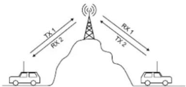
14) REPEATER / RELAY setting
WARNING! This function is valid only on the D frequency band. See the configuration table page 74.
This function allows you to increase the range of your CB.
The radio receives on the current channel RX1 and transmits on the selected channel TX2.
- Select the RX1 channel.
- Press F key (9). F is displayed.
- Long press F key (9) to enter the MENU.
- Turn the CH rotary knob (6) or use UP/DN keys (13) on the microphone to select the RPTX SET menu.
- Short press on the EMG key (5). The current transmission channel RX2 blinks on the display.
- Turn the CH rotary knob (6) or use UP/DN keys (13) on the microphone to select the transmission channel (TX2) or Id (identical, no repeater).
- New press on the EMG key (5) to validate. a) Return to the point 1 to set another menu or b) Short press the F key (9) to validate and exit the MENU. F disappears from the display.
- If no key is pressed, the unit exits MENU after 10 seconds. F disappears from the display.
The default transmission channel is Id (identical RX channel).
To activate the function, see the § REPEATER/RELAY page 45.
15) RESET
This function allows to Erase the scan skip memory or restore all factory settings.
Press F key is displayed.
Long press F key (9) to enter the MENU.
- Turn the CH rotary knob (6) or use UP/DN keys (13) on the microphone to select the RESET menu.
-
Press EMG key (5) to validate. The current value blinks on the display.
-
Turn the CH rotary knob (6) or use the UP/DN keys (13) on the microphone to select SC or RL.
- Short press the EMG key (5) to validate. a) Return to the point 1 to set another menu or b) Short press the F key (9) to validate and exit the MENU. F disappears from the display.
- If no key is pressed, the unit exits MENU after 10 seconds. F disappears from the display.
5C erase all the channels stored on the SCAN SKIP memory. They are now enabled to be scanned (see the § SKIP page 43).
RL restore all the factory parameters.
F) TECHNICAL CHARACTERISTICS
1) GENERAL
- Channels : 40
- Modulation modes : AM / FM
- Frequency ranges : from 26.965 MHz to 27.405 MHz
- Antenna impedance : 50 ohms
- Power supply : 13.2 V / 26.4 V
- Dimensions : 125 (L) x 165 (P) x 45 (H) mm
- Weight : 0.571 kg
- Accessories supplied : 1 microphone electret UP/DOWN with support, mounting cradle, screws and fused power cord.
2) TRANSMISSION
- Frequency allowance : +/- 200 Hz
- Carrier power : 4 W AM / 4 W FM
- Transmission interference : inferior to 4 nW (-54 dBm)
- Audio response : 300 Hz to 3 KHz In AM/FM
- Emitted power in the adj. channel : inferior to 20 μW
- Microphone sensitivity : 3.0 mV
- Drain : <2 A max. with modulation (13.2 V) < 1 A max. with modulation (26.4 V)
- Modulated signal distortion : 2%
3) RECEPTION
- Maxi. sensitivity at 20 dB sinad : 0.5 μV - 113 dBm (AM)
0.35 μV - 116 dBm (FM) - Frequency response : 300 Hz to 3 kHz in AM/FM
- Adjacent channel selectivity : 60 dB
-
Maximum audio power : 3 W
-
Squelch sensitivity : minimum 0.2 μV - 120 dBm
maximum 1 mV - 47 dBm - Frequency image rejection rate : 60 dB
- Intermediate frequency rej. rate : 70 dB
- Drain : 180 \~ 500 mA maximum (13.2 V)
90 \~ 250 mA maximum (26.4 V)
G) TROUBLE SHOOTING
1) YOUR RADIO WILL NOT TRANSMIT OR YOUR TRANSMISSION IS OF POOR QUALITY
- Check that the antenna is correctly connected and that the SWR is properly adjusted.
- Check that the microphone is properly plugged in.
- You are using the same modulation mode than your correspondent.
- Check that the programmed configuration is the correct one (see table page 74).
2) YOUR RADIO WILL NOT RECEIVE OR RECEPTION IS POOR
- Check that the squelch level is properly adjusted.
- Check that the volume (1) is set to a comfortable listening level.
- Check that the antenna is correctly connected and that the SWR is properly adjusted.
- Check that you are using the same modulation mode as your correspondent.
- Check that the programmed configuration is the correct one (see table page 74).
- Consult the VOLUME ACCESSORY menu page 48.
- Check that you are not using any CTCSS/DSC code (See the § CTCSS/DSC page 42
- Check the power supply.
- Check the connection wiring.
- Check the fuse.
H) HOW TO TRANSMIT OR RECEIVE A MESSAGE?
Now that you have read the manual, make sure that your CB Radio is ready for use (i.e. check that your antenna is connected).
Press the «push-to-talk» switch (12) and announce your message «Attention
stations, transmission testing» which will allow you to check the clearness and the power of your signal. Release the switch and wait for a reply. You should receive a reply like, «Strong and clean».
If you use a calling channel (19) and you have established communication with someone, it is common practice to choose another available channel so as not to block the calling channel.
I) GLOSSARY
INTERNATIONAL PHONETIC ALPHABET
| A | Alpha | H | Hotel | O | Oscar | V | Victor |
| B | Bravo | I | India | P | Papa | W | Whiskey |
| C | Charlie | J | Juliett | Q | Quebec | X | X-ray |
| D | Delta | K | Kilo | R | Romeo | Y | Yankee |
| E | Echo | L | Lima | S | Sierra | Z | Zulu |
| F | Foxtrot | M | Mike | T | Tango | ||
| G | Golf | N | November | U | Uniform |
TECHNICAL VOCABULARY
| AM | : Amplitude Modulation |
| CB | : Citizen's Band |
| CH | : Channel |
| CW | : Continuous Wave |
| DX | : Long Distance Liaison |
| DW | : Dual Watch |
| FM | : Frequency Modulation |
| GMT | : Greenwich Meantime |
| HF | : High Frequency |
| LF | : Low Frequency |
| LSB | : Lower Side Band |
| RX | : Receiver |
| SSB | : Single Side Band |
| SWR | : Standing Wave Ratio |
| SWL | : Short Wave Listening |
| SW | : Short Wave |
| TX : CB Transceiver | |
| UHF | : Ultra High Frequency |
| USB | : Upper Side Band |
| VHF | : Very High Frequency |
CB LANGUAGE
| Advertising | : Flashing lights of police car |
| Back off | : Slow down |
| Basement | : Channel 1 |
| Base station | : A CB set in fixed location |
| Bear | : Policeman |
| Bear bite | : Speeding fine |
| Bear cage | : Police station |
| Big slab | : Motorway |
| Big 10-4 | : Absolutely |
| Bleeding | : Signal from an adjacent channel interfering with the transmission |
| Blocking the channel | : Pressing the PTT switch without talking |
| Blue boys | : Police |
| Break | : Used to ask permission to join a conversation |
| Breaker | : A CBer wishing to join a channel |
| Clean and green | : Clear of police |
| Cleaner channel | : Channel with less interference |
| Coming in loud and proud : Good reception | |
| Doughnut | : Tire |
| Down and gone | : Turning CB off |
| Down one | : Go to a lower channel |
| Do you copy? | : Understand? |
| DX | : Long distance |
| Eighty eights | : Love and kisses |
| Eye ball | : CBers meeting together |
| Good buddy | : Fellow CBer |
| Hammer | : Accelerator |
| Handle | : CBer's nickname |
| Harvey wall banger | : Dangerous driver |
| How am I hitting you? | : How are you receiving me? |
| Keying the mike | : Pressing the PTT switch without talking |
| Kojac with a kodak | : Police radar |
| Land line | : Telephone |
| Lunch box | : CB set |
| Man with a gun | : Police radar |
| Mayday | : SOS |
| Meat wagon | : Ambulance |
| Midnight shopper | : Thief |
Modulation : Conversation
Negative copy : No reply
Over your shoulder : Right behind you
Part your hair : Behave yourself - police ahead
Pull your hammer back : Slow down
Rat race : Congested traffic
Rubberbander : New CBer
Sail boat fuel : Wind
Smokey dozing : Parked police car
Smokey with a camera : Police radar
Spaghetti bowl : Interchange
Stinger : Antenna
Turkey : Dumb CBer
Up one : Go up one channel
Wall to wall : All over/everywhere
What am I putting to you? : Please give me an S-meter reading
SIMPLIFIED EU DECLARATION OF CONFORMITY
Hereby, Groupe President Electronics, declares that the CB radio equipment :
Brand: PRESIDENT
Type: TXPR668
Commercial Name: HARRISON II
is in compliance with Directive 2014/53/EU.
The full text of the EU declaration of conformity is available at the following internet address:
https://president-electronics.com/DC/TXPR668.
SIMPLIFIED UK DECLARATION OF CONFORMITY
Hereby, Groupe President Electronics, declares that the CB radio equipment :
Brand: PRESIDENT
Type: TXPR668
Commercial Name: HARRISON II
Is in conformity with the relevant regulatory requirements.
The full text of the UKCA declaration of conformity is available at the following internet address:
https://president-electronics.com/DC/TXPR668.
GENERAL WARRANTY CONDITIONS
This device is guaranteed 2 years parts and labor in its country of purchase against any manufacturing defects validated by our technical department. *The After-sales Service of PRESIDENT reserves the right not to apply the warranty if a breakdown is caused by an antenna other than those distributed by PRESIDENT, and if said antenna is at the origin of the breakdown. An extension of 3 years warranty is proposed systematically for the purchase and use of a PRESIDENT antenna, bringing the total duration of the warranty to 5 years. In order to be valid, the warranty certificate must be returned within a period of 30 days after the purchase date to the After-sales Service of the company Groupe President Electronics, or any foreign subsidiary.
It is recommended to carefully read the following conditions and to respect them under penalty of losing their benefit.
- To be valid the warranty certificate must be returned to us at the latest 1 month after the purchase.
- Please duly complete the warranty certificate on the right hand side of the page, detach it (portion to be removed marked by dotted line) and send it back.
- Any repair under warranty will be free and the return delivery costs will be covered by our company.
- A purchase proof must be necessarily included with the device to be repaired.
- The dates listed on the warranty certificate and proof of purchase must match.
- Do not proceed with the installation of the device without reading the user manual.
- No spare part will be sent nor exchanged by our services under warranty.
The warranty is only valid in the country of purchase.
Exclusions (are not covered):
- Damages caused by accident, shock or inadequate packaging.
- Power transistors, microphones, lights, fuses and the non respect of the installation and use of specifications (including but not limited to antenna used with too high power, final output power transistors (SWR), inversion of polarities, bad connections, overvoltage,...)
- The warranty cannot be extended due to the non-availability of the device while it is being serviced at our technical services location, nor by a change of one or more components or spare parts.
- Transceivers which have been modified. The warranty application is excluded in case of modification or poor maintenance done by a third party not approved by our company.
If you note malfunctions:
- Check the power supply of your device and the quality of the fuse.
-
Check that the antenna, the microphone.... are correctly connected.
-
Check that the squelch level is properly adjusted; the programmed configuration is the correct one...
- In case the device is not under warranty, the repair and return of the device will be charged.
- All related documents must be preserved even after the end of the warranty period and if you resell your device, given to the new owner for the After-sales follow-up.
- In case of real malfunction, please contact your dealer first; they will decide action to be taken.
- In case of an intervention not covered by the warranty, an estimate will be established before any repair.
Thank you for your trust in the PRESIDENT quality and experience. We recommend that you read this manual carefully so that you are completely satisfied with your purchase. Do not forget to return the detachable warranty certificate on the right hand side of this page; it is very important for the identification of your device during a possible rendering of our services.

Technical Manager and Quality Manager


Date of purchase :
Type : CB Radio HARRISON II
Serial N°:

NOT COVERED BY THE WARRANTY WITHOUT THE DEALER STAMP
UWAGA!
natural_image
Six identical diagrams showing a car viewed from different angles, each with dashed and solid outlines (no text or symbols)1) ODSŁUCH WŁASNEJ MODULACJI (TALKBACK)
| A | Alpha | H | Hotel | O | Oscar | V | Victor |
| B | Bravo | I | India | P | Papa | W | Whiskey |
| C | Charlie | J | Juliet | Q | Quebec | X | X-ray |
| D | Delta | K | Kilo | R | Romeo | Y | Yankee |
| E | Echo | L | Lima | S | Sierra | Z | Zulu |
| F | Foxtrot | M | Mike | T | Tango | ||
| G | Golf | N | November | U | Uniform |
TERMINOLOGIA TECHNICZNA
https://president-electronics.com/DC/TXPR668
UPROSZCZONA DEKLARACJA ZGODNOŚCI UK
https://president-electronics.com/DC/TXPR668
OGÓLNE WARUNKI GWARANCJI
FREQUENCY TABLE for d
The frequency band and the transmission power of your transceiver must correspond with the configuration authorized in the country where it is used.
Countries in which there are particular restrictions (Licence ^1 / Register ^2 )