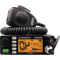
Walker II - Stapler PRESIDENT - Free user manual and instructions
Find the device manual for free Walker II PRESIDENT in PDF.

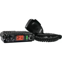
| Product type | Mobile CB transceiver |
| Brand | President |
| Model | Walker II |
| Number of channels | 40 AM/FM channels (expandable depending on configuration) |
| Modulation modes | AM, FM, UK (depending on configuration) |
| Power supply | 13.2 V DC, reverse polarity protection |
| Dimensions (L x W x H) | 170 x 160 x 52 mm |
| Weight | Approximately 1.1 kg |
| Display | LCD with multicolor backlight (7 adjustable colors) |
| Transmit power | 4 W AM / 4 W FM |
| SWR adjustment | Built-in with audio beep indication |
| Reception functions | Squelch (ASC/manual), RF Gain, noise reducers (ANL, NB, HI-CUT) |
| Transmission functions | Adjustable RF Power, MIC Gain, VOX (adjustable), Roger Beep, Talkback |
| Comfort functions | Scan, priority channels (EMG1/2), channel range, key beeps, tone, dimmer |
| USB port | 5 V / 2.1 A charging for external devices |
| Microphone input | 6-pin front panel, compatible with electret and dynamic |
| External speaker | EXT SP jack (rear panel) |
| PA mode (Public Address) | With mode adjustment (In, Ot, Pr) |
| Included accessories | Electret microphone UP/DOWN, holder, mounting bracket, power cord with fuse |
| Warranty | 2 years parts and labor (5 years with President antenna under conditions) |
Frequently Asked Questions - Walker II PRESIDENT
User questions about Walker II PRESIDENT
0 question about this device. Answer the ones you know or ask your own.
Ask a new question about this device
Download the instructions for your Stapler in PDF format for free! Find your manual Walker II - PRESIDENT and take your electronic device back in hand. On this page are published all the documents necessary for the use of your device. Walker II by PRESIDENT.
USER MANUAL Walker II PRESIDENT
PA Mode PA (Public Address) activé
Vox (pression brive)
17) PÉDALE D'ÉMISSION PTT (Push To Talk)
(Configuration: EU; PL; d; EC; U; In)
E) FONCTIONS AVEC LA PEDALE D'EMISSION PTT
H Hotel
1 India
J. Juliet
K Kiko
L Lima
M Mike
N November
Oscar
P Papa
8. Quebec
R Romeo
Sierra
Tango
U Uniform
V Victor
WWhiskey
X X-ray
Y. yankee
Z Zulu
LANGUAGE TECHNIQUE
SW : Short waves (ondes courtes)
BASE: Station de base
https://president-electronics.com/DC/TXPR100.
CONDITIONS GENÉRALES DE GARANTIE
H Hotel
India
J Jullet
K Kilo
L Lima
M Mike
N November
Oscar
P Papa
Quebec
R Romeo
Sierra
Tanga
U Uniform
V Victor
W Whiskey
X X-ray
YYankee
Z Zulu
TERMINOS DEL ARGOT CEBEISTA:
A.L.
ARMONICOS
AVE MARIA
BARBAS
BARRA MOVIL
BASE
BIGOTADA
BREAK
BREAKER
CAJA TONTA
CHICHARRA
CORTINERO
CRUCE DE ANTENAS
DOS METROS HORIZONTALS
ENCENDER FILAMENTOS
ESPIRAS
FOTOCOPIA
FRECUENCIA
KAS
LABORO
LADRILLO
LINEA DE BAJA O LINEA
DE500
MODULAR
O.K.
OKAPA
P.A.
PASTILLA
Before using, be careful never to transmit without first having connected the antenna (connection "B" situated on the back panel of the equipment) or without having set the SWR (Standing Wave Ratio)! Failure to do so may result in destruction of the power amplifier, which is not covered by the guarantee.
MULTI-NORMS TRANSCEIVER!
See function "F" on page 37 and the Configuration table on page 61.
The guarantee of this transceiver is valid only in the country of purchase.
Welcome to the world of the new generation of CB radios. The new PRESIDENT range gives you access to top performance transceiver equipment. With the use of up-to-date technology, which guarantees unprecedented quality, your PRESIDENT WALKER II is a new step in personal communication and is the surest choice for the most demanding of professional CB radio users. To ensure that you make the most of all its capacities, we advise you to read carefully this manual before installing and using your PRESIDENT WALKER II.
A) INSTALLATION
1) WHERE AND HOW TO MOUNT YOUR MOBILE CB RADIO
a) You should choose a well ventilated place most appropriate setting from a simple and practical point of view.
b) Your CB radio should not interfere with the driver or the passengers.
c) Remember to provide for the passing and protection of different wires (e.g. power, antenna, accessory cabling) so that they do not in any way interfere with the driving of the vehicle.
d) To install your equipment, use the cradle (1) and the self-tapping screws (2) provided (drilling diameter 3.2mm ). Take care not to damage the vehicle's electrical system while drilling the dash board.
e) Do not forget to insert the rubber joints (3) between the CB and its support as these have a shock-absorbing effect which permits gentle orientation and tightening of the set.
f) Choose where to place the microphone support and remember that the microphone cord must stretch to the driver without interfering with the controls of the vehicle.
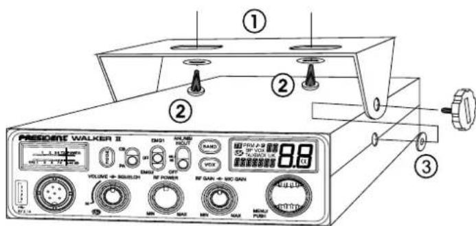
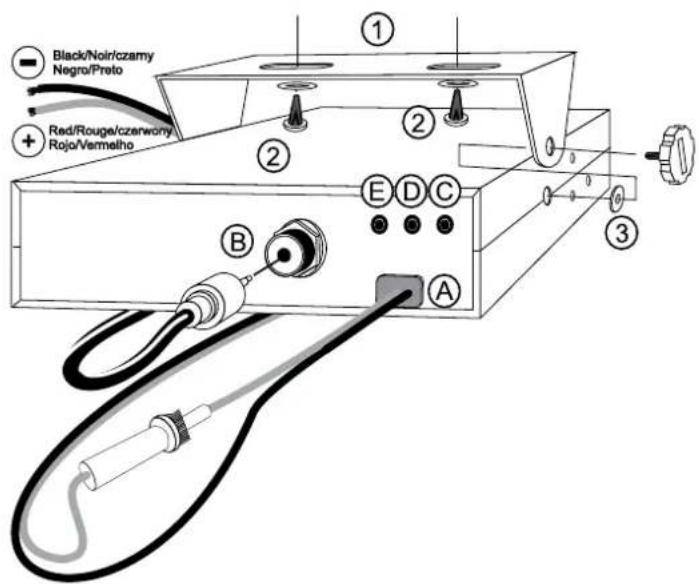
N.B.: As the transceiver has a frontal microphone socket, it can be set into the dash board. In this case, you will need to add an external loud speaker to improve the sound quality of communications (connector EXTSP situated on the back panel: C). Ask your dealer for advice on mounting your CB radio.
2) ANTENNA INSTALLATION
a) Choosing your antenna
- For CB radios, the longer the antenna, the better its results. Your dealer will be able to help you with your choice of antenna.
b) Mobile antenna
- Must be fixed to the vehicle where there is a maximum of metallic surface (ground plane), away from windscreen mountings.
-
If you already have a radio-telephone antenna installed, the transceiver antenna should be higher than this.
-
There are two types of antenna: pre-regulated which should be used on a good ground plane (e.g. car roof or lid of the boot), and adjustable which offer a much larger range and can be used on a smaller ground plane (see § HOW TO ADJUST SWR below).
- For an antenna which must be fixed by drilling, you will need a good contact between the antenna and the ground plane. To obtain this, you should lightly scratch the surface where the screw and tightening star are to be placed.
- Be careful not to pinch or flatten the coaxial cable (as this runs the risk of break down and/or short-circuiting).
- Connect the antenna (B).
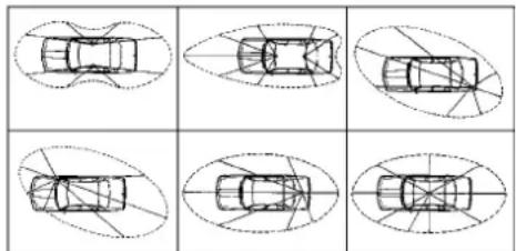
OUTPUT RADIUS PATTERN
c) Fixed antenna
- A fixed antenna should be installed in as clear space as possible. If it is fixed to a mast, it will perhaps be necessary to stay it, according to the laws in force (you should seek professional advice). All PRESIDENT antennas and accessories are designed to give maximum efficiency to each CB radio within the range.
3) POWER CONNECTION
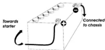
Your PRESIDENT WALKER II is protected against an inversion of polarities. However, before switching it on, you are advised to check all the connections. Your equipment must be supplied with a continued current of 12 volts (A). Today, most cars and lorries are negative earth. You can check this by making sure that the negative terminal of the battery is connected either to the engine block or to the chassis. If this is not the case, you should consult your dealer.
WARNING: Lorries generally have two batteries and an electrical installation of 24 volts, in which case it will be necessary to insert a 24/12 volt converter (type CV 24/12 PRESIDENT) into the electrical circuit. The following connection steps should be carried out with the power cable disconnected from the set.
a) Check that the battery is of 12 volts.
b) Locate the positive and negative terminals of the battery (+ is red and - is black). Should it be necessary to lengthen the power cable, you should use the same or a superior type of cable.
c) It is necessary to connect your transceiver to a permanent (+) and (-). We advise you to connect the power cable directly to the battery (as the connection of the transceiver cable to the wiring of the car-radio or other parts of the electrical circuit may, in some cases, increase the likelihood of interference).
d) Connect the red wire (+) to the positive terminal of the battery and the black (-) wire to the negative terminal of the battery.
e) Connect the power cable to your CB radio.
WARNING: Never replace the original fuse by one of a different value.
4) BASIC OPERATIONS TO BE CARRIED OUT BEFORE USING YOUR SET FOR THE FIRST TIME (without transmitting and without using the "push-to-talk" switch on the microphone)
a) Connect the microphone.
b) Check the antenna connections.
c) Turn the set on by turning the VOLUME knob (1) clockwise.
d) Turn the SQUELCH knob (2) to minimum M.
e) Adjust the volume to a comfortable level.
f) Go to channel 20 by using rotary PUSH knob (6) or UP/DN buttons (18) on the microphone.
5) HOW TO ADJUST SWR (Standing Wave Ratio)
Warning: This must be carried out when you use your radio for the first time and whenever you re-position your antenna. This adjustment must be carried out in an obstacle-free area.
* Adjustment with internal SWR-meter
NEW, EASY AND VERY HANDY- Adjustment of SWR meter by beep tones
See menu SWR ADJUSTMENT function page 39.
- Adjustment with external SWR-meter (e.g. TOS-1 PRESIDENT)
a) To connect the SWR meter :
- Connect the SWR meter between the CB radio and the antenna as close as possible to the CB (use a maximum of 40~cm cable, type President CA 2C).
b) To adjust the SWR meter:
- Set the CB on channel 20 in AM.
Put the switch on the SWR-meter to position FWD (calibration).
Press the PTT "push-to-talk" switch (17) on the microphone to transmit. - Bring the index needle to by using the calibration key.
- Change the switch to position REF (reading of the SWR level). The reading on the Meter should be as near as possible to 1. If this is not the case, readjust your antenna to obtain a reading as close as possible to 1. (A SWR reading between 1 and 1.8 is acceptable).
- It will be necessary to recalibrate the SWR meter after each adjustment of the antenna.
WARNING: In order to avoid any losses and attenuations in cables used for connection between the radio and its accessories, PRESIDENT recommends to use a cable with a length inferior to 3m .
Your transceiver is now ready for use.

B) HOW TO USE YOUR TRANSCEIVER
1) ON/OFF ~ VOLUME
Turn on: turn VOLUME knob (1) clockwise. If the function KEY BEEP is active (see menu KEY BEEP page 37), the radio emits a beep. The radio is "on". Display shows the microphone type setup during 1 second. See menu MIC TYPE page 39.
Turn Off: turn VOLUME knob (1) counterclockwise until radio emits click sound. Your radio is "off".
Volume Adjustment: rotate VOLUME knob (1) clockwise to adjust volume.
Turn the same knob counterclockwise to reduce the sound level.
2) ASC (Automatic Squelch Control) ~ SQUEELCH
Suppresses undesirable background noises when there is no communication.
Squelch does not affect neither sound nor transmission power, but allows a considerable improvement in listening comfort.
a) ASC: AUTOMATIC SQUEELCH CONTROL
Worldwide patent, a PRESIDENT exclusivity.
Turn the SQUELCH knob (2) anti-clockwise into ASC position. 1 appears on LCD. No repetitive manual adjustment and a permanent improvement between the sensitivity and the listening comfort when ASC is active. This function can be disconnected by turning the switch clockwise. In this case, the squelch adjustment becomes manual again. 1 disappears from LCD.
b) MANUAL SQUEELCH
Tum the SQUELCH knob (2) clockwise to the exact point where all background noise disappears. This adjustment should be done with precision as, if set to maximum (fully clockwise), only the strongest signals will be received.
3) RF POWER
In TX mode, turn the RF POWER knob (3) to adjust the AM/FM transmission power; clockwise to increase, counterclockwise to decrease the RF POWER.
4) MIC GAIN
Adjustment of the sensitivity level of the microphone.
The normal position of this function is set to maximum clockwise.
5) RF GAIN
Adjustment of the reception sensitivity. Maximum position in the case of long-distance transmission. You can decrease the RF GAIN, to avoid distortions, when the interlocutor is near. Reduce the gain on reception in the case of a close communication with a correspondent not equipped with a RF POWER.
The normal position of this function is at maximum clockwise.
6) ROTARY "PUSH" KNOB
In normal operation, turn rotary PUSH knob (6) to adjust channel. Clockwise to increase, counterclockwise to decrease the channel.
In MENU mode (long press PUSH knob (6) for 3 seconds to activate this mode (see § MENU page 37)).
- Turn rotary PUSH knob (6) to select the function to set.
- Press PUSH knob (6) to validate. The parameter of the chosen functions blinks on LCD.
- Turn rotary PUSH knob (6) to change the value of the parameter.
- New press PUSH knob (6) to validate the chosen value. The parameter stops blinking and if the function has more than one parameter, the next parameter blinks.
See UP/DN BUTTONS ON THE MICROPHONE page 36.
7) LCD
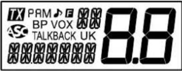
Indica transmission
PA PA (Public Address) mode activated
AM AM mode selected
FM FM mode selected
UK FM mode selected (only in U configuration / ENG)
ROGER BEEP function activated
BP KEY BEEP function activated
Automatic Squelch Control activated
VOX VOX function activated
SCAN function activated (the dot blinks)
TALKBACK TALKBACK function activated
F MENU mode activated
88 Indicates selected channel (large digits)
Indicates selected band (digits on the top)
Indicates frequency or menu
8) VOX VOX SET
VOX(short press)
The VOX function allows transmitting by speaking into the original microphone (or in the optional vox microphone) without pressing the PTT switch (17). The use of an optional vox microphone connected to the rear panel of the transceiver (E) disables the original microphone.
Press shortly VOX key (8) in order to activate the VOX function. "VOX" appears on the display. Press shortly again the VOX key (8) to disable the function. "VOX" disappears.
VOX SET(long press)
Press the VOX key (8) for 2 seconds in order to activate the VOX Adjustment mode.
Three adjustments are possible: Sensitivity SET L / Anti-vox level SET R / Vox delay time SET T (over and over).
- To change a setting other than the one displayed, press the VOX key (8) to select the next setting or...
- Turn the rotary PUSH knob (6) or press the UP/DN (18) keys on the microphone to modify the setting.
- Press again the VOX key (8) to store and move to next setting.
- Once the settings done, press the PTT switch (17) key to exit the VOX Adjustment mode. If no adjustment is made for 5 seconds, the unit automatically exits the function.
Sensitivity 5:1: allows the adjustment of the microphone (original one or optional vox) for an optimum transmission quality. Adjustable level from 2 (high level) to 9 (low level). Default value: 5. - Anti-Vox II: allows disabling the transmission generated by the surrounding noise. The level is adjustable. DF (according the squelich level) and from 0 (without anti-vox) to 9 (low level). Default value: 9.
Delay time SET T: allows avoiding the sudden cut of the transmission by adding a delay at the end of speaking. The level is adjustable from 1 (short delay) to 9 (long delay). Default value: I.
The VOX adjustment does not automatically activate the VOX function.
9) F - FREQUENCY BAND SELECTION
See § FUNCTION TURNING ON THE UNIT page 37.
10)NB/ANL - HIC FILTERS
3 positions switch: Low position: no filter is activated. Central position: only ANL and NB filters are enabled. High position: all filters (ANL, NB and HI-CUT) are activated.
NB: Noise Blanker / ANL: Automatic Noise Limiter. These filters allow reducing back ground noises and some reception interferences.
HI-CUT: Cuts out the high frequency interferences and has to be used in accordance with the reception conditions.
Note: ANL filter works only in AM mode
11) PRIORITY CHANNELS
Priority channels will be automatically selected by switching this key (11). 3 positions switch: EMG1/ Priority channel 1 is activated. EMG2 / Priority
channel 2 is activated. OFF / No priority channel is activated.
The default priority channels are channel 9/AM (EMG1) and channel 19/ AM (EMG2).
See the EMG SET 1 and EMG SET 2 menus page 38 to set priority channels. Note: Activating a priority channel prevents changing the modulation mode (AM / FM / UK), scanning the channels or activating the PA mode. If the KEY BEEP function is activated, an error beep sounds. "EMG" and the channel blink to indicate unauthorized handling. Turn the switch (11) to the OFF position to use these functions.
12)CB/PA
Switch between CB and PA (Public Address) mode.
An external optional speaker can be connected to the unit to the PA,SP. jack on the rear panel. (D). Turn the MIC GAIN knob (4) to adjust the PA volume.
For details on operating in PA mode, see the PA SETTING menu on page 39.
Press MODE key (13) to select the modulation mode: AM or FM. Selected mode is displayed on LCD.
Your modulation mode has to correspond to the one of your correspondent.
Frequency Modulation / FM: for nearby communications on a flat open field.
Amplitude Modulation / AM: communication on a field with relief and obstacles at middle distance (the most used).
In U configuration only: The MODE key (13) allows to select the ENG or CEPT frequency band. "UK" is displayed when the ENG frequency band is selected. When the CEPT frequency band is selected, "UK" disappears from the display (see table on page 57).
14)BARGRAPH
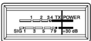
Indicates the reception level and the emitted power level.
The plug is located on the front panel of the transceiver and makes the setting of the equipment into the dashboard easier.
See Cabling Diagram page 60.
16) USB CHARGING SOCKET
The USB socket (16) can be used to charge smartphones, tablets or other rechargeable devices with 5 V - 2.1 A.
17)PTT
Transmission key, press to transmit a message, is displayed and release to listen to an incoming communication, disappears.
TOT (Time Out Timer)
If the PTT switch (17) key is pressed for more than 5 minutes, the display starts blinking and the transmission ends. A beep will sound until the PTT switch (17) key is released.
18) UP/DN BUTTONS ON MICROPHONE SCAN
UP/DN BUTTONS ON MICROPHONE (short press)
In normal use, press UP/DN buttons (18) on the microphone to change the channel. UP to increase and DN to decrease the channel.
In MENU mode (press the PUSH knob (6) for about 3 seconds to activate this mode (see § MENU page 37)), the UP or DN buttons (18) allows to select the menu to be set.
See ROTARY "PUSH" KNOB page 34.
SCAN(long press)
Press and hold the UP or DN button (18) for ± 7 seconds or until a beep sounds to activate the SCAN function. The dot between the two channel digits flashes to indicate that the function is active.
The scanning stops as soon as there is a busy channel. The scanning automatically starts 3 seconds after the end of the transmission and no key is activated during 3 s. In SCANNING mode, turn the PUSH rotary knob (6) or press the UP/DN buttons (18) on the microphone to change scan direction. Press PTT switch (17) to exit SCAN. The dot between the two channel digits disappears from LCD.
A) DC-POWER TERMINAL (13,2 V)
B) ANTENNA CONNECTOR (SO-239)
C) JACK FOR EXTERNAL OPTIONAL SPEAKER (8 Ω, Ø 3.5 mm)
D) JACK FOR PA OPTIONAL SPEAKER (Public Address) (8 Ω, 0.3.5 mm)
E) JACK FOR OPTIONAL VOX MICROPHONE (8 , 2.5mm)
To select the FREQUENCY BAND turn off the unit. Press and hold the F key (9) and then turn the unit on.
(Configuration: EU; PL; d; EC; U; In)
The frequency bands have to be chosen according to the country of use. Don't use any other configuration. Some countries need a user's licence. See table page 62.
- Turn on the power while pressing the F key (9). The letter corresponding to the current configuration is blinking.
- In order to change the configuration, use the PUSH rotary knob (6) on the unit or the UP/DN buttons (18) on the microphone.
- When the configuration is selected, press the F key (9) during 1 second. The letter corresponding to the configuration is continuously displayed and a confirmation beep sounds.
- At this point, confirm the selection by switching off the transceiver and then switching it on again.
See the frequency bands table at pages 57 to 59 / configuration table page 61.
D) MENU
The order of 11 functions is as described in this manual. However, the function displayed by entering the MENU will be the last function modified by user.
The procedure is the same Whatever the function is:
Press PUSH knob (6) for 3 seconds to enter MENU. F is displayed.
- Turn the rotary PUSH knob (6) or use UP/DN buttons (18) on the microphone to select the menu.
- Press PUSH knob (6) to validate. The parameter of the chosen function blinks on the display.
- Turn the rotary PUSH knob (6) or use UP/DN buttons (18) on the microphone to modify the value of the parameter.
- New press PUSH knob (6) to validate the chosen value. The parameter
stops blinking and if the function has more than one parameter, the next parameter blinks.
- If no key is pressed, the unit exits MENU after 10 seconds. disappears from the display.
Note: UP/DN buttons (18) on the microphone have the same effect as the rotation of the rotary PUSH knob (6). PTT switch (17) validates the last setting and exists MENU. Disappears.
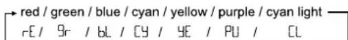
1) COLOR
This function allows to choose the backlight color of the LCD.
Press PUSH knob (6) for 3 seconds to enter MENU. F is displayed.
- Turn the rotary PUSH knob (6) or use UP/DN buttons (18) on the microphone to select the COLOR function.
- Press PUSH knob (6) to validate. The current COLOR blinks on LCD.
- Turn the rotary PUSH knob (6) or use UP/DN buttons (11) on the microphone to select the color. 7 available colors over and over:
- New press PUSH knob (6) to validate the chosen color. The parameter stops blinking. a) Go to point 1 to adjust another function or b) Press the PTT switch (17) to validate and exit MENU. ±b disappears in the display.
- If no key is pressed, the unit exits MENU after 10 seconds, F disappears in the display.
Default COLOR is rE(red).
2) KEY BEEP
When the function is activated, a beep sounds when a key is pressed, by changing the channel etc. "BP" appears on the display when the function is active.
Press PUSH knob (6) for 3 seconds to enter MENU. F is displayed.
- Turn the rotary PUSH knob (6) or use UP/DN buttons (18) on the microphone to select the OK/NEEP function.
- Press PUSH knob (6) to validate. The current status blinks on LCD.
- Turn the rotary PUSH knob (6) or use UP/DN buttons (18) on the microphone to activate On / deactivate Off the function.
- New press PUSH knob (6) to invalidate. The parameter stops blinking. a) Go to point 1 to adjust another function or b) Press the PTT switch (17) to invalidate and exit MENU. 4 disappears.
- If no key is pressed, the unit exits MENU after 10 seconds, F disappears in the display.
Default KEY BEEP is n.
3) ROGER BEEP
When the function is active, the icon appears on the display.
The Roger Beep sounds when the PTT switch (17) on the microphone is released in order to let your correspondent speak. Historically as transceiver is a "simplex" communication mode, it is not possible to speak and to listen at the same time (as it is the case with a telephone). Once someone had finished talking, he said "Roger" in order to prevent his correspondent that it was his turn to talk. The word "Roger" has been replaced by a significant beep. There comes "Roger beep" from.
Press PUSH knob (6) for 3 seconds to enter MENU. F is displayed.
- Turn the rotary PUSH knob (6) or use UP/DN buttons (18) on the microphone to select the RS RP function.
- Press PUSH knob (6) to validate. The current status blinks on LCD.
- Turn the rotary PUSH knob (6) or use UP/DN buttons (18) on the microphone to activate Dn / deactivate DF the function.
- New press PUSH knob (6) to validate. The parameter stops blinking. a) Go to point 1 to adjust another function or b) Press the PTT switch (17) to validate and exit MENU. Disappears.
- If no key is pressed, the unit exits MENU after 10 seconds. ±b disappears in the display.
Default ROGER BEEP is DF.
4) TONE
The TONE function is used to change the tone on reception. 11 levels from -5 to +5.
Press PUSH knob (6) for 3 seconds to enter MENU. F is displayed.
- Turn the rotary PUSH knob (6) or use UP/DN buttons (18) on the microphone to select the TONE function.
- Press PUSH knob (6) to validate. The value of the TONE blinks on LCD.
- Turn the rotary PUSH knob (6) or use UP/DN buttons (18) on the microphone to select a new value.
- New press PUSH knob (6) to validate. The parameter stops blinking. a) Go to point 1 to adjust another function or b) Press the PTT switch (17) to validate and exit MENU. f disappears.
- If no key is pressed, the unit exits MENU after 10 seconds, F disappears in the display.
Default TONE is 0
5) DIMMER
The DIMMER function allows to adjust the brightness (from 1 to 9) of the backlight or DF (no backlight).
Press PUSH knob (6) for 3 seconds to enter MENU. F is displayed.
- Turn the rotary PUSH knob (6) or use UP/DN buttons (18) on the microphone to select the NMR function.
- Press PUSH knob (6) to validate. The value of the DIMMER blinks on LCD.
- Turn the rotary PUSH knob (6) or use UP/DN buttons (18) on the microphone to select a new value.
- New press PUSH knob (6) to validate. The parameter stops blinking. a) Go to point 1 to adjust another function or b) Press the PTT switch (17) to validate and exit MENU. 1 disappears.
- If no key is pressed, the unit exits MENU after 10 seconds, F disappears in the display.
Default DIMMER value is 9.
6) EMG SET 1
Allows to set the channel and mode for Priority Channel 1.
Press PUSH knob (6) for 3 seconds to enter MENU. 1 is displayed.
- Turn the rotary PUSH knob (6) or use UP/DN buttons (18) on the microphone to select the EMG2 function.
- Press PUSH knob (6) to validate. The first parameter, channel blinks on LCD.
- Turn the rotary PUSH knob (6) or use UP/DN buttons (18) on the microphone to select the channel.
- New press PUSH knob (6) to validate. The channel stops blinking. The second parameter, mode blinks on LCD.
- Turn the rotary PUSH knob (6) or use UP/DN buttons (18) on the microphone to select the mode AM, FM or FM UK (only in U configuration).
- New press PUSH knob (6) to validate. The mode stops blinding. a) Go to point 1 to adjust another function or b) Press the PTT switch (17) to validate and exit MENU. f disappears.
- If no key is pressed, the unit exits MENU after 10 seconds, ±bF disappears in the display.
Default Priority channel 1 is 9/AM.
See § PRIORITY CHANNELS page 35.
7) EMG SET 2
Allows to set the channel, band and mode for Priority Channel 2.
Press PUSH knob (6) for 3 seconds to enter MENU. F is displayed.
- Turn the rotary PUSH knob (6) or use UP/DN buttons (18) on the microphone to select the EMG2 function. Points 2 to 7 are identical to EMG SET 1.
Default Priority channel 2 is 19/AM.
See § PRIORITY CHANNELS page 35.
8) SWR ADJUSTMENT
This function allows to adjust the SWR (Standing Wave Ratio) by beep tones.
Press PUSH knob (6) for 3 seconds to enter MENU. F is displayed.
- Turn the rotary PUSH knob (6) or use the UP/DN buttons (18) on the microphone to select the SUIR function.
- Press the rotary PUSH knob (6). The radio automatically goes to TX mode without pressing PTt switch (17). The SWR measurement starts. Measurement time is 5 minutes maximum. The remaining time is displayed.
- Adjust your antenna.
- The beep tone* is continuous when SWR value is equal to 10. The space between two beeps became longer when SWR value moves away from 10. Volume of the beep tone is adjustable with VOLUME knob (1). Display shows the SWR value. For example 25.
- Press PTT switch (17) to exit MENU mode. ±b disappears in the display. *Please check that the beep volume is set to a comfortable listening level. See sHOW TO ADJUST SWR page 33
9) MIC TYPE
The PRESIDENT WALKER II can be used with an electret microphone as well as with the dynamic one, 6-pin PRESIDENT (see the cabling diagram page 60). Turning on the unit, the type of the microphone is briefly displayed. Press PUSH knob (6) for 3 seconds to enter MENU. F is displayed.
- Turn the rotary PUSH knob (6) or use UP/DN buttons (18) on the microphone to select the MIC TP function.
- Press PUSH knob (6) to validate. The current parameter blinks on LCD.
- Turn the rotary PUSH knob (6) or use UP/DN buttons (18) on the microphone to select the type on the microphone EL (electret) or d4 (dynamic).
- New press PUSH knob (6) to invalidate. The parameter stops blinking. a) Go to point 1 to adjust another function or b) Press the PTT switch (17) to invalidate and exit MENU. F disappears.
- If no key is pressed, the unit exits MENU after 10 seconds, ±b disappears in the display.
Default type of microphone is EL EC (electret).
10)PA SETTING
This function allows to select the operating mode of Public Address.
Press PUSH knob (6) for 3 seconds to enter MENU. F is displayed.
- Turn the rotary PUSH knob (6) or use UP/DN buttons (18) on the microphone to select the PR SET function.
- Press PUSH knob (6) to validate. The current value blinks on LCD.
-
Turn the rotary PUSH knob (6) or use UP/DN buttons (18) on the microphone to select the operating mode of the PA:in, DF or PR or.
-
New press PUSH knob (6) to validate. The parameter stops blinking. a) Go to point 1 to adjust another function or b) Press the PTT switch (17) to validate and exit MENU. 8 disappears.
- If no key is pressed, the unit exits MENU after 10 seconds, F disappears in the display.
In: the modulation of the microphone is transmitted to external loudspeaker connected to jack PA.SP. (D). The received signal is transmitted to the internal loudspeaker (or external optional loudspeaker connected to jack EXT.SP (C)). "PA" flashes alternately with the modulation mode used (AM, FM or FM UK).
DF: The reception is no more functional. Only the modulation of the microphone is transmitted to the Public Address loudspeaker connected to Jack PA.SP. (D). PR and PA volume level are displayed.
PR: the modulation of the microphone and the received signal are transmitted to the Public Address loudspeaker connected to jack PA.SP. (D). "PA" flashes alternately with the modulation mode used (AM, FM or FM UK).
The MIC GAIN knob (4) to adjust the audio level of the mode PA.
Default PA setting is: In.
See S PA (Public Address) page 36.
11) RESET
Restores all factory settings.
Press PUSH knob (6) for 3 seconds to enter MENU. F is displayed.
1. Turn the rotary PUSH knob (6) or use UP/DN buttons (18) on the microphone to select the RESET function.
2. Press PUSH knob (6) to validate. RL blinks on LCD.
3. New press PUSH knob (6) to reset. The unit exits MENU. F disappears.
4. If no key is pressed, the unit exits MENU after 10 seconds or by a new long press on PUSH knob(6) key.
E) FUNCTIONS WITH PTT SWITCH
2 additional functions are available. TALKBACK and TALKBACK LEVEL.
1) TALKBACK
This function allows you to hear your own modulation in the optional internal or external speaker connected to the EXT Jack. MS. (C). Press and hold the PTT switch (17) and then press the F key (9) to activate / deactivate the TALKBACK function. When the function is activated, "TALKBACK" is displayed.
2) TALKBACK LEVEL
This function allows to adjust the volume level of the TALKBACK.
1. Activate the TALKBACK function
2. Press and hold the PTT switch (17) then turn the rotary PUSH knob (6) to increase (clockwise) / decrease (counterclockwise) the volume level of the TALKBACK.
3. Release the PTT switch (17).
F) TECHNICAL CHARACTERISTICS
1) GENERAL
-Channels:40
- Modulation modes : AM / FM
Frequency ranges : from 26.965 MHz to 27.405 MHz
- Antenna impedance : 50 ohms
- Power supply : 13.2 V
- Dimensions : 170 (W) x 160 (D) x 52 (H) mm
Weight: ±1.1 kg
- Accessories supplied : 1 microphone electret UP/DOWN with support, mounting cradle, screws and fused power cord.
2) TRANSMISSION
Frequency allowance
- Carrier power
Transmission interference
- Audio response
- Emitted power in the adj. channel
- Microphone sensitivity
-Drain
Modulated signal distortion
3) RECEPTION
Maxi. sensitivity at 20 dB sinad
Frequency response
- Adjacent channel selectivity
Maximum audio power
Squelch sensitivity
Frequency image rejection rate
- Intermediate frequency rej. rate
-Drain
+/-200Hz
:4WAM/4WM
: inferior to 4 nW (- 54 dBm)
300 Hz to 3 KHz in AM/FM
: inferior to 20 W
3.0mV
< 2 A max. (with modulation)
1,8%
0.5 V -113 dBm (AM)
0.35 μV - 116 dBm (FM)
300 Hz to 3 kHz in AM/FM
: 60 dB
3W
: minimum 0.2 V - 120 dBm
maximum 1 mV - 47 dBm
0 dB
:70dB
180~500mA maximum
G) TROUBLE SHOOTING
1) YOUR RADIO WILL NOT TRANSMIT OR YOUR TRANSMISSION IS OF POOR QUALITY
- Check that the antennas is correctly connected and that the SWR is properly adjusted.
- Check that the microphone is properly plugged in.
- Check that the RF POWER value is set on maximum. (See § RF POWER page 34).
Check that the MIC GAIN value is set on maximum. (See § MIC GAIN page 34).
2) YOUR RADIO WILL NOT RECEIVE OR RECEPTION IS POOR
- Check that the squelch level is properly adjusted.
Check that the volume (1) is set to a comfortable listening level. - Check that the antennals correctly connected and that the SWR is properly adjusted.
- Check that you are using the same modulation mode as your correspondent.
- Check that the RF GAIN level is set on maximum. (See § RF GAIN page 34).
- Check the power supply.
- Check the connection wiring.
- Check the fuse.
H) HOW TO TRANSMIT OR RECEIVE AMESSAGE?
Now that you have read the manual, make sure that your CB Radio is ready for use (i.e. check that your antenna is connected).
Press the "push-to-talk" switch (17) and announce your message "Attention stations, transmission testing" which will allow you to check the cleanness and the power of your signal. Release the switch and wait for a reply. You should receive a reply like, "Strong and clear".
If you use a calling channel (19) and you have established communication with someone, it is common practice to choose another available channel so as not to block the calling channel.
GLOSSARY
INTERNATIONAL PHONETIC ALPHABET
A Alpha
H Hotel
Oscar
VVictor
B Bravo
1 India
P Papa
W Whiskey
C Charlle
J Jullett
Quebec
X X-ray
D Delta
K Kilo
R Romeo
YYankee
E Echo
L Limo
Sierra
Z Zulu
F Foxtrott
M Mike
Tango
G Golf
N November
TECHNICAL VOCABULARY
AM : Amplitude Modulation
CB : Citizen's Band
CH : Channel
CW : Continuous Wave
DX : Long Distance Liaison
DW : Dual Watch
FM : Frequency Modulation
GMT : Greenwich Meantime
HF : High Frequency
LF : Low Frequency
LSB : Lower Side Band
RX : Receiver
SSB : Single Side Band
SWR : Standing Wave Ratio
SWL : Short Wave Listening
SW : Short Wave
TX : CB Transceiver
UHF : Ultra High Frequency
USB : Upper Side Band
VHF : Very High Frequency
CB LANGUAGE
Advertising
: Flashing lights of police car
Back off
:Slowdown
Basement
: Channel 1
Base station
: A CB set In fixed location
Begr
Policeman
Bear bite
:Speeding fine
Bear cage
:Police station
Big slab
Motorway
Big 10-4
Bleeding
: Absolutely
Signal from an adjacent channel Interfering with the transmission
: Pressing the PTT switch without talking
:Police
Used to ask permission to join a conversation
: A CBer wishing to join a channel
Clear of police
: Channel with less interference
Good reception
: Tyre
:Turning CB off
: Go to a lower channel
: Understand?
: Long distance
: Love and kisses
: Cbers meeting together
: Fellow CBer
: Accelerator
: CBer's nickname
: Dangerous driver
How are you receiving me?
: Pressing the PTT switch without talking
:Police radar
Telephone
:CBset
:Police radar
SOS
: Ambulance
:Thief
Conversation
: No reply
: Right behind you
Behave yourself - police ahead
: Slow down
Congested traffic
:New CBer
:Wind
Smokey dozing : Parked police car
Smokey with a camera : Police radar
Spaghetti bowl : Interchange
Stinger : Antenna
Turkey : Dumb CBer
Up one : Go up one channel
Wall to wall : All over/everywhere
What am I putting to you? : Please give me an S-meter reading
SIMPLIFIED EU
DECLARATION OF CONFORMITY
Hereby, Groupe President Electronics, declares that the CB radio equipment :
Brand: PRESIDENT
Type: TXPR500
Commercial Name: WALKER II
is in compliance with Directive 2014/53/EU.
The full text of the EU declaration of conformity is available at the following internet address:
https://president-electronics.com/DC/TXPR500
GENERAL WARRANTY CONDITIONS
This device is guaranteed 2 years parts and labour in its country of purchase against any manufacturing defects validated by our technical department. *The After-sales Service of PRESIDENT reserves the right not to apply the warranty if a breakdown is caused by an antenna other than those distributed by PRESIDENT, and if said antenna is at the origin of the breakdown. An extension of 3 years warranty is proposed systematically for the purchase and use of a PRESIDENT antenna, bringing the total duration of the warranty to 5 years. In order to be valid, the warranty certificate must be returned within a period of 30 days after the purchase date to the After-sales Service of the company Groupe President Electronics, or any foreign subsidiary.
It is recommended to carefully read the following conditions and to respect them under penalty of losing their benefit.
- To be valid the warranty certificate must be returned to us at the latest 1 month after the purchase.
- Please duly complete the warranty certificate on the right hand side of the page, detach it (portion to be removed marked by dotted line) and send it back.
- Any repair under warranty will be free and the return delivery costs will be borne by our company.
- A purchase proof must be necessarily included with the device to be repaired.
- The dates listed on the warranty certificate and proof of purchase must match.
- Do not proceed with the installation of the device without reading the user manual.
No spare part will be sent nor exchanged by our services under warranty.
The warranty is only valid in the country of purchase.
Exclusions (are not covered):
- Damages caused by accident, shock or inadequate packaging.
- Power transistors, microphones, lights, fuses and the non respect of the installation and use of specifications (including but not limited to antenna used with too high power, final output power transistors (SWR), inversion of polarities, bad connections, overvoltage,...)
- The warranty cannot be extended due to the non-availability of the device while it is being serviced at our technical services location, nor by a change of one or more components or spare parts.
- Transceivers which have been modified. The warranty application is excluded in case of modification or poor maintenance done by a third party not approved by our company.
If you note malfunctions:
- Check the power supply of your device and the quality of the fuse.
-
Check that the antenna, the microphone.... are correctly connected.
-
Check that the squelch level is properly adjusted; the programmed configuration is the correct one...
- In case the device is not under warranty, the repair and return of the device will be charged.
- All related documents must be preserved even after the end of the warranty period and if you resell your device, given to the new owner for the After-sales follow-up.
- In case of real malfunction, please contact your dealer first; they will decide action to be taken.
- In case of an intervention not covered by the warranty, an estimate will be established before any repair.
Thank you for your trust in the PRESIDENT quality and experience. We recommend that you read this manual carefully so that you are completely satisfied with your purchase. Do not forget to return the detachable warranty certificate on the right hand side of this page; it is very important for the identification of your device during a possible rendering of our services.

Technical Manager and Quality Manager


Date of purchase :
Type: CB Radio WALKER II
Serial N°:

NOT COVERED BY THE WARRANTY WITHOUT THE DEALER STAMP
UWAGA!
https://president-electronics.com/DC/TXPR100
OGOLNE WARUNKI GWARANCJI
FREQUENCY TABLE for d
FREQUENCY TABLE for In
TABLEA CZESTOTLIWOSCI dla In
| N° du canal FréquenceN° Canal FrecuenceChannel FrequencyKanal Czestotliwośc Kanai Czestotliwość | naces N° du canala N° Canal Frecuencychannel FrecuencyKanal Czestotliwość | Fréquences encciahcywosć | |
| 1 | 26,960 MHz | 21 | 27,210 MHz |
| 2 | 26,970 MHz | 22 | 27,220 MHz |
| 3 | 26,980 MHz | 23 | 27,250 MHz |
| 4 | 27,000 MHz | 24 | 27,230 MHz |
| 5 | 27,010 MHz | 25 | 27,240 MHz |
| 6 | 27,020 MHz | 26 | 27,260 MHz |
| 7 | 27,030 MHz | 27 | 27,270 MHz |
| 8 | 27,050 MHz | 28 | 27,280 MHz |
| 9 | 27,060 MHz | 29 | 27,290 MHz |
| 10 | 27,070 MHz | 30 | 27,300 MHz |
| 11 | 27,080 MHz | 31 | 27,310 MHz |
| 12 | 27,100 MHz | 32 | 27,320 MHz |
| 13 | 27,110 MHz | 33 | 27,330 MHz |
| 14 | 27,120 MHz | 34 | 27,340 MHz |
| 15 | 27,130 MHz | 35 | 27,350 MHz |
| 16 | 27,150 MHz | 36 | 27,360 MHz |
| 17 | 27,160 MHz | 37 | 27,370 MHz |
| 18 | 27,170 MHz | 38 | 27,380 MHz |
| 19 | 27,180 MHz | 39 | 27,390 MHz |
| 20 | 27,200 MHz | 40 | 27,400 MHz |
| N° du canal FréquenceN° Canal FrecuenceChannel FrequencyKanal Częstotliwość | N° du canala N° Canal FrecuencyChannel FrecuencyKanal Czȩstotliwość | Fréquences encaiahcywość | ||
| 1 | 26,965 MHz | 2 | 27,2 | 15 MHz |
| 2 | 26,975 MHz | 22 | 27,225 MHz | |
| 3 | 26,985 MHz | 23 | 27,255 MHz | |
| 4 | 27,005 MHz | 24 | 27,235 MHz | |
| 5 | 27,015 MHz | 25 | 27,245 MHz | |
| 6 | 27,025 MHz | 26 | 27,265 MHz | |
| 7 | 27,035 MHz | 27 | 27,275 MHz | |
| 8 | 27,055 MHz | |||
| 9 | 27,065 MHz | |||
| 10 | 27,075 MHz | |||
| 11 | 27,085 MHz | |||
| 12 | 27,105 MHz | |||
| 13 | 27,115 MHz | |||
| 14 | 27,125 MHz | |||
| 15 | 27,135 MHz | |||
| 16 | 27,155 MHz | |||
| 17 | 27,165 MHz | |||
| 18 | 27,175 MHz | |||
| 19 | 27,185 MHz | |||
| 20 | 27,205 MHz | |||
PRESE MICROA6 BROCHES·CONEXIONDELMICRO6PINS
6-PIN MICROPHONE PLUG · WTYK MIKROFONU 6-PIN
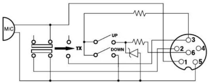
1 Modulation Modulación Modulation Modulación
2RX RX RX RX
3 TX-UP/DOWN TX-UP/DOWN TX-UP/DOWN TX-UP/DOWN
4
5 Masse Masa Ground Masa
6 Alimentation Allmentacion Power Supply Zasllanie
NORMES·F-NORMAS·F-NORMS·F-NORMY·F
| N° | Code | Frequency | FM Channel | AM Channel | Country | CH 19 | CH 9 |
| 1 | EU | 26.965 ~ 27.405 | 40 Ch (4W) | 40 Ch (4W) | AT, BE, BG, CH, CY, DK, EE, ES, FI, FR, GR, HR, HU, IE, IS, IT, LT, LU, LV, NL, NO, PT, RO, SE, SI | AM | AM |
| 2 | PL | 26.960 ~ 27.400 | -5 KHz 40 Ch (4W) | -5 KHz 40 Ch (4W) | PL | AM | AM |
| 3 | d | 26.565 ~ 27.405 | 80 Ch (4W) | 40 Ch (4W) | CZ, DE, SK | FM | AM |
| 4 | EC | 26.965 ~ 27.405 | 40 Ch (4W) | - | MT | FM | FM |
| 5 | U | 26.965 ~ 27.405 | 40 Ch (4W) | 40 Ch (4W) | UK | FM | FM |
| 27.60125 ~ 27.99125 | ENG 40 Ch (4W) | - | FM | FM | |||
| 6 | in | 26.965 ~ 27.275 | 27 Ch (4W) | 27 Ch (4W) | IN | AM | AM |
Remarque : Dans la configuration U : Pour selectionner la bande de fréquences ENG, appuyer plusieurs fois sur la touche MODE (13) jusqu'à ce que «UK» apparaissée dans l'afficheur. Pour selectionner la bande de fréquences CEPT, appuyer plusieurs fois sur la touche MODE (13) jusqu'à ce que «UK» disparaisse de l'afficheur (voir tableau page 57).
Observacion: En la configuracion U: Para selectionar la banda de fecuencia ENG, apriete varias varces la tecla MODE (13) hasta que "UK" aparezca en la pantalla. Para seleccionar la banda de fecuencia CEPT, apriete varias varces la tecla MODE (13) hasta que "UK" desaparezca de la pantalla (vease cuadro pagina 57).
Note: In U configuration: In order to select the frequency band ENG, press several times MODE key (13) until "UK" appears in the display. In order to select the CEPT frequency band, press several times MODE key (13) until "UK" disappears from the display (see table at page 57).
Uwaga: W konfiguraci U: W celu wybrania pasma czestotliwosci ENG, nacinij kilkakrotnie klawisz MODE (13), až „UK" pojawi sie na wyswietlaczu. W celu wybrania pasma czestotliwosci CEPT, nacinij kilkakrotnie klawisz MODE (13), až „UK"zniknie z wyswietlacza (patz tabela na stronie 57).
The frequency band and the transmission power of your transceiver must correspond with the configuration authorized in the country where it is used.
Countries in which there are particular restrictions (Licence/Register)
Please see updated table on website www.president-electronics.com, page 1The CB radios" then President Radio CB and Europe.