
PS700 - Sewing machine JUKI - Free user manual and instructions
Find the device manual for free PS700 JUKI in PDF.
User questions about PS700 JUKI
0 question about this device. Answer the ones you know or ask your own.
Ask a new question about this device
Download the instructions for your Sewing machine in PDF format for free! Find your manual PS700 - JUKI and take your electronic device back in hand. On this page are published all the documents necessary for the use of your device. PS700 by JUKI.
USER MANUAL PS700 JUKI
1) 縫始めの糸ゆるめ針数
縫始めの糸ゆるめ針数が変更できます。
2) 縫終りの糸ゆるめまでの針数


1) 電源を ON します。
1) 縫始めの糸ゆるめ針数
縫始めの糸ゆるめ針数が変更できます。
2) 縫終りの糸ゆるめまでの針数
(1) 押え上げ電磁弁
natural_image
Technical line drawing of a mechanical assembly with multiple cylindrical components and mounting brackets (no text or symbols)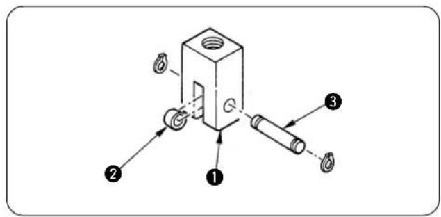

(1) 押え上げシリンダーの組み付け
(2) ミシン頭部への組付け
Ⅵ. セットアップ
1. ミシン頭部の設置
注意
natural_image
Technical diagram of a mechanical component with multiple cylindrical parts and mounting holes (no text or symbols)3) エアー配管の確認
①電源 OFF の状態で確認します。
natural_image
Technical line drawing of a mechanical assembly with an inset close-up showing internal components (no text or symbols)
natural_image
Diagram showing four sequential stages of a mechanical or robotic arm motion, with arrows indicating motion direction (no text or symbols present)natural_image
Technical line drawing of a mechanical component with multiple circular components and mounting holes (no text or symbols)(1) 縫い目
natural_image
Technical line drawing of a sewing machine with a numbered component (no text or symbols present)natural_image
Diagram of a mechanical component with threaded end and curved top surface, labeled with number ① (no text or symbols on the diagram itself)natural_image
Diagram of a mechanical or structural component with coiled spring-like elements, no text or symbols presentnatural_image
Diagram of a mechanical component with threaded end and base, labeled with number ③ (no text or symbols on the diagram itself)This Instruction Manual is intended for the LB-6.
Read and fully understand the instructions given under "IMPORTANT SAFETY INSTRUCTIONS" sin the Instruction Manual for the MO-6000△ series before putting the machine into service when this device is installed to the MO-6000△ series.
In addition, assemble and set up the device referring not only to this Instruction Manual but also to the Parts Sheet and the Instruction Manual for the SC-921 (or SC-510).
CONTENS
I. PREFACE 1
II. SETTING OF THE CONTROLLER (SC-921) 1
- Setting of the machine model....1
- Setting of the chain-off thread rolling-in function 4
- Setting of the auto-lifter function 7
- Various settings of the chain-off thread rolling-in sewing 8
- Changing procedure of the various settings 10
III. SETTING OF THE CONTROLLER (SC-510) 13
- Setting of the machine model.... 13
- Setting of the chain-off thread rolling-in function 16
- Setting of the auto-lifter function 18
- Various settings of the chain-off thread rolling-in sewing 19
- Changing procedure of the various settings 21
IV. INSTALLING THE PNEUMATIC COMPONENTS 24
- Installing the air regulator 24
- Installing the solenoid valve 25
V. INSTALLATION OF COMPONENTS TO THE SEWING MACHINE HEAD ...27
- Installing the thread tension total asm. (thread release unit) 26
- Installing the presser lifting unit 27
VI. SET-UP 29
- Installing the machine head....29
- Adjusting the synchronizer 30
- Air piping .... 31
- Connecting to the connector of the SC-921 33
- Connecting to the connector of the SC-510 34
- Installing the material end sensor 35
VII. OPERATING PROCEDURE 38
- Passing the thread....38
- Pedal operation....39
- Chain-off thread rolling-in sewing 39
- Adjusting the sewing.... 41
- Adjusting the chain-off thread rolling-in device 42
- Change-over of the chain-off thread rolling-in and the runstitching (Sensor blind)..... 43
VIII. MAINTENANCE 44
- Replacing the reflection label of the material end sensor 44
- Replacing the counter knife.... 44
- Adjusting the intermediate latch 45
IX. CORRECTIVE MEASURES FOR THE TROUBLE OF THE CHAIN-OFF THREAD ROLLING-IN SEWING 46
- In the case of using the SC-921 46
- In the case of using the SC-510 47
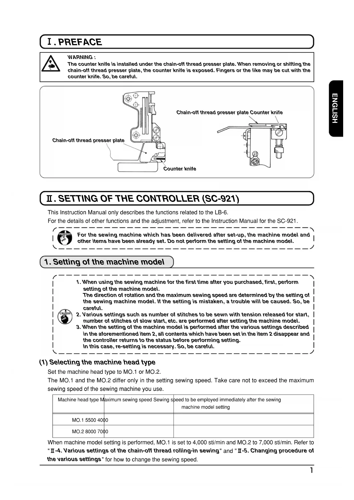
I. PREFACE

WARNING :
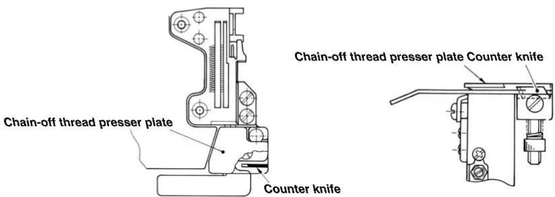
The counter knife is installed under the chain-off thread presser plate. When removing or shifting the chain-off thread presser plate, the counter knife is exposed. Fingers or the like may be cut with the counter knife. So, be careful.
II. SETTING OF THE CONTROLLER (SC-921)
This Instruction Manual only describes the functions related to the LB-6.
For the details of other functions and the adjustment, refer to the Instruction Manual for the SC-921.

For the sewing machine which has been delivered after set-up, the machine model and other items have been already set. Do not perform the setting of the machine model.
1. Setting of the machine model

- When using the sewing machine for the first time after you purchased, first, perform setting of the machine model.
The direction of rotation and the maximum sewing speed are determined by the setting of the sewing machine model. If the setting is mistaken, a trouble will be caused. So, be careful. - Various settings such as number of stitches to be sewn with tension released for start, number of stitches of slow start, etc. are performed after setting the machine model.
- When the setting of the machine model is performed after the various settings described in the aforementioned item 2, all contents which have been set in the item 2 disappear and the controller returns to the status before performing setting. In this case, re-setting is necessary. So, be careful.
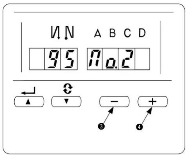
(1) Selecting the machine head type
Set the machine head type to MO.1 or MO.2.
The MO.1 and the MO.2 differ only in the setting sewing speed. Take care not to exceed the maximum sewing speed of the sewing machine you use.
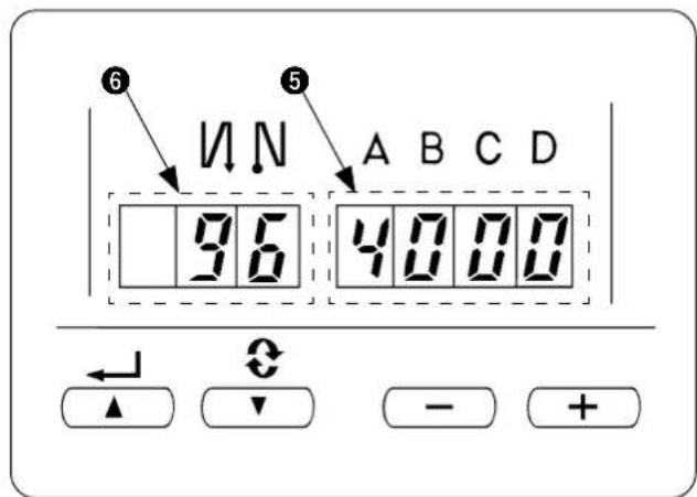
| Machine head type | Maximum sewing speed | Sewing speed to be employed immediately after the sewing machine model setting |
| MO.1 5500 4000 | ||
| MO.2 8000 7000 |
When machine model setting is performed, MO.1 is set to 4,000 sti/min and MO.2 to 7,000 sti/min. Refer to "II-4. Various settings of the chain-off thread rolling-in sewing" and "II-5. Changing procedure of the various settings" for how to change the sewing speed.
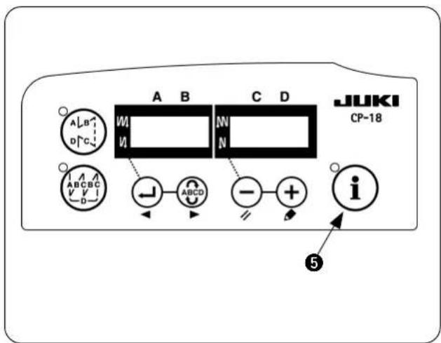
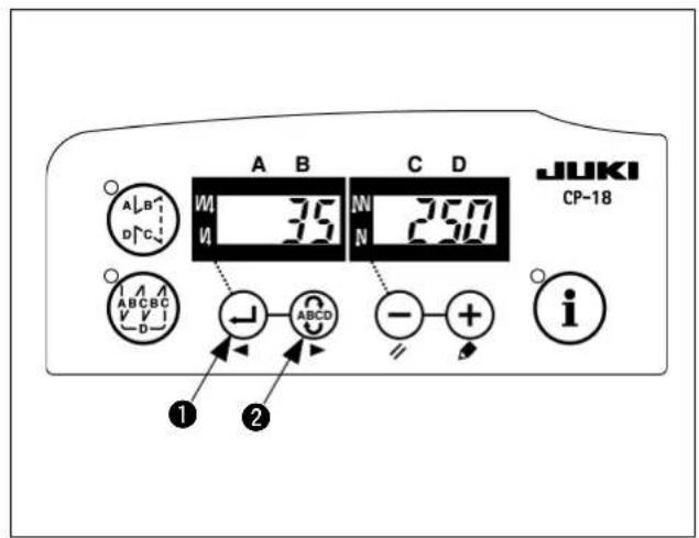
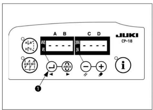
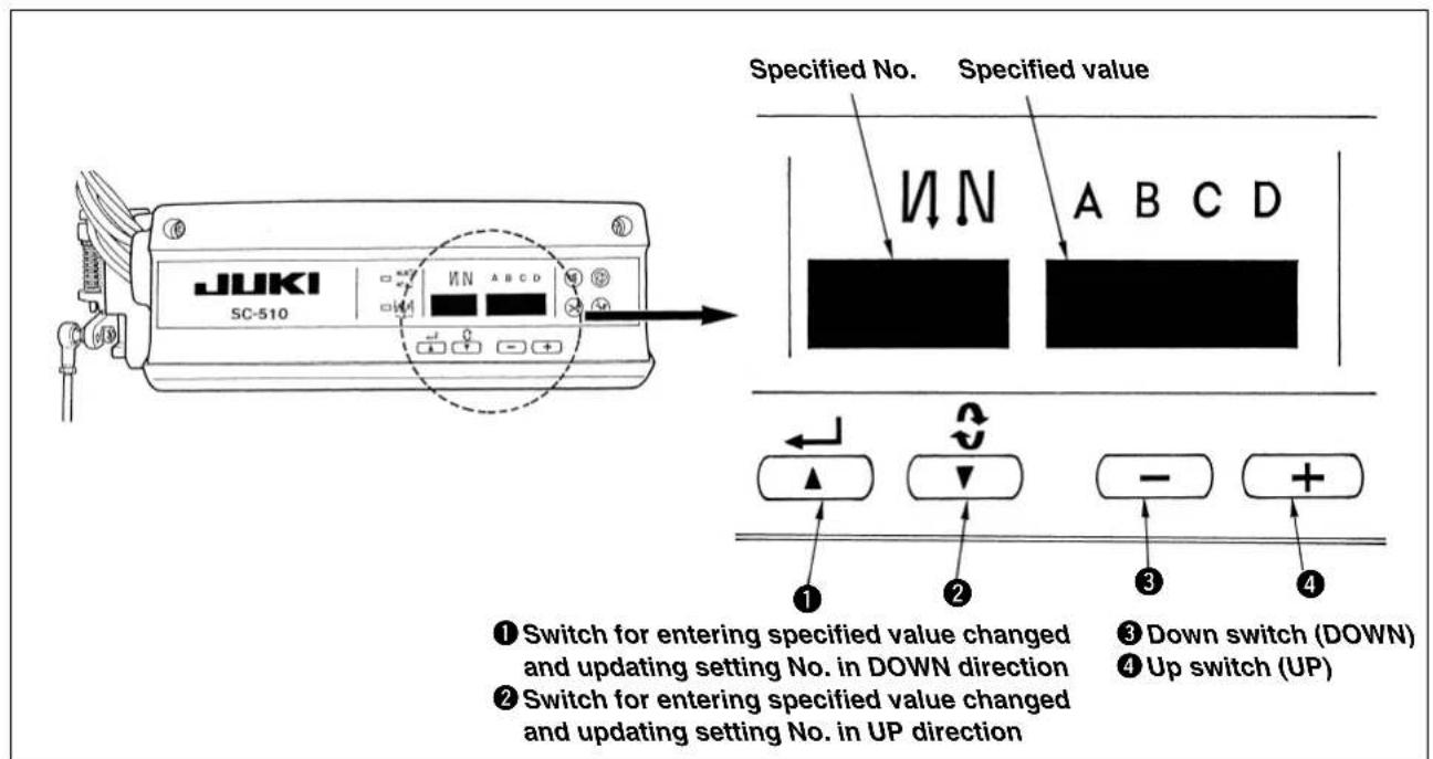
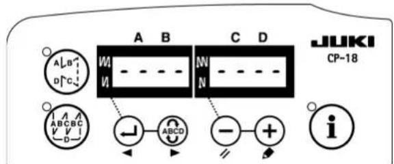
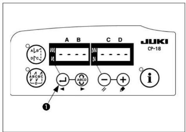
(2) Selecting procedure of the machine head type
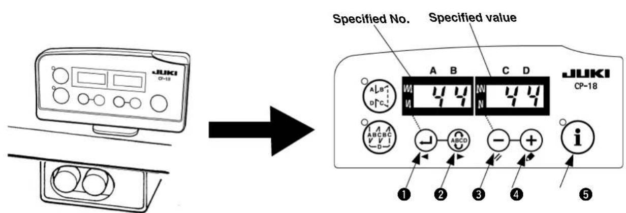
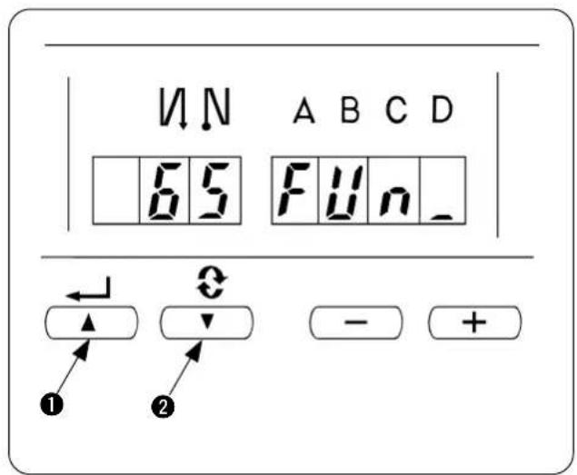
① Switch for entering specified value changed and updating setting No. in DOWN direction
② Switch for entering specified value changed and updating setting No. in UP direction
③ Down switch (DOWN)
④ Up switch (UP)
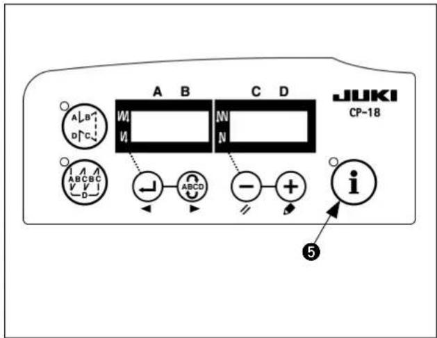
⑤ Mode changeover switch

Do not perform switch operations other than those described in the following explanations. Be sure to re-turn the power switch ON after one second or more has passed. If the power is turned ON immediately after turning it OFF, the sewing machine may not work normally. In this case, turn ON the power again.
How to change over to the function setting mode
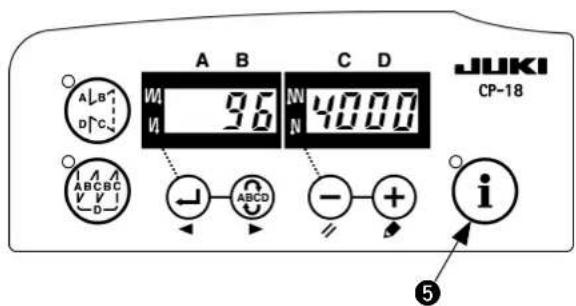
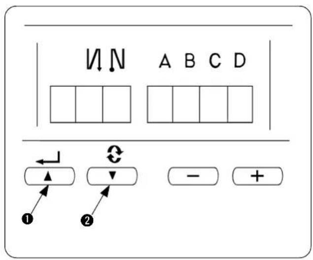
1) Turn OFF the power to the unit.
2) Pressing ⓘ switch 5, turn ON the power to the unit.
3) The display on the screen is as shown in the figure. (If the indication fails to change, re-perform the procedures 1) and 2).

If you have already set other items, the last number and the data you have set are displayed.
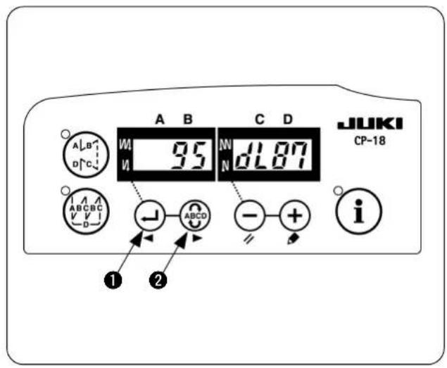
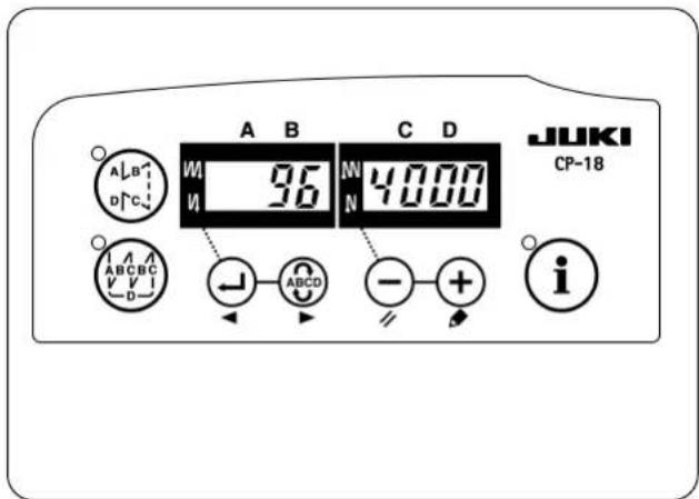
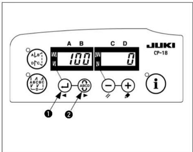
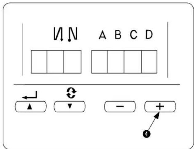
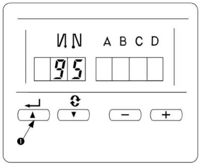
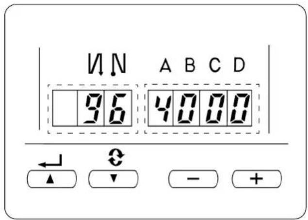
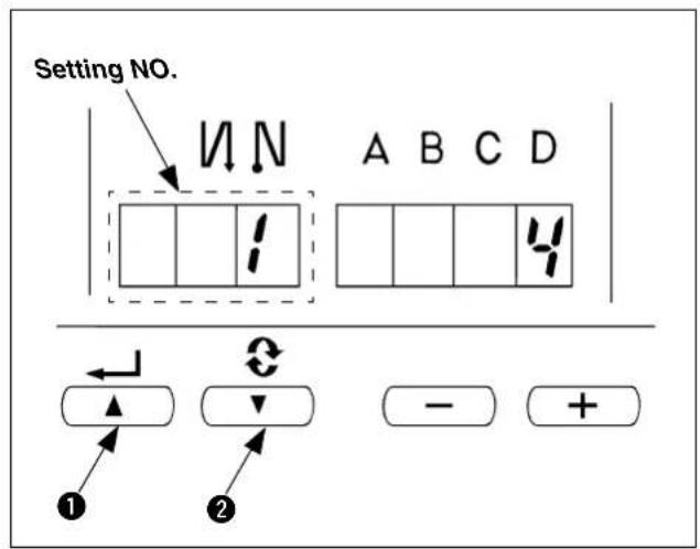
4) Press ← switch ① or ABCD switch ② to call the display as shown in the figure (No. 95).
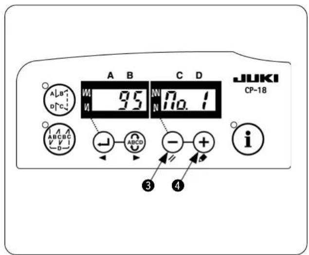
5) The type of machine head can be selected by pressing ⏻ switch ③ (⊕ switch ④). The MO.1 and the MO.2 differ only in the setting range of the maximum sewing speed.
• MO.1 : Up to 5,500 sti/min
• MO.2 : Up to 8,000 sti/min
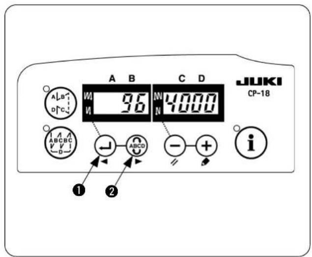
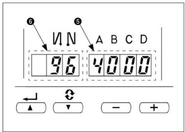
6) After selecting the type of machine head, by pressing ⏻ switch ① ( ⏻ switch ② ), the step proceeds to 96 or 94, and the display automatically changes to the contents of the setting corresponding with the type of machine head.

Turn OFF the power.

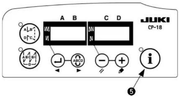
2. Setting of the chain-off thread rolling-in function
Changeover to the function setting mode [Changeover to the service mode]
1) Turn OFF the power.
2) Pressing ⓘ switch ⑤, turn ON the power.
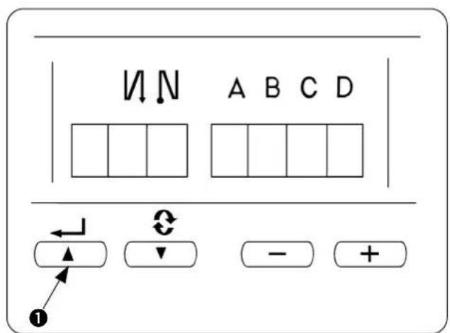
3) The screen is displayed. Continue pressing switch ⑤ for three seconds.
4) When the second buzzer beeps, the changeover to the service mode is completed.
The display of the screen is as shown in the figure. (Same as the users' mode)
![JUKI PS700 - Changeover to the function setting mode [Changeover to the service mode] - 2](/content/2026/04/592321/images/4eb7318c8148264495e90217e0832c10d69f28675630369526c46186b3b0c22d.jpg)
If you have already set other items, the last number and the data you have set are displayed.
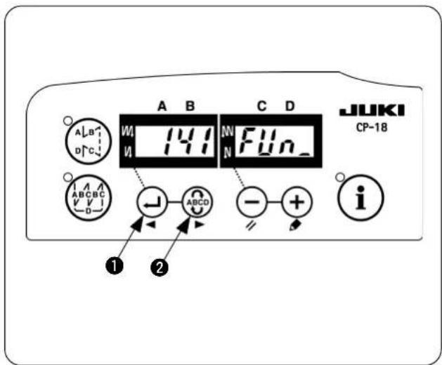
5) Call the chain-off thread rolling-in function.
Press ⏻ switch ① or ⚗ switch ② to call the display as shown in the figure (No. 141)
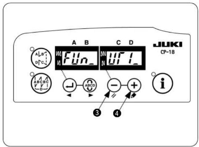
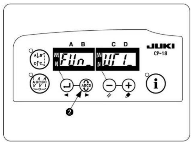
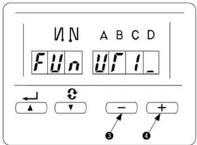
6) Press ⏻ switch ③ or ╗ switch ④ to call up the ancillary device 1. (Display of FUn_UT1_)
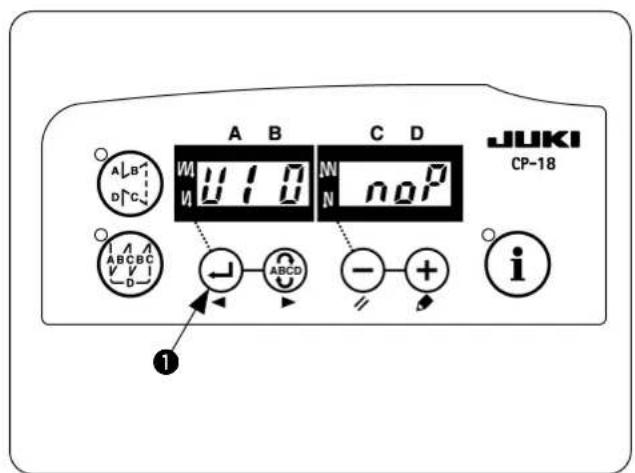
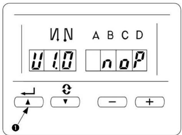
7) Press ⏻ switch ①.
(Figure is the display after pressing ⏻ switch ①.)
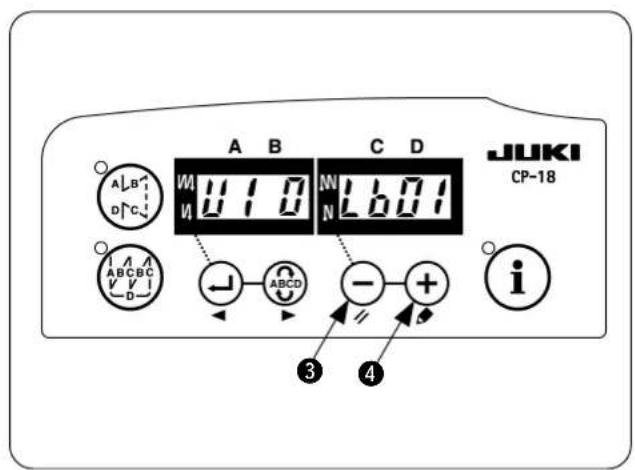
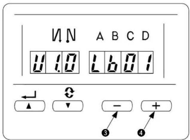
8) While "U1 0" is displayed, press switch ③ or switch ④ to call up the LB function. (Display of U1 0 Lb01)
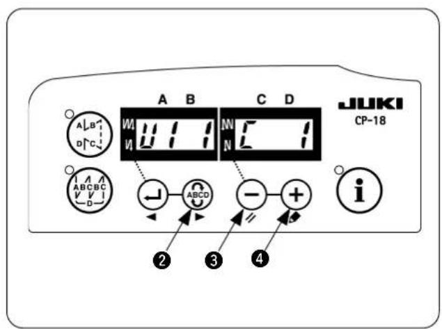
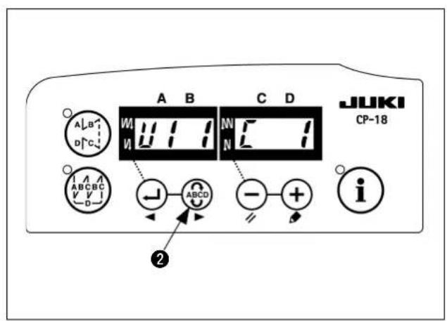
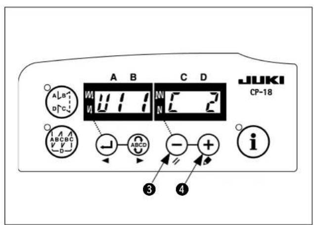
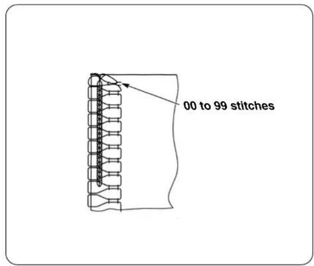
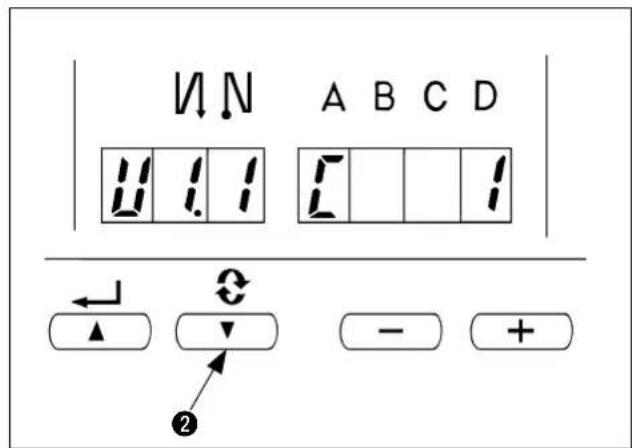
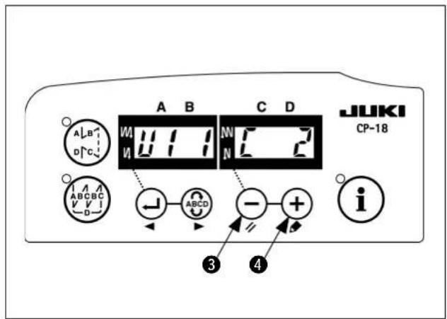
9) Press ABCD switch ② to call up "U1 1". In this state, the number of stitches to be sewn with the thread tension released at the beginning of sewing can be set. Press — switch ③ or + switch ④ to change the setting. If you do not need to change the setting, proceed to step 10).
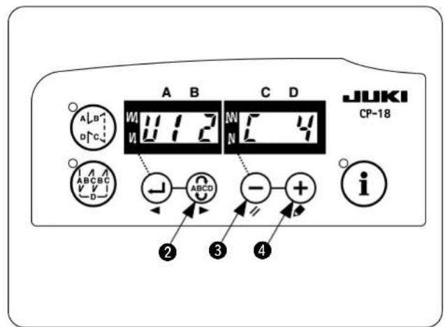
10) Press ▶ switch ② to call up "U1 2". The number of stitches to be sewing from the point at which the material sensor detects the material edge at the end of sewing to the point from which the thread tension is released. Press ⊖ switch ③ or ⊕ switch ④ to change the setting. If you do not need to change the setting, proceed to step 11).
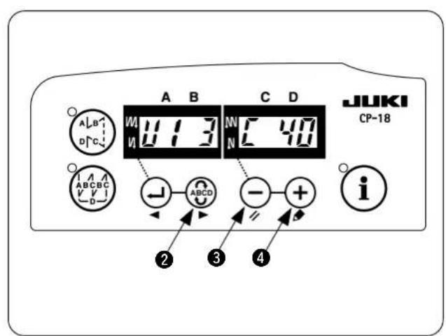
11) Press ABCD switch ② to call up "U1 3".
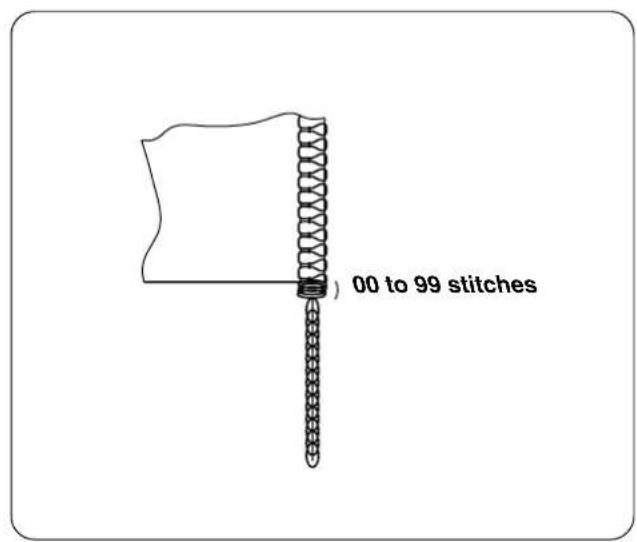
The number of chain-off stitches can be set. Press ⏻ switch ③ or ⚠ switch ④ to change the setting. If you do not need to change the setting, proceed to step 12).
12) Press ABCD switch ② to call up the display "FUn_UT1_" again. Then, turn the power off. Now, the LB function settings are confirmed.
Do not omit steps 9) to 12) even if you do not need to change the settings of "U1 1" to "U1 3". If you omit these steps, the LB function settings are not confirmed.
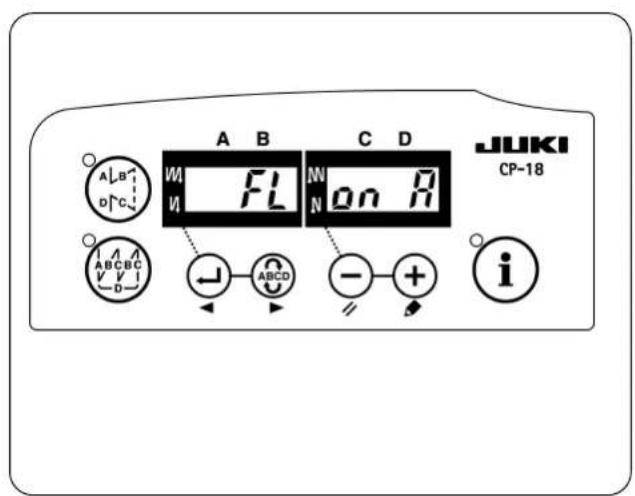
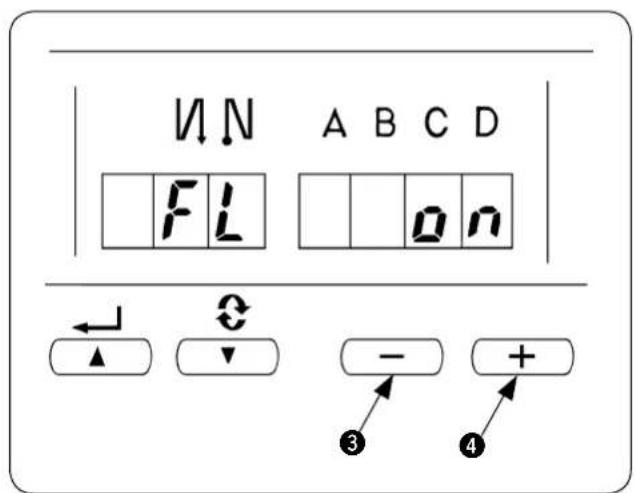
3. Setting of the auto-lifter function
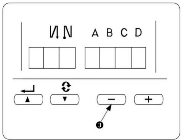
1) Turn OFF the power.
2) Pressing ⏻ switch ③, turn ON the power.
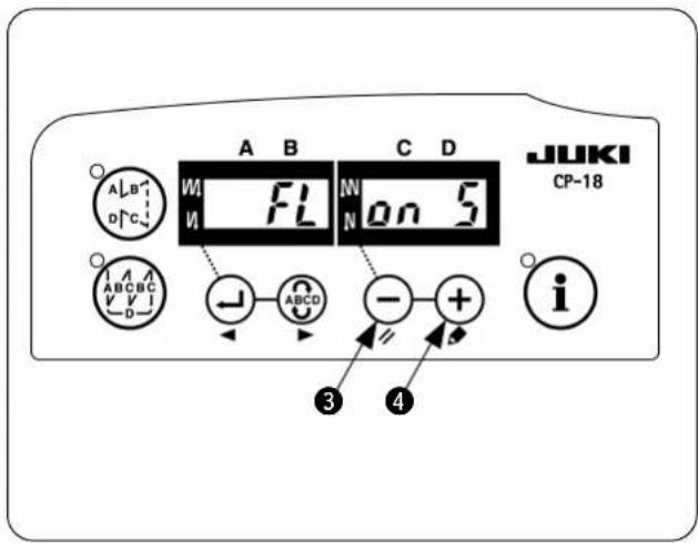
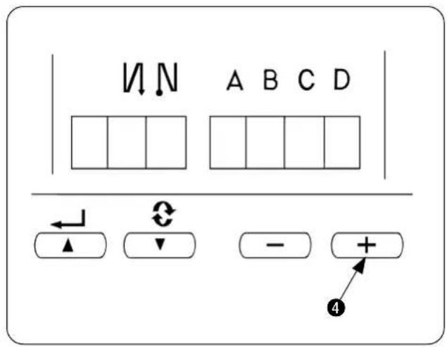
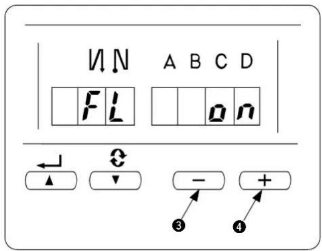
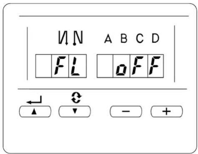
3) "FL on" is displayed. When "FL oFF" is displayed, carry out steps 1) and 2) again.
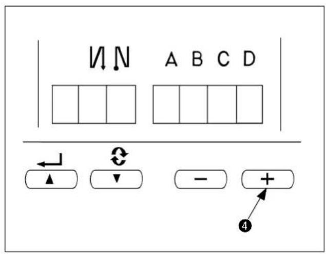
4) The display can be changed over between "FL on S" and "FL on A" by + switch ④. Select "FL on A".
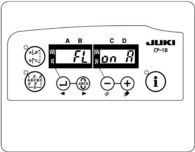
5) When the display of the screen becomes “FL on A”, the auto-lifter function becomes effective. Turn OFF the power in the state.
4. Various settings of the chain-off thread rolling-in sewing
The respective functions are set to the standard commendable values by setting of 1 through 3. However, the values can be changed in accordance with the sewing conditions. The change can be performed with “users’ mode” or “normal mode”. Typical setting item and set value as the chain-off thread rolling-in function are described in the list below.
| Setting item Standard value Setting range Change mode Program No. Remarks | |||||
| Max sewing speed [sti/min]MO.1MO.2 | 40007000 | 150 to 5500150 to 8000 | Users' mode | 96 | |
| Number of stitches of soft start [Stitch] | 4 | 0 to 19 | 1 | ||
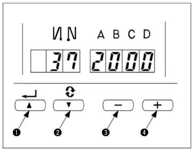
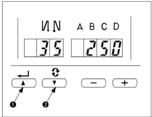
| Sewing speed for soft start [sti/min]MO.1MO.2 | 2502000 | 100 to MAX. | 37 | Max. value is that of No. 96. | |
| Chain-off thread sewing speed at the end of sewing [sti/min]MO.1MO.2 | 25003000 | 150 to MAX | 38 | Max. value is that of No. 96. | |
| Number of stitches of thread tension release at the start of sewing [Stitch] | 1 | 0 to 100 | Normal mode | U1 1 | Refer to p.8. |
| Number of stitches from detection of material end sensor at the end of sewing to thread tension release [Stitch] | 4 | 0 to 100 | U1 2 | Refer to p.8. | |
| Number of stitches of chain-off thread sewing [Stitch] | 40 | 0 to 100 | U1 3 | Length of chain-off thread is adjusted. | |
* For other setting, refer to the Instruction Manual for SC-921 and the Engineer's Manual for SC-921.

1) Number of stitches to be sewn with tension released for start
The number of stitches to be sewn with the thread tension released for the start of sewing can be changed. Chain-off thread can be neatly rolled in the seam at the start of sewing by releasing thethread tension for one or two stitches.

The number of stitches to be sewn with the tension released is the number of stitches to be sewn after start-up of the sewing machine. It is not the number of stitches to be sewn with the tension released for the actual sewing product. Be aware also that the tension releasing mechanism is incapable of starting in time depending on the settings of slow-start sewing speed and number of stitches. In such a case, the number of stitches to be sewn with the thread tension released may exceed the setting.

2) Number of stitches to be sewn with tension released for end
The number of stitches to be sewn with tension released for the end of sewing is the number of stitches to sewn after the material end comes off the material end sensor.

It is not the number of stitches to be sewn with the tension released as counted from the material end of the actual sewing product.
5. Changing procedure of the various settings
Refer to “Ⅱ-4. Various settings of the chain-off thread rolling-in sewing”, and check the change mode of the item to be changed.
Changing procedure of the respective modes is as described below.
(1) Changing procedure under the users' mode
1) Turn OFF the power.
2) Pressing ⓘ switch ⑤, turn ON the power.
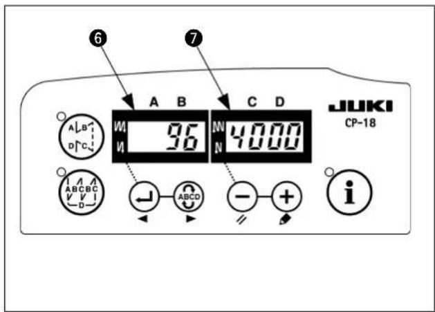
3) Indication ⑥, ⑦ will be shown on the display. (If the indication fails to change, re-perform the procedures 1) and 2).
The last number and the data you have set are displayed.
4) When you want to advance the setting No., press
switch ② to advance the setting No. When you want to return the setting No., press
switch ① to return the setting No.

When switch
① (Switch
② is held
pressing, the setting No. will return (will advance) continuously. When the setting No. is advanced (returned), the contents which are before by one (after by one) will be determined. So, be careful when changing the contents (up/down switch is touched).
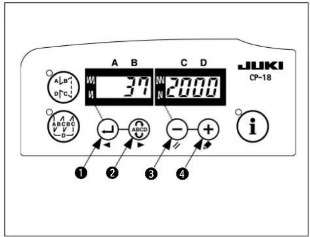
Example) Changing the soft-start sewing speed (No. 37)
Press switch
① or Switch
② to call up
No. 37. Press switch
③ or ⚙ switch
4 to
change the sewing speed.
5) When you have finished changing of the setting,
press ← switch ① or ← switch ② to confirm the value you have updated.
-
When turning OFF the power before performing this work, the contents which have been changed are not updated.
-
Press switch ①, and screen display will change to the contents of the setting No. which is before by one.
-
Press ABCD switch ②, and screen display will change to the contents of next setting No. After completing the operation, turn OFF the power and turn ON the power again to return to the normal operation.
After completing the operation, turn OFF the power and turn ON the power again to return to the normal.
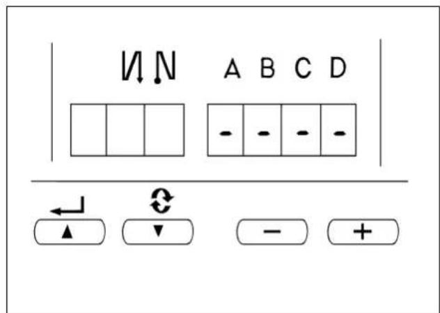
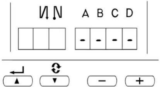
(2) Changing procedure under the normal mode
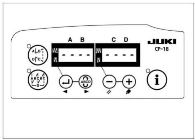
1) Turn ON the power.
Symbols of “-” are displayed under the displays of A, B, C, and D.
2) Calling of the setting mode
Press ABCD switch ②.
The display is changed over as shown in the figure, and changed over to the display of the number of stitches of each process (display C). Further press switch ② and the display is changed over to U1 1 → U1 2 → U1 3.

The sewing machine does not operate at the time of this display.
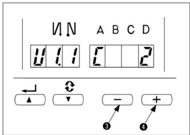
3) Press switch ③ or switch ④ to change the set value between the range of 0 and 100.
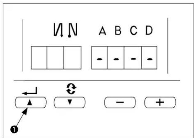
4) Determination of the contents
Press 🖼️ switch ①. The changed contents can be determined by the switch operation, and the display returns to the normal display. When the power is turned OFF on the way, the contents cannot be updated. When the display returns to the normal display, the pedal operation or the like becomes effective.
III. SETTING OF THE CONTROLLER (SC-510)
This Instruction Manual only describes the functions related to the LB-6.
For the details of other functions and the adjustment, refer to the Instruction Manual for the SC-510.

For the sewing machine which has been delivered after set-up, the machine model and other items have been already set. Do not perform the setting of the machine model.
1. Setting of the machine model

- When using the sewing machine for the first time after you purchased, first, perform setting of the machine model.
The direction of rotation and the maximum sewing speed are determined by the setting of the sewing machine model. If the setting is mistaken, a trouble will be caused. So, be careful. - Various settings such as number of stitches to be sewn with tension released for start, number of stitches of slow start, etc. are performed after setting the machine model.
- When the setting of the machine model is performed after the various settings described in the aforementioned item 2, all contents which have been set in the item 2 disappear and the controller returns to the status before performing setting. In this case, re-setting is necessary. So, be careful.
(1) Selecting the machine head type
Set the machine head type to MO.1 or MO.2.
The MO.1 and the MO.2 differ only in the setting sewing speed. Take care not to exceed the maximum sewing speed of the sewing machine you use.
| Machine head type | Maximum sewing speed | Sewing speed to be employed immediately after the sewing machine model setting |
| MO.1 5500 4000 | ||
| MO.2 8000 7000 |
When machine model setting is performed, MO.1 is set to 4,000 sti/min and MO.2 to 7,000 sti/min. Refer to "III-4. Various settings of the chain-off thread rolling-in sewing" and "III-5. Changing procedure of the various settings" for how to change the sewing speed.
(2) Selecting procedure of the machine head type

Do not perform switch operations other than those described in the following explanations. Be sure to re-turn the power switch ON after one second or more has passed. If the power is turned ON immediately after turning it OFF, the sewing machine may not work normally. In this case, turn ON the power again.
How to change over to the function setting mode [Changeover to the users' mode]
1) Turn OFF the power to the unit.
2) Pressing switch ④, turn ON the power to the unit.
3) Indication ⑤, ⑥ will be shown on the display. (If the indication fails to change, re-perform the procedures 1) and 2).
4) Press switch ① to display the figure (No. 95).
5) Press switch ③ or ④ to select the machine head type (MO.1 or MO.2).
The MO.1 and the MO.2 differ only in the setting range of the maximum sewing speed.
• MO.1 : Up to 5,500 sti/min
• MO.2 : Up to 8,000 sti/min
6) By pressing DETERMINE switch ① or ②, No. 94 or No. 96 is displayed, and setting of machine head type is determined.

Turn OFF the power.

2. Setting of the chain-off thread rolling-in function
Changeover to the function setting mode [Changeover to the service mode]
1) Turn OFF the power.
2) Pressing switch ④, turn ON the power.
3) The screen is displayed. Continue pressing switch ④ for three seconds.
4) When the second buzzer beeps, the changeover to the service mode is completed.
The display of the screen is as shown in the figure. (Same as the users' mode)
5) Call the chain-off thread rolling-in function. Press switch ① or ② to display the figure (No.65).
6) Press switch ③ or ④ to call the utility device 1. (Display of FUn UT1_)
7) By pressing switch ①, the setting is determined. (Figure is the display after pressing switch ①.)
8) Press switch ③ or ④ to call LB function. (Display of U1.0 Lb01)
9) By pressing switch ①, the setting is determined. Turn OFF the power.
3. Setting of the auto-lifter function
1) Turn OFF the power.
2) Pressing switch ③, turn ON the power.
3) When the display of the screen becomes “FL ori”, the auto-lifter function becomes effective. Turn OFF the power in the state.
* When the display of the screen appears as "FL oFF", perform again the operation of steps 1) through 3). The display changes to "FL on".
4. Various settings of the chain-off thread rolling-in sewing
The respective functions are set to the standard commendable values by setting of 1 through 3. However, the values can be changed in accordance with the sewing conditions. The change can be performed with “users’ mode” or “normal mode”. Typical setting item and set value as the chain-off thread rolling-in function are described in the list below.
| Setting item Standard value Setting range Change mode Program No. Remarks | |||||
| Max sewing speed [sti/min]MO.1MO.2 | 40007000 | 150 to 5500150 to 8000 | Users' mode | 96 | |
| Number of stitches of soft start [Stitch] | 4 | 0 to 9 | 1 | ||
| Sewing speed for soft start [sti/min]MO.1MO.2 | 2502000 | 100 to MAX. | 37 | Max. value is that of No. 96. | |
| Chain-off thread sewing speed at the end of sewing [sti/min]MO.1MO.2 | 25003000 | 150 to MAX | 38 | Max. value is that of No. 96. | |
| Number of stitches of thread tension release at the start of sewing [Stitch] | 1 | 0 to 999 | Normal mode | U1.1 | Refer to p.8. |
| Number of stitches from detection of material end sensor at the end of sewing to thread tension release [Stitch] | 4 | 0 to 999 | U1.2 | Refer to p.8. | |
| Number of stitches of chain-off thread sewing [Stitch] | 40 | 0 to 999 | U1.3 | Length of chain-off thread is adjusted. | |
* For other setting, refer to the Instruction Manual for SC-510 and the Engineer's Manual for SC-510.
1) Number of stitches to be sewn with tension released for start The number of stitches to be sewn with the thread tension released for the start of sewing can be changed. Chain-off thread can be neatly rolled in the seam at the start of sewing by releasing thethread tension for one or two stitches.

The number of stitches to be sewn with the tension released is the number of stitches to be sewn after start-up of the sewing machine. It is not the number of stitches to be sewn with the tension released for the actual sewing product. Be aware also that the tension releasing mechanism is incapable of starting in time depending on the settings of slow-start sewing speed and number of stitches. In such a case, the number of stitches to be sewn with the thread tension released may exceed the setting.
2) Number of stitches to be sewn with tension released for end The number of stitches to be sewn with tension released for the end of sewing is the number of stitches to sewn after the material end comes off the material end sensor.

It is not the number of stitches to be sewn with the tension released as counted from the material end of the actual sewing product.
5. Changing procedure of the various settings
Refer to “Ⅲ-4. Various settings of the chain-off thread rolling-in sewing”, and check the change mode of the item to be changed.
Changing procedure of the respective modes is as described below.
(1) Changing procedure under the users' mode
1) Turn OFF the power.
2) Pressing switch ④, turn ON the power.
3) Indication ⑤, ⑥ will be shown on the display. (If the indication fails to change, re-perform the procedures 1) and 2).
4) When you want to advance the setting No., press switch ② to advance the setting No.
When you want to return the setting No., press switch ① to return the setting No.

When switch ① (switch ②) is held pressing, the setting No. will return (will advance) continuously. When the setting No. is advanced (returned), the contents which are before by one (after by one) will be determined. So, be careful when changing the contents (up/down switch is touched).
Example) Change of the number of revolution of soft start
Press switch ① or ② to call No. 37.
Press switch ③ or ④ to change the number of revolution.
5) When the change has been completed, press switch ① or ② to specify the changed value.

-
When turning OFF the power before performing this work, the contents which have been changed are not updated.
-
Press switch ①, and screen display will change to the contents of the setting No. which is before by one.
-
Press switch ②, and screen display will change to the contents of next setting No. After completing the operation, turn OFF the power and turn ON the power again to return to the normal operation.
After completing the operation, turn OFF the power and turn ON the power again to return to the normal.
(2) Changing procedure under the normal mode
1) Turn ON the power.
Symbols of “-” are displayed under the displays of A, B, C, and D.
2) Calling of the setting mode
Press switch ②.
The display is changed over as shown in the figure, and changed over to the display of the number of stitches of each process (display C). Further press switch ② and the display is changed over to U1.1 → U1.2 → U1.3.

The sewing machine does not operate at the time of this display.
3) Change of the set value
Press switch ③ or ④ to change the set value between 0 to 999.
4) Determination of the contents
Press switch ①. The changed contents can be determined by the switch operation, and the display returns to the normal display.
When the power is turned OFF on the way, the contents cannot be updated. When the display returns to the normal display, the pedal operation or the like becomes effective.
IV. INSTALLING THE PNEUMATIC COMPONENTS
When assembling the pneumatic components, it is effective to prevent air leak by winding the seal tape on the screw portion of the joint or the like.
1. Installing the air regulator

WARNING :
To protect against personal injury due to abrupt start of the machine, conduct maintenance works with the power turned off.
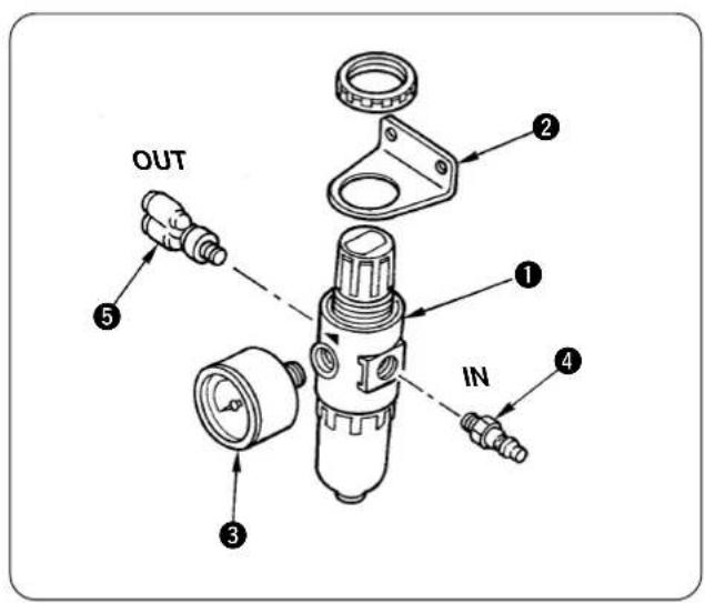
1) Attach mounting base ②, gauge ③, and joints ④ and ⑤ to air regulator ①.
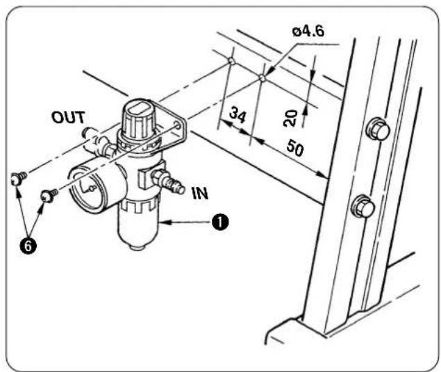
2) Drill two holes of 4.6 in the side strut of the stand, and install air regulator ① using tapping screws ⑥.
2. Installing the solenoid valve

WARNING :
To protect against personal injury due to abrupt start of the machine, conduct maintenance works with the power turned off.
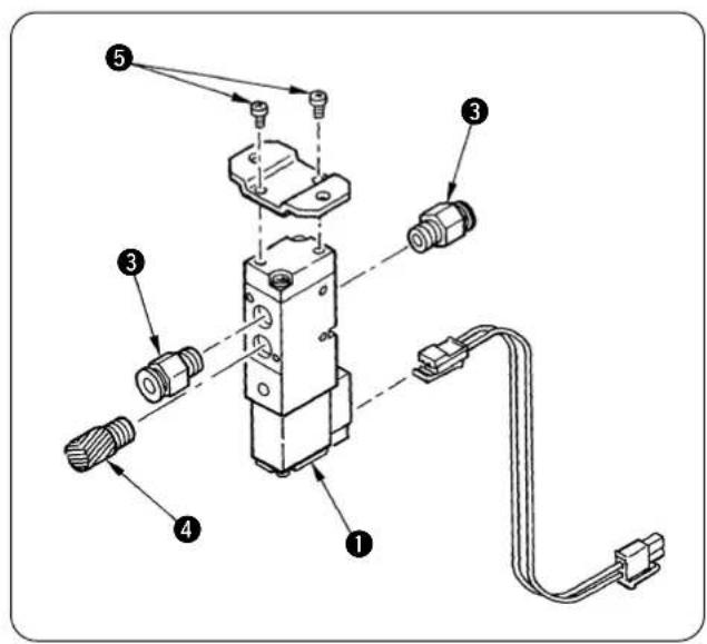
(1) Presser lifter solenoid valve
1) Attach mounting base ② to solenoid valve ① with screws ⑤.
2) 6 Attach joint ③ and silencer ④.
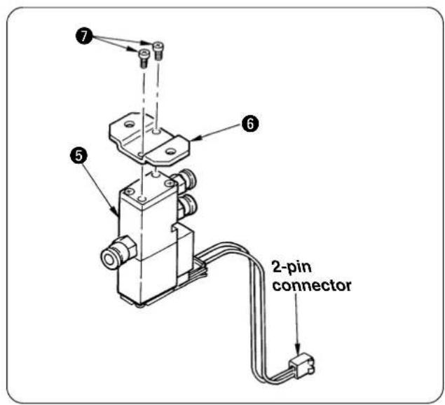
(2) Thread tension release solenoid valve
Attach mounting base ⑥ to solenoid valve ⑤ with screws ⑦.
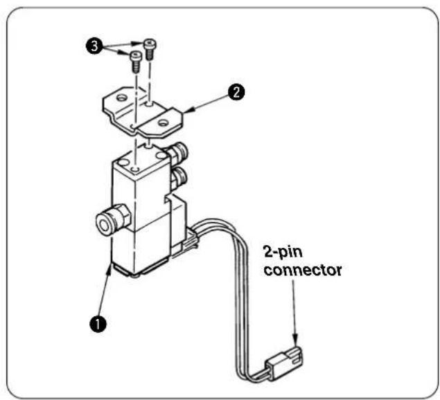
(3) Intermediate latch drive solenoid valve
Attach mounting base ② to solenoid valve ① with screws ③.
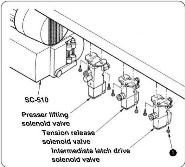
(4) Installing the various solenoid valves on the machine table
Fix the solenoid valves near the side of the motor located on the rear face of the table with wood screws ①.
V. INSTALLATION OF COMPONENTS TO THE SEWING MACHINE HEAD
1. Installing the thread tension total asm. (thread release unit)

WARNING :
To protect against personal injury due to abrupt start of the machine, conduct maintenance works with the power turned off.
natural_image
Technical line drawing of a mechanical assembly with multiple cylindrical components and mounting brackets (no text or symbols)Remove once the thread tension attached to the sewing machine and install the thread tension total asm. on the upper cover.
2. Installing the presser lifting unit

WARNING :
To protect against personal injury due to abrupt start of the machine, conduct maintenance works with the power turned off.
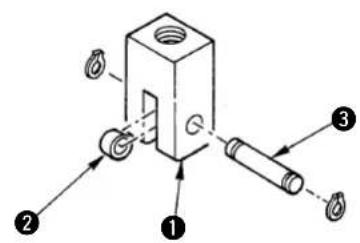
(1) Installing the presser lifting cylinder
1) Attach roller ② and pin ③ to cylinder knuckle ① and fix pin ③ with two C rings.
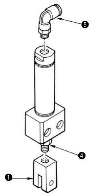
2) Screw in cylinder knuckle ① to the top end of the cylinder rod.
3) The position of cylinder knuckle ① is adjusted after installing the cylinder on the machine head. So, place it in an appropriate position. Do not fix lock nut ④ here.
4) Assemble presser lifting cylinder couple ⑤.
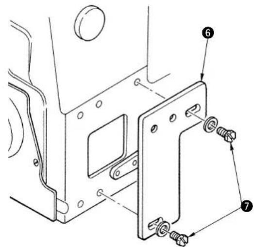
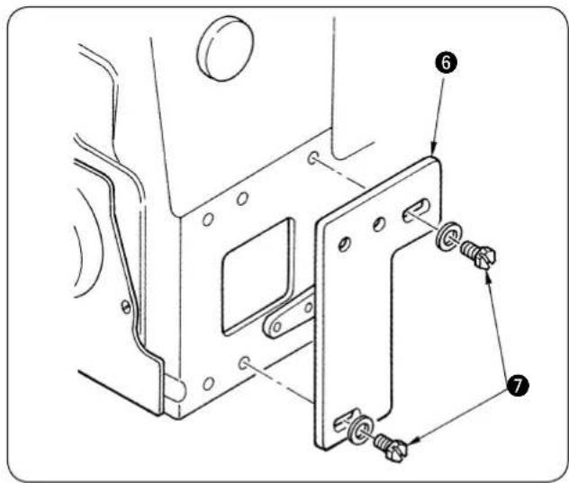
(2) Installing components to the machine head
1) Fix presser lifting cylinder mounting base ⑥ in the center of the slot with screws ⑦.
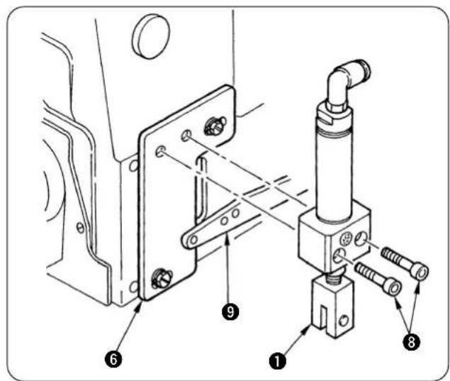
2) Install the cylinder to cylinder mounting base ⑥ with screws ⑧. At this time, assemble presser lifting lever ⑨ so that it fits in the forked portion of cylinder knuckle ⑪.
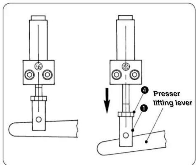
(3) Adjusting the presser lifting unit
1) Adjust the position of cylinder knuckle ①. Adjust the position so that there is a play in the lower direction of the presser lifting lever when the air cylinder shrinks and the lift amount of presser foot is secured when the air cylinder stretches. 2) When the position is determined, fix cylinder knuckle ① with lock nut ④.
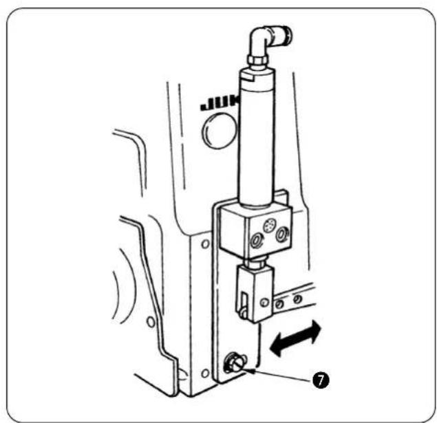
natural_image
Mechanical assembly diagram showing a valve mechanism with directional arrows (no text or symbols)3) When it is not possible to adjust the unit by means of the position of cylinder knuckle ① only, loosen screw ⑦ and move presser lifting cylinder mounting base ⑥ within the range of the slot to adjust the unit.
VI. SET-UP
1. Installing the machine head

WARNING :
To protect against personal injury due to abrupt start of the machine, conduct maintenance works with the power turned off.
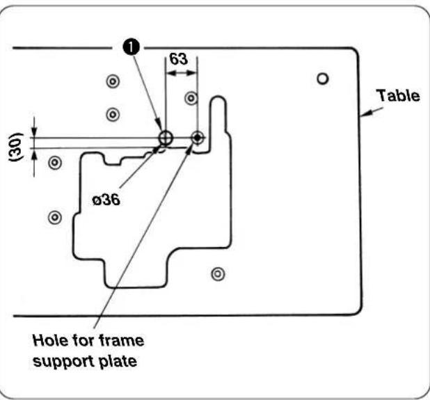
(1) Additional machining of the table
When you use a table other than JUKI Part No. 11959707, drill a hole ① for clamping cords.
(2) Place the machine head on the frame support plate and put the belt in position.
Adjust the belt tension referring to the Instruction Manual for the SC-921 (or SC-510).
(When the sewing machine is operated and the deflection of the belt is excessive, check again the belt tension.)
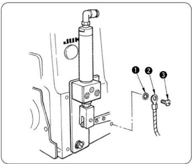
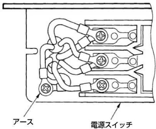
(3) Attach earth cord ②.
1) Sewing machine side
Earth mark ⏚ is attached in the rear side of the sewing machine. Attach the earth cord to the screw hole in the order of toothed lock washer ①, earth cord ② and setscrew ③.
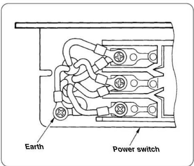
2) Power switch box side
Connect the terminal located on the opposite side of the earth cord attached to the machine head to the earth of the power switch box.
Pass the earth cord through the place where it does not come in contact with the sewing machine belt.

Perform the work with the power receptacle removed.
Open the cover of the power switch and connect the earth cord to the earth on the secondary side.
2. Adjusting the synchronizer
(1) Adjusting procedure with the built-in synchronizer

Perform the work with the power OFF except when checking the stop position.
[Needle-up position]
1) Turn the handwheel by hand to bring the needle bar to its lower dead point position.
2) Keep the hands off the sewing machine and turn ON the power in the state that it is safe even when the sewing machine starts.
The sewing machine stops after about a half rotation. This position is the up-stop position of the sewing machine.
3) Adjust the position so that the up-stop position is in the left travel end of the upper looper.
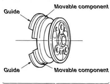
[Needle-down position]
The standard position of DOWN stop position is the state that the guide section is adjusted to the movable section.
[Adjusting procedure]
1) Remove the hand pulley.
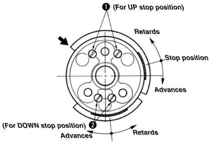
2) Loosen setscrews ① or ② and turn the movable section clockwise to advance the stop position.
After the adjustment, securely tighten the setscrews.
(Setscrews ① : for UP stop position, setscrews ② : for DOWN stop position)
3) When the adjustment is completed, attach the hand pulley and the belt cover.
For adjusting the needle-up stop position
For adjusting the needle-down stop position
(2) Installing the belt cover
Bore a hole in the belt cover through which a cord is to be passed.
Cut this section with a pair of pliers or the like.
(If the section has burrs, shave them off.)
Pass the sensor cord through the hole.
- Attach the belt cover to the table and put the belt in position. Then, put the belt cover onto the belt.
3. Air piping

WARNING : To protect against personal injury due to abrupt start of the machine, conduct maintenance works with the power turned off.
(1) Air piping drawing
Perform the piping while referring to the piping drawing below.
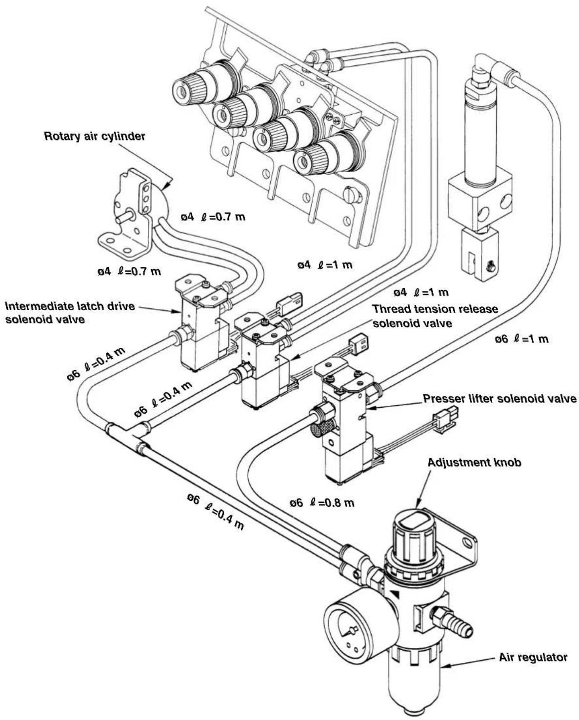
(2) Binding the air tubes and cords
Bind the air tubes and cords with the spiral tubes and cable clip bands so that they do not interfere with the moving parts such as V belt, motor, presser lifting lever, etc.
(3) Connecting the air source
1) Connect the air source with the adjustment knob of the air regulator with loosened.

Setting of the air pressure is excessive, damage will be given to the air cylinder or the like.
2) Adjusting the air regulator
Set the pressure to 0.5 MPa.
Tighten the adjustment knob of the air regulator to adjust the pressure.

natural_image
Technical diagram of a mechanical assembly with multiple cylindrical components and mounting brackets (no text or labels)3) Confirming the air piping
①Confirm the piping with the power OFF.
②Confirm that thread tension release plate ① fits in the upper thread tension disks.
natural_image
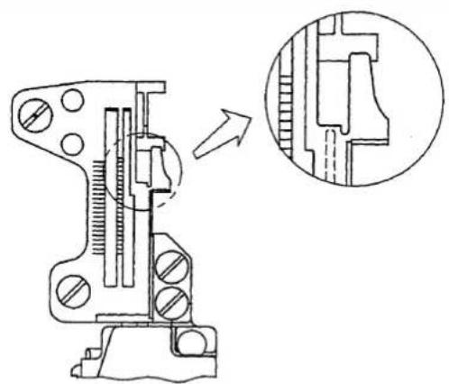
Technical line drawing of a mechanical component with an inset close-up showing internal structure (no text or symbols)③Confirm that the intermediate latch recedes in the throat plate.

If the reverse state of the description in the Instruction Manual occurs, expel the air once and change the connection of the air tube.
4. Connecting to the connector of the SC-921

WARNING :
• To prevent personal injury caused by abrupt start of the sewing machine, carry out the work after turning OFF the power switch and a lapse of 5 minutes or more.
• To prevent damage of device caused by maloperation and wrong specifications, be sure to connect all the corresponding connectors to the specified places.
• To prevent personal injury caused by maloperation, be sure to lock the connector with lock.
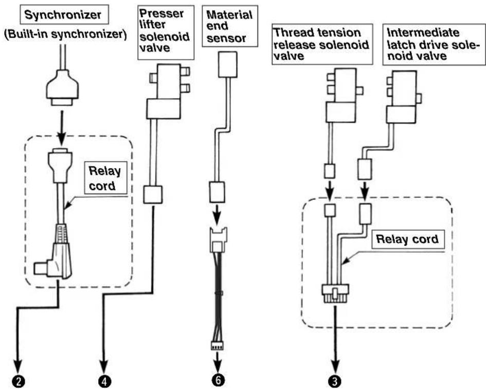
* Three kinds of relay cords (connector change cord) are used.
flowchart
graph TD
    A["Synchronizer (Built-in synchronizer)"] --> B["Component 2"]
    B --> C["Relay cord"]
    C --> D["Component 4"]
    D --> E["Component 6"]
    F["Presser lifter solenoid valve"] --> G["Component 6"]
    H["Material end sensor"] --> I["Component 6"]
    J["Thread tension release solenoid valve"] --> K["Component 3"]
    L["Intermediate latch drive solenoid valve"] --> M["Component 3"]
    N["Relay cord"] --> O["Component 3"]
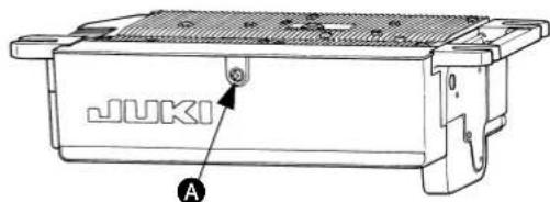
Loosen fixing screw A in the under-cover of the SC-921. Then, open the cover to find the following connectors. Connect the machine head connector to the relevant location.
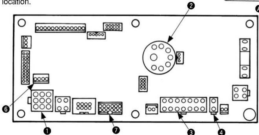

① CN30 : Connect motor signal connector.
② CN33 : Connect synchronizer.
③ CN36 : Connect intermediate latch and thread tension release solenoid valves.
④ CN37 : Connect presser lifter solenoid valve.
⑥ CN54 : Connect material end sensor.
⑦ CN39 : Connect when using foot pedal for standing work (PK-70 or the like).
5. Connecting to the connector of the SC-510

WARNING :
• To prevent personal injury caused by abrupt start of the sewing machine, carry out the work after turning OFF the power switch and a lapse of 5 minutes or more.
• To prevent damage of device caused by maloperation and wrong specifications, be sure to connect all the corresponding connectors to the specified places.
• To prevent personal injury caused by maloperation, be sure to lock the connector with lock.
* Two kinds of relay cords (connector change cord) are used.
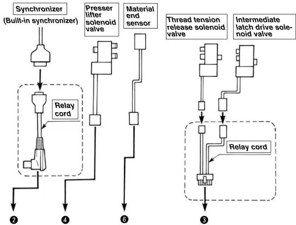
flowchart
graph TD
    A["Synchronizer (Built-in synchronizer)"] --> B["Component 2"]
    B --> C["Relay cord"]
    C --> D["Component 4"]
    D --> E["Component 6"]
    F["Presser lifter solenoid valve"] --> G["Component 6"]
    H["Material end sensor"] --> I["Component 6"]
    J["Thread tension release solenoid valve"] --> K["Component 3"]
    L["Intermediate latch drive solenoid valve"] --> M["Component 3"]
    N["Relay cord"] --> O["Component 3"]
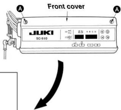
When front cover fixing screws Ⓐ of SC-510 are loosened and the cover is opened, the connectors described below are prepared. Connect the machine head connectors to the corresponding positions.
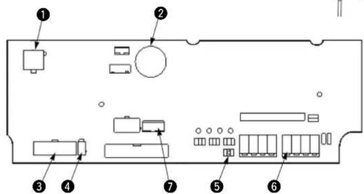
① CN30 : Connect motor signal connector.
② CN33 : Connect synchronizer.
③ CN36 : Connect intermediate latch and thread tension release solenoid valves.
④ CN37 : Connect presser lifter solenoid valve.
⑤ W4 : Jumper pin for material end sensor input/output power changeover (Change to +12V. Refer to the next page.)
⑥ CN51 : Connect material end sensor.
⑦ CN39 : Connect when using foot pedal for standing work (PK-70 or the like).
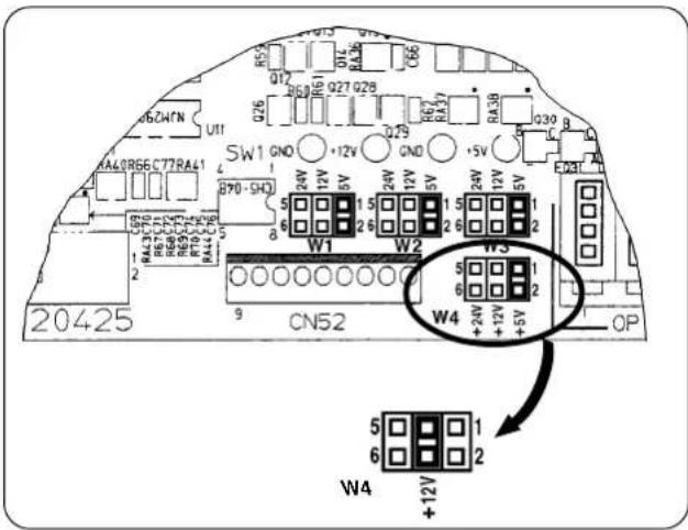
Change the jumper pin for material end sensor from +5V to +12V.
(+5V has been set at the time of delivery from the factory.)

The material end sensor does not operate properly unless this setting is performed.
6. Installing the material end sensor

WARNING :
To protect against personal injury due to abrupt start of the machine, conduct maintenance works with the power turned off.
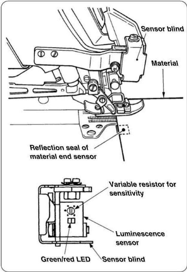
(1) Installing the components
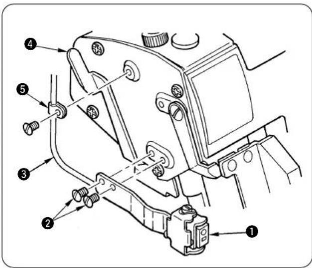
1) Install luminescence sensor ① with screws ② so that it is in parallel to the cloth plate.
2) Fix the sensor cord ③ with cord clamp ⑤ so that it is not caught with presser lifting lever ④.
(2) Connection to the control box
1) Pass the cord of luminescence sensor to the round hole of the table located in the rear side of the sewing machine.
For connecting to the SC-921, refer to "VI-4. Connecting to the connector of the SC-921".
For connecting to the SC-510, refer to "VI-5. Connecting to the connector of the SC-510".
(3) Pasting the reflection label

WARNING :
Do not depress the starting pedal since there is the danger of abrupt rotation of the sewing machine.
To avoid the maloperation, it is recommended to perform the work without putting the V belt.
1) Pasting the reflection label
Wipe out dirt or oil from the top surface of the pasting portion beforehand.
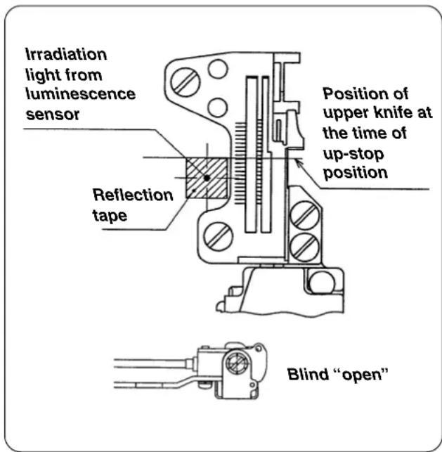
2) Pasting position of the reflection label :
(Longitudinal direction)
Paste the seal making the upper knife as reference.
(Lateral direction)
Turn ON the power to the sewing machine and paste it in the position where the red light of the luminescence sensor is irradiated.
3) When the irradiation position of the red light of the luminescence sensor does not match the position of the reflection label which has been pasted in the longitudinal direction, adjust the installing position of the material end sensor asm.

Perform the work with the sensor blind "open".
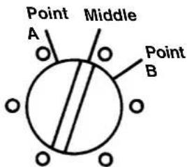
(4) Adjusting the sensitivity of the luminescence sensor

WARNING :
Do not depress the starting pedal since there is the danger of abrupt rotation of the sewing machine. To avoid the maloperation, it is recommended to perform the work without putting the V belt.
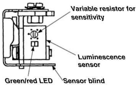
1) Adjust the sensitivity with the variable resistor for the sensitivity adjustment of the luminescence sensor as described below.
Without material : Green and red light up.
With material : Green lights up and red goes off.
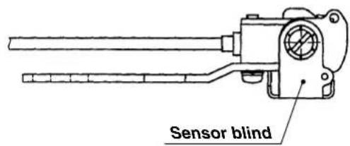
* Sensor blind is in the state of "open" as shown in the figure on the left.
2) Adjust the sensitivity of the luminescence sensor in accordance with the material to be sewn.
natural_image
Technical line drawing of a mechanical assembly with bolts and a handle (no text or symbols)[Adjusting procedure]
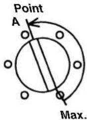
1) State without material on the sensor
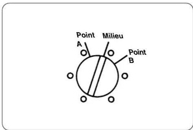
Turn the variable resistor for the sensitivity adjustment from the maximum position gradually toward the direction in which the sensitivity is decreased until the stable indicator lamp (green LED) goes out. This position is designated as point A.
![JUKI PS700 - [Adjusting procedure] - 1](/content/2026/04/592321/images/e82a8f9d9f1fe120be3e992a9a0ddf35460b0ac7eb13c64babc44a2d92da3adb.jpg)
![JUKI PS700 - [Adjusting procedure] - 2](/content/2026/04/592321/images/21f2340e8d518fbf56969f544f7862078381ffbe2dc0339886bc8aed6cce0364.jpg)
natural_image
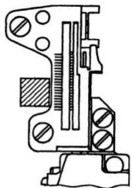
Technical line drawing of a mechanical component with crosshair indicators (no text or symbols)2) State with material on the sensor
Place the material to be sewn on the sensor mounted on the cloth plate. Turn the variable resistor for the sensitivity adjustment from point A gradually toward the direction in which the sensitivity is increased until the stable indicator lamp (green LED) goes out. This position is designated as point B.
3) Set the variable resistor for the sensitivity adjustment to the middle of points A and B.
4) Confirmation
Confirm the followings :
When material is not placed on the sensor : Green and red light up.
When material is placed on the sensor : Green lights up and red goes out.
The sensitivity adjustment of the material end sensor has been completed.
VII. OPERATING PROCEDURE
Check the following items so as to avoid malfunction/damage of/to the machine.
- Clean up the machine before putting the machine into service for the first time after the set-up.
- Remove dust accumulated on the machine during transportation and lubricate it.
- Check to be sure that the voltage is set to a correct value.
- Check to be sure that the power plug is properly connected.
- Never use the machine with any voltage specification different from the correct one.
- Refer to the standard instruction manuals for the respective models of machines for lubrication, installation of the needle, adjustment of presser foot pressure, removing the presser foot, adjustment of stitch length, adjustment of differential feed, adjustment of knife and overedging width, cleaning of the machine head, and cleaning and replacement of filter and pump net.
1. Passing the thread

WARNING :
To protect against personal injury due to abrupt start of the machine, conduct maintenance works with the power turned off.
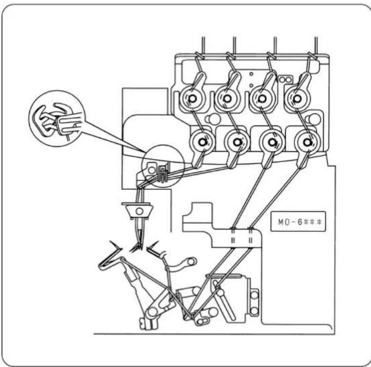
Thread the machine head as illustrated.
(A threading diagram is adhered also in the rear side of the looper cover.)
2. Pedal operation

WARNING :
To prevent possible injury caused by abrupt start of the machine, be sure to keep hands, hair and clothes away from the rotating parts and needle entry area.

When the power switch is turned on, the sewing machine will actuate to make a half to one revolution to detect the highest dead point of the machine. If you place hands, hair and clothes near the rotating parts or the needle entry area, a stab or injury resulting from being involved/caught in the aforementioned parts/area can result.
natural_image
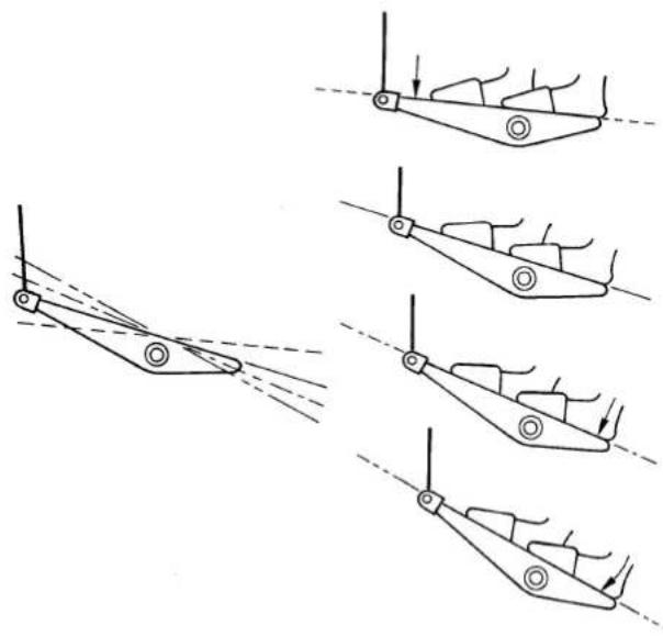
Diagram showing four sequential stages of a mechanical or robotic arm motion, with arrows indicating motion direction (no text or symbols present)① Depressing the front part of pedal --- Sewing machine runs.
② Pedal is in its neutral position.
--- Sewing machine stops.
③ Depressing the back part of pedal
--- Presser foot goes up. (Presser foot comes down.)
④ Fully depressing the back part of pedal
--- Initialization of the operation of presser lifting and chain-off thread rolling-in.
(Use at the start of sewing only. Do not perform this operation during sewing.)

Fully depressing the back part of the pedal of ④ initializes the chain-off thread rolling-in operation.
Accordingly, if the operation of 4 has been performed during sewing, "thread tension release at the start of sewing" is actuated when starting sewing again.
Do not perform the operation of ④ during sewing.
3. Chain-off thread rolling-in sewing
SC-921
SC-510
(1) Confirmation of the display of the SC-921 (or SC-510)
Check to be sure that "----" is displayed on the screen when you turn on the power to SC.
If not, re-check the setting of the SC-921 (or SC-510).
(2) Setting the material and confirming the material end sensor
1) Depress the back part of the starting pedal to lift the needle and presser foot.
2) Push the material to be sewn under the upper knife as far as it will go to set the material.
At this time, Confirm that the display of the luminescence sensor is :
With material : Green and red light up.
Without material : Green lights up and red goes out.
* Sensor blind is in the state of "open" as shown in the figure on the left side. When the starting pedal is detached, the presser foot comes down.
3) When the display of the luminescence sensor is not normal, perform “VIII-1 Replacing the reflection label of the material end sensor”, or “VI-6-(4) Adjusting the sensitivity of the luminescence sensor”.
(3) Starting
Depress the front part of the starting pedal, and the machine will start.

-
If the material does not reach the sensor, the sewing machine will not start even if you depress the starting pedal. It is therefore necessary to place the material in the predetermined position without fail.
-
To lift the presser foot during sewing, depress the back part of the starting pedal. (Do not fully depress the back part of pedal.)
(4) End of sewing
1) The chain-off thread sewing automatically starts when the material end comes off the sensor. When the sewing machine has sewn the specified number of stitches of chain-off thread sewing, the sewing machine stops and the presser foot goes up.

The sewing machine does not stop even if you release the starting pedal during the automatic chain-off thread sewing. Turn OFF the power in case of emergency.
2) For the setting of the (automatic) chain-off thread sewing speed and the number of stitches at the end of sewing, refer to "II-4. Various settings of the chain-off thread rolling-in sewing" and "II-5. Changing procedure of the various settings" in the case of the SC-921 or to "III-4. Various settings of the chain-off thread rolling-in sewing" and "III-5. Changing procedure of the various settings" in the case of the SC-510.
(5) Cutting away chain-off thread from the material
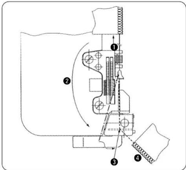
Lightly pull chain-off thread produced at the end of sewing away from you. (To such an extent that the chain-off thread comes off the latch of the throat plate)
② Route the chain-off thread so that it is not caught by the feed dog.
③ Place the chain-off thread under the chain-off thread pressing plate.
* Pull the chain-off thread toward you, and place the chain-off thread in the state of being stretched.
4 When the chain-off thread is placed further to the right direction after it has entered the groove of throat plate, the counter knife cuts away the chain-off thread from the material.
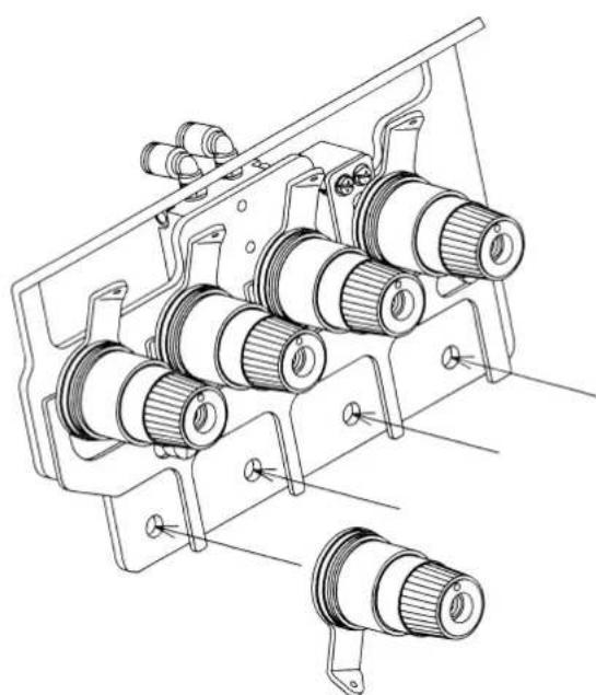
4. Adjusting the sewing
(1) Stitches
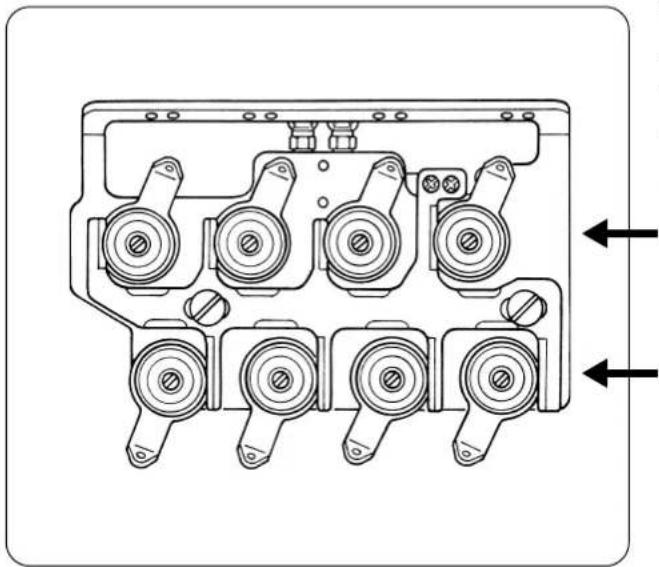
natural_image
Technical line drawing of a mechanical component with multiple circular ports and mounting brackets (no text or symbols)The thread tension controllers to adjust stitches are the ones on the lower stage of the two stages of the thread tension controllers.
The thread tension controllers on the upper stage are used for the chain-off thread sewing.
Upper stage : For chain-off thread sewing
Lower stage : For stitches
Adjust the controllers so tat the desired stitches can be obtained.
(2) Chain-off thread
The most desired state of the chain-off thread is soft-chains.
Adjust the thread with the thread tension controllers on the upper stage.
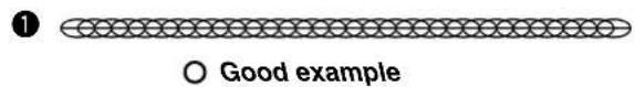
Adjust so that looper thread and needle thread interlace by the same length. ①
(Chain-off thread that slightly returns to the previous length when it is drawn then released.)
Tighten the protruding thread.
If this type of chain-off thread is produced, the needle thread may sew the chain-off thread resulting in improper rolling-in of the chain-off thread. ②
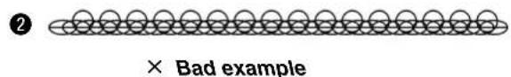
5. Adjusting the chain-off thread rolling-in device
(1) Adjusting the pressure of the chain-off thread presser spring
natural_image
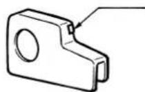
Technical line drawing of a sewing machine with mechanical components and a numbered label (1), no readable text or symbols present.Perform the adjustment with chain-off thread pressure adjusting screw ①.
natural_image
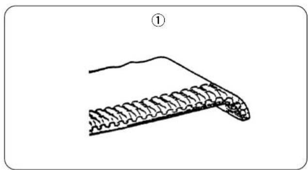
Diagram of a curved structure with layered texture, labeled with number ① (no text or symbols on the diagram itself)①Adjust the pressure of the spring to such an extent that the material end at the start of sewing is slightly rolled downward as shown in the figure ①.
natural_image
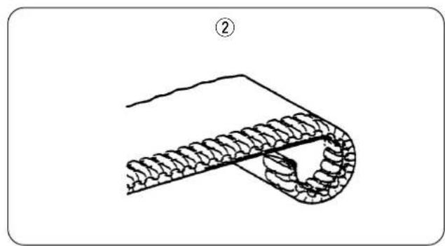
Diagram of a mechanical component with coiled spring and triangular end (no text or symbols)②Decrease the pressure of the spring when the material end at the start of sewing is excessively rolled downward.
natural_image
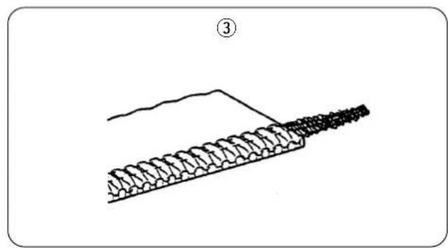
Diagram of a mechanical component with springs and a triangular load, labeled with number ③ (no text or symbols on the diagram itself)③Increase the pressure of the spring when the chain-off thread at the start of sewing does not enter the stitches and protrudes outward.
6. Change-over of the chain-off thread rolling-in and the runstitching (Sensor blind)
By opening/closing the blind of the material end sensor, the sewing machine can be used either for the chain-off thread rolling-in or for the runstitching.
Opening/closing the blind is of rotary type.
1) Blind "open"
The sewing machine can be used for the chain-off thread rolling-in.
(When the material is not placed on the sensor, the machine does not start even when depressing the front part of the starting pedal.)
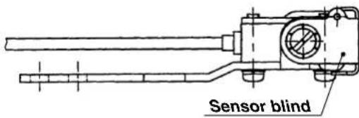
2) Blind "close"
The sewing machine can be used for the runstitching.
(Regardless of the material, the machine starts.)

In case of closing the blind of the material end sensor (runstitching), thread tension release at the start of sewing and soft start operate at the time of the first sewing after turning ON the power and sewing after fully depressing the back part of the starting pedal. It is possible to avoid the operation by setting the number of stitches of thread tension release at the start of sewing and the number of stitches of soft start to "0".
VIII. MAINTENANCE
1. Replacing the reflection label of the material end sensor

WARNING :
To protect against personal injury due to abrupt start of the machine, conduct maintenance works with the power turned off.
The reflection label is always in touch with the sewing product. This causes the surface of the label to wear to impair the reflection performance of the label. If the label has worn out, it has to be replaced with a new one. In the case where the label loses the reflection performance, the sewing machine can operate with no material placed on the machine at the start of sewing or cannot produce soft-chain type chain-off thread. In this case, the chain-off thread rolling-in function will fail to work. If the reflection performance of the label cannot be resumed by adjusting the sensor, be sure to remove the worn-out label and adhere a new one on the cloth plate.
1) Peel off the reflection label from the cloth plate.
2) Degrease the surface of the cloth plate on which the label has been adhered and adhere a new label there.

After the reflection label is replaced, adjust the sensor sensitivity.
See “V-6-(4). Adjusting the sensitivity of the luminescence sensor” for the adjusting procedure of the sensor sensitivity.
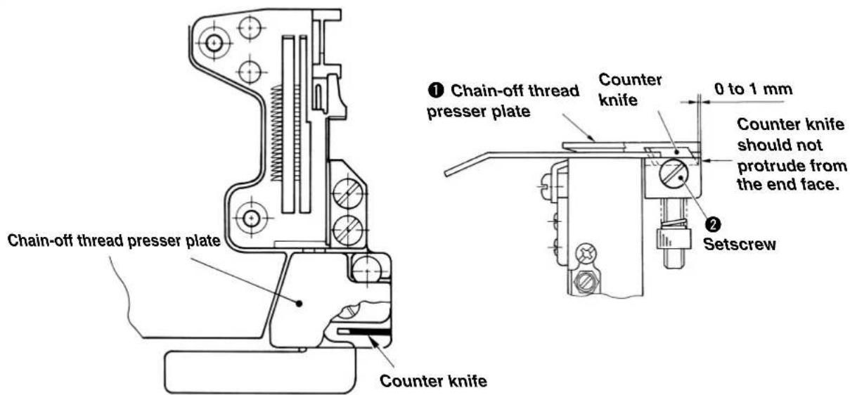
2. Replacing the counter knife

WARNING :
To protect against personal injury due to abrupt start of the machine, conduct maintenance works with the power turned off.
When the sharpness of the counter knife to cut the chain-off thread has been deteriorated, replace the counter knife.
Perform the work with care so that your finger or the like is not cut with the counter knife when replacing the knife.
1) Hold up and turn the chain-off thread presser plate ① to see the counter knife.
2) Loosen the setscrews ② and replace the counter knife.

When attaching the counter knife, attach the counter knife so that it comes in contact with the bottom face. If the chain-off thread presser rises, retaining of the chain-off thread cannot be performed well.
3. Adjusting the intermediate latch

WARNING : To protect against personal injury due to abrupt start of the machine, conduct maintenance works with the power turned off.
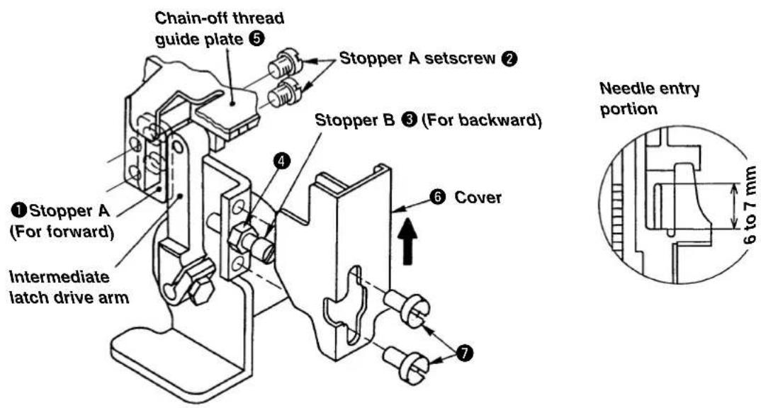
(1) Adjusting protruding amount of the intermediate latch
Actuate stopper A ① at the position where the intermediate latch protrudes 6 to 7 mm from the throat plate. At this time, assemble stopper A with setscrews ② so that it comes in contact with the plane.
(The work can be performed with ease when adjusting the protruding amount to 6 to 7 mm with stopper B ③, then make stopper A ① come in contact with the plane.)

Excessive protruding of the intermediate latch will be the cause of needle breakage. So, be careful.
(2) Adjusting receding position of the intermediate latch
Needle entry portion
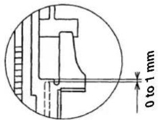
Actuate stopper B ③ at the position where the top end of intermediate latch recedes 0 to 1 mm from the throat plate. After the adjustment, fix stopper B ③ with nut ④.
(The work can be performed with ease when adjusting with stopper B ③ so that the top end of intermediate latch is flush with the throat plate, then loosen the stopper B by 1/2 to 3/4 turn.)

Excessive receding of the intermediate latch will deteriorate the movement. So, be careful.
(3) Attaching the cover
Lightly press cover ⑥ in the direction of the arrow mark, make it come in contact with chain-off guide plate ⑤ and fix it with setscrews ⑦.
IX. CORRECTIVE MEASURES FOR THE TROUBLE OF THE CHAIN-OFF THREAD ROLLING-IN SEWING
1. In the case of using the SC-921
| Items to correspond to the trouble Ref. page | |
| 1. When the chain-off thread is not neatly rolled in : | |
| 1 Making the state of soft-chains of the chain-off thread p41 | |
| 2 Increasing the pressure of chain-off thread presser spring p.42 | |
| 3 Increasing the number of stitches to be sewn with tension released for start p.8 , 12 | |
| 4 Decrease the slow-start sewing speed. p.8 , 10 | |
| 5 Increasing the number of stitches of the slow start p.8 , 10 | |
| 2. When the needle thread tension is released at the start of sewing | |
| 1 Decreasing the number of stitches to be sewn with tension released p.8 , 12 | |
| 2 Decrease the slow-start sewing speed. p.8 , 10 | |
| 3 Increasing the number of stitches of the slow start p.8 , 10 | |
 Chain-off thread can be neatly rolled in the seam at the start of sewing by releasing the thread tension for one or two stitches. Chain-off thread can be neatly rolled in the seam at the start of sewing by releasing the thread tension for one or two stitches. | |
| Other items to be checked : | |
| 1 The mode is set to the chain-off rolling-in mode ? p.8 to 12 | |
| 2 Slow start is set ? p.8 to 12 | |
| 3 Chain-off presser plate is rising ? p.44 | |
| 4 Thread tension plate normally works without friction ? p.26 , 32 | |
| 5 Material to be sewn is pushed under the upper knife as far as it will go ? p.35 | |
2. In the case of using the SC-510
| Items to correspond to the trouble Ref. page | |
| 1. When the chain-off thread is not neatly rolled in : | |
| 1 Making the state of soft-chains of the chain-off thread p.41 | |
| 2 Increasing the pressure of chain-off thread presser spring p.42 | |
| 3 Increasing the number of stitches to be sewn with tension released for start p.19 , 23 | |
| 4 Decrease the slow-start sewing speed. p.19 , 21 | |
| 5 Increasing the number of stitches of the slow start p.19 , 21 | |
| 2. When the needle thread tension is released at the start of sewing | |
| 1 Decreasing the number of stitches to be sewn with tension released p.19 , 23 | |
| 2 Decrease the slow-start sewing speed. p.19 , 21 | |
| 3 Increasing the number of stitches of the slow start p.19 , 21 | |
| [IMAGE] Chain-off thread can be neatly rolled in the seam at the start of sewing by releasing the thread tension for one or two stitches. | |
| Other items to be checked : | |
| 1 The mode is set to the chain-off rolling-in mode ? p.19 to 23 | |
| 2 Slow start is set ? p.19 to 23 | |
| 3 Chain-off presser plate is rising ? p.44 | |
| 4 Thread tension plate normally works without friction ? p.26 , 32 | |
| 5 Material to be sewn is pushed under the upper knife as far as it will go ? p.35 | |
DEUTSCH
natural_image
Technical line drawing of a mechanical assembly with multiple cylindrical components and mounting brackets (no text or symbols)natural_image
Mechanical assembly diagram showing a valve mechanism with directional arrows (no text or labels)natural_image
Technical diagram of an engine cylinder assembly with multiple crankshaft heads and mounting brackets (no text or labels)natural_image
Technical line drawing of a mechanical component with an inset close-up showing internal structure (no text or symbols)
natural_image
Technical line drawing of a mechanical assembly with bolts and a handle (no text or symbols)natural_image
Technical line drawing of a mechanical component with multiple circular ports and mounting brackets (no text or symbols)(1) Stiche
natural_image
Technical line drawing of a sewing machine component with no visible text or symbolsnatural_image
Diagram of a mechanical component with layered structure and labeled section (1), no text or symbols presentnatural_image
Diagram of a mechanical or electrical component with coiled spring and connecting rod (no text or symbols)natural_image
Diagram of a mechanical component with springs and a triangular load, labeled with number ③ (no text or symbols on the diagram itself)natural_image
Technical line drawing of a mechanical assembly with multiple cylindrical components and mounting brackets (no text or symbols)natural_image
Mechanical assembly diagram showing a valve mechanism with directional arrows (no text or symbols)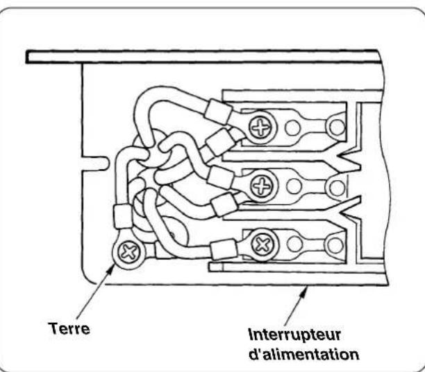
natural_image
Technical diagram of a mechanical assembly with multiple circular components and mounting holes (no text or labels)natural_image
Technical line drawing of a mechanical component with an inset close-up showing internal structure (no text or symbols)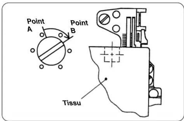
natural_image
Diagram showing four sequential stages of a mechanical linkage or suspension mechanism, with no text or symbols present.natural_image
Technical line drawing of a mechanical component with multiple circular components and mounting brackets (no text or symbols)natural_image
Technical line drawing of a sewing machine with mechanical components and a numbered label (1), no readable text or symbols present.natural_image
Diagram of a mechanical component with a curved base and threaded end, labeled with number ① (no text or symbols on the diagram itself)natural_image
Diagram of a mechanical or electrical component with coiled spring and connecting rod (no text or symbols)natural_image
Diagram of a mechanical component with a spring-like structure and a triangular load, labeled with number ③ (no text or symbols on the diagram itself)natural_image
Technical line drawing of a mechanical assembly with multiple cylindrical components and mounting brackets (no text or symbols)(1) Modo de instalar el cilindro elevador del cilindro
natural_image
Mechanical assembly diagram showing a valve mechanism with directional arrows (no text or labels)natural_image
Technical diagram of a mechanical assembly with multiple circular components and mounting holes (no text or labels)natural_image
Technical line drawing of a mechanical component with an inset close-up showing internal structure (no text or symbols)natural_image
Diagram showing four sequential stages of a mechanical linkage or suspension mechanism, with no text or symbols present.natural_image
Technical line drawing of a mechanical component with multiple cylindrical ports and mounting brackets (no text or symbols)natural_image
Technical line drawing of a sewing machine with mechanical components and a numbered label (1), no readable text or symbols present.natural_image
Diagram of a mechanical component with a curved base and textured internal structure, labeled with number ① (no text or symbols on the diagram itself)natural_image
Diagram of a mechanical component with coiled spring and triangular end (no text or symbols)natural_image
Diagram of a mechanical or structural component with a zigzag spring-like structure and a triangular load applied, labeled with number ③ (no text or symbols on the diagram itself)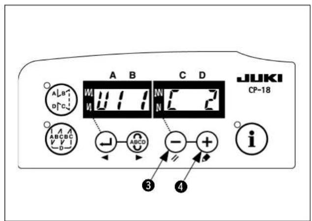
natural_image
Technical line drawing of a mechanical assembly with multiple cylindrical components and mounting brackets (no text or symbols)natural_image
Mechanical assembly diagram showing a valve mechanism with directional arrows (no text or symbols)natural_image
Technical diagram of an engine cylinder assembly with multiple crankshaft heads and mounting brackets (no text or labels)natural_image
Technical line drawing of a mechanical component with an inset close-up showing internal structure (no text or symbols)natural_image
Technical line drawing of a mechanical assembly with no visible text or symbolsnatural_image
Technical line drawing of a mechanical component with crosshair indicators (no text or symbols)natural_image
Diagram showing four sequential steps of a mechanical or robotic arm motion, with no visible text or symbols.natural_image
Technical line drawing of a mechanical component with multiple circular ports and mounting brackets (no text or symbols)5. Adjusting the chain-off thread rolling-in device
natural_image
Technical line drawing of a sewing machine with mechanical components and a numbered label (1), no readable text or symbols present.natural_image
Diagram of a mechanical component with a curved base and internal grooves, labeled with number ① (no text or symbols on the diagram itself)natural_image
Diagram of a mechanical or structural component with no visible text or symbolsnatural_image
Diagram of a mechanical component with threaded end and triangular base, labeled with number ③ (no text or symbols on the diagram itself)1)开始缝的松线针数
开始缝的松线针数可以变更。
2)结束缝松线针数
1)关闭(OFF)电源。
2)一边按开关③一边接通(ON)电源。
1)开始缝的松线针数
开始缝的松线针数可以变更。
2)结束缝松线针数
(1) 压脚提升电磁阀
natural_image
Technical line drawing of a mechanical assembly with multiple cylindrical components and mounting brackets (no text or symbols)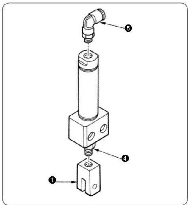
(1) 压脚提升缸筒的组装
(3) 安装地线 ②。
1)缝纫机侧
natural_image
Technical line drawing of a mechanical component with multiple circular components and adjustment knobs (no text or symbols)3)空气配管的确认
natural_image
Technical line drawing of a mechanical component with an inset close-up showing internal structure (no text or symbols)③ 请确认中爪是否被压进针板内。


① CN30 连接马达信号连接器
natural_image
Technical line drawing of a mechanical component with multiple circular components and mounting holes (no text or symbols)(1) 缝迹
natural_image
Technical line drawing of a sewing machine with a numbered component (no text or symbols)natural_image
Diagram of a mechanical component with threaded end and curved top surface, labeled with number ① (no text or symbols on the diagram itself)natural_image
Diagram of a mechanical or electrical component with coiled spring and connecting rod (no text or symbols)natural_image
Diagram of a mechanical component with springs and a triangular load, labeled with number ③ (no text or symbols on the diagram itself)1) Şalteri KAPATIN.

1) Şalteri AÇIN.
natural_image
Technical line drawing of a mechanical assembly with multiple cylindrical components and mounting brackets (no text or symbols)natural_image
Technical diagram of a mechanical component with multiple circular components and adjustment knobs (no text or labels)natural_image
Technical line drawing of a mechanical component with an inset close-up showing internal structure (no text or symbols)
natural_image
Diagram showing four different mechanical or robotic arm configurations with arrows indicating motion direction (no text or symbols present)natural_image
Technical line drawing of a mechanical component with multiple cylindrical ports and mounting holes (no text or symbols)(1) Dikişler
natural_image
Technical line drawing of a sewing machine with mechanical components and a numbered label (1), no readable text or symbols present.natural_image
Diagram of a mechanical component with a curved edge and internal grooves, labeled with number ① (no text or symbols on the diagram itself)natural_image
Diagram of a mechanical or electrical component with coiled spring and connecting rod (no text or symbols)natural_image
Diagram of a mechanical component with a spring-like structure and a triangular load, labeled with number ③ (no text or symbols on the diagram itself)SEWING MACHINERY BUSINESS UNIT
2-11-1, TSURUMAKI, TAMA-SHI,
Copyright © 2005-2011 JUKI CORPORATION
• All rights reserved throughout the world.
Please do not hesitate to contact our distributors or agents in your area for further information when necessary. * The description covered in this instruction manual is subject to change for improvement of the commodity without notice.