
MO6700DA - Sewing machine JUKI - Free user manual and instructions
Find the device manual for free MO6700DA JUKI in PDF.
| Product type | Overlock machine (sewing and overlocking machine) |
| Brand | JUKI |
| Model | MO6700DA (series MO-6704DA, MO-6714DA, MO-6716DA) |
| Maximum sewing speed | 7,000 stitches/min (except certain sub-class models) |
| Stitch length | 0.8 to 4 mm (MO-6704DA); 1.5 to 4 mm (MO-6714DA and MO-6716DA) |
| Needle spacing | 2.0; 2.4; 3.2 mm (MO-6704DA); 2.0; 3.2; 4.0; 4.8 mm (MO-6714DA); 2.0; 3.2; 4.0; 4.8 mm (MO-6716DA) |
| Overlock width | 1.6; 3.2; 4.0; 4.8 mm (MO-6704DA); 3.2; 4.0; 4.8 mm (MO-6714DA); 3.2; 4.0; 4.8; 6.4 mm (MO-6716DA) |
| Differential feed ratio | Gathering 1:2 (max 1:4), Stretching 1:0.7 (max 1:0.6) |
| Standard needle | DC × 27 No. 11 (DC × 1 also usable) |
| Presser foot lift height | 7.0 mm (MO-6704DA); 6.5 mm (MO-6714DA); 7.0 mm (MO-6716DA) |
| Lubrication | JUKI Machine Oil 18; JUKI grease A for compartments |
| Sound level (at workplace) | L_pA = 82.5 dB (K_pA = 2.5 dB) at 6,500 stitches/min (per ISO 10821) |
| Sound power level | L_WA = 90.0 dB (K_WA = 2.5 dB) at 6,500 stitches/min (per ISO 10821) |
| Power supply | Single phase, rated voltage ±10% (grounded power outlet) |
| Operating ambient temperature | 5 to 35 °C |
| Operating relative humidity | 35 to 85% |
| Approximate weight | Approximately 45 kg (head only, without table) |
| Dimensions (head only) | Approximately 600 × 300 × 400 mm (estimate) |
| Routine maintenance | Daily cleaning of lint, regular oiling, oil change every 6 months, grease addition annually or every 2 years |
| Safety | Safety devices (belt cover, eye guard); emergency stop; mandatory grounding; do not open electrical box when powered |
| Spare parts and repairability | Use only JUKI parts; repairs by authorized technician; standard fuse (replace with new one after turning off power) |
Frequently Asked Questions - MO6700DA JUKI
User questions about MO6700DA JUKI
0 question about this device. Answer the ones you know or ask your own.
Ask a new question about this device
Download the instructions for your Sewing machine in PDF format for free! Find your manual MO6700DA - JUKI and take your electronic device back in hand. On this page are published all the documents necessary for the use of your device. MO6700DA by JUKI.
USER MANUAL MO6700DA JUKI
TO ENSURE SAFE USE OF YOUR SEWING MACHINE
For the sewing machine, automatic machine and ancillary devices (hereinafter collectively referred to as "machine"), it is inevitable to conduct sewing work near moving parts of the machine. This means that there is always a possibility of unintentionally coming in contact with the moving parts. Operators who actually operate the machine and maintenance personnel who are involved in maintenance and repair of the machine are strongly recommended to carefully read to fully understand the following Safety precautions before using/maintaining the machine. The content of the Safety precautions includes items which are not contained in the specifications of your product.
The risk indications are classified into the following three different categories to help understand the meaning of the labels. Be sure to fully understand the following description and strictly observe the instructions.
(I) Explanation of risk levels

DANGER :
This indication is given where there is an immediate danger of death or serous injury if the person in charge or any third party mishandles the machine or does not avoid the dangerous situation when operating or maintaining the machine.

WARNING :
This indication is given where there is a potentiality for death or serious injury if the person in charge or any third party mishandles the machine or does not avoid the dangerous situation when operating or maintaining the machine.

CAUTION :
This indication is given where there is a danger of medium to minor injury if the person in charge or any third party mishandles the machine or does not avoid the dangerous situation when operating or maintaining the machine.

Items requiring special attention
(Ⅱ) Explanation of pictorial warning indications and warning labels
| Pictorial warning indication |  | There is a risk of injury if contacting a moving section. | Pictorial warning indication | Be aware that holding the sewing machine during operation can hurt your hands. | |
 | There is a risk of electrical shock if contacting a high-voltage section. | There is a risk of entanglement in the belt resulting in injury. | |||
 | There is a risk of a burn if contacting a high-temperature section. | There is a risk of injury if you touch the button carrier. | |||
 | Be aware that eye deficiency can be caused by looking directly at the laser beam. | Indication label | The correct direction is indicated. | ||
 | There is a risk of contact between your head and the sewing machine. | Connection of a earth cable is indicated. |


- There is the possibility that slight to serious injury or death may be caused.
- There is the possibility that injury may be caused by touching moving part.
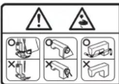
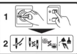
② · To perform sewing work with safety guard.
• To perform sewing work with safety cover.
• To perform sewing work with safety protection device.
③ Be sure to turn the power OFF before carrying out "machine-head threading," "needle changing," "bobbin changing" or "oiling and cleaning.

△危険
Hazardous voltage will cause injury.
Turn off main switch and unplug power cord and wait at least 5 minutes before opening this cover.

DANGER
- When it is necessary to open the control box containing electrical parts, be sure to turn the power off and wait for five minutes or more before opening the cover in order to prevent accident leading to electrical shock.

CAUTION
Basic precaution
- Be sure to read the instruction manual and other explanatory documents supplied with accessories of the machine before using the machine. Carefully keep the instruction manual and the explanatory documents at hand for quick reference.
- The content of this section includes items which are not contained in the specifications of your product.
- Be sure to wear safety goggles to protect against accident caused by needle breakage.
- Those who use a heart pacer have to use the machine after consultation with a medical specialist.
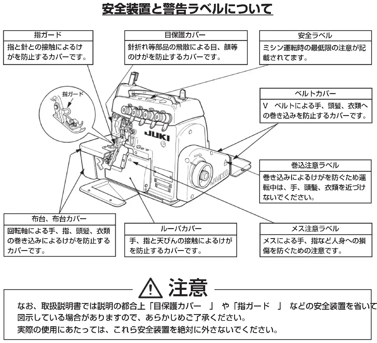
Safety devices and warning labels
- Be sure to operate the machine after verifying that safety device(s) is correctly installed in place and works normally in order to prevent accident caused by lack of the device(s).
- If any of the safety devices is removed, be sure to replace it and verify that it works normally in order to prevent accident that can result in personal injury or death.
- Be sure to keep the warning labels adhered on the machine clearly visible in order to prevent accident that can result in personal injury or death. If any of the labels has stained or come unstuck, be sure to change it with a new one.
Application and modification
- Never use the machine for any application other than its intended one and in any manner other than that prescribed in the instruction manual in order to prevent accident that can result in personal injury or death. JUKI assumes no responsibility for damages or personal injury or death resulting from the use of the machine for any application other than the intended one.
- Never modify and alter the machine in order to prevent accident that can result in personal injury or death. JUKI assumes no responsibility for damages or personal injury or death resulting from the machine which has been modified or altered.
Education and training
- In order to prevent accident resulting from unfamiliarity with the machine, the machine has to be used only by the operator who has been trained/educated by the employer with respect to the machine operation and how to operate the machine with safety to acquire adequate knowledge and operation skill. To ensure the above, the employer has to establish an education/training plan for the operators and educate/train them beforehand.
Items for which the power to the machine has to be turned off
Turning the power off: Turning the power switch off, then removing the power plug from the outlet. This applies to the following.
- Be sure to immediately turn the power off if any abnormality or failure is found or in the case of power failure in order to protect against accident that can result in personal injury or death.
- To protect against accident resulting from abrupt start of the machine, be sure to carry out the following operations after turning the power off. For the machine incorporating a clutch motor, in particular, be sure to carry out the following operations after turning the power off and verifying that the machine stops completely.
2-1. For example, threading the parts such as the needle, looper, spreader etc. which have to be threaded, or changing the bobbin.
2-2. For example, changing or adjusting all component parts of the machine.
2-3. For example, when inspecting, repairing or cleaning the machine or leaving the machine. - Be sure to remove the power plug by holding the plug section instead of the cord section in order to prevent electrical-shock, earth-leakage or fire accident.
- Be sure to turn the power off whenever the machine is left unattended between works.
- Be sure to turn the power off in the case of power failure in order to prevent accident resulting of breakage of electrical components.
PRECAUTIONS TO BE TAKEN IN VARIOUS OPERATION STAGES
Transportation
-
Be sure to lift and move the machine in a safe manner taking the machine weight in consideration. Refer to the text of the instruction manual for the mass of the machine.
-
Be sure to take sufficient safety measures to prevent falling or dropping before lifting or moving the machine in order to protect against accident that can result in personal injury or death.
- Once the machine has been unpacked, never re-pack it for transportation to protect the machine against breakage resulting from unexpected accident or dropping.
Unpacking
- Be sure to unpack the machine in the prescribed order in order to prevent accident that can result in personal injury or death. In the case the machine is crated, in particular, be sure to carefully check nails. The nails have to be removed.
- Be sure to check the machine for the position of its center of gravity and take it out from the package carefully in order to prevent accident that can result in personal injury or death.
Installation
(I) Table and table stand
- Be sure to use JUKI genuine table and table stand in order to prevent accident that can result in personal injury or death. If it is inevitable to use a table and table stand which are not JUKI genuine ones, select the table and table stand which are able to support the machine weight and reaction force during operation.
- If casters are fitted to the table stand, be sure to use the casters with a locking mechanism and lock them to secure the machine during the operation, maintenance, inspection and repair in order to prevent accident that can result in personal injury or death.
(Ⅱ) Cable and wiring
- Be sure to prevent an extra force from being applied to the cable during the use in order to prevent electrical-shock, earth-leakage or fire accident. In addition, if it is necessary to cable near the operating section such as the V-belt, be sure to provide a space of 30 mm or more between the operating section and the cable.
- Be sure to avoid starburst connection in order to prevent electrical-shock, earth-leakage or fire accident.
- Be sure to securely connect the connectors in order to prevent electrical-shock, earth-leakage or fire accident. In addition, be sure to remove the connector while holding its connector section.
(Ⅲ) Grounding
- Be sure to have an electrical expert install an appropriate power plug in order to prevent accident caused by earth-leakage or dielectric strength voltage fault. In addition, be sure to connect the power plug to the grounded outlet without exceptions.
- Be sure to ground the earth cable in order to prevent accident caused by earth leakage.
(IV) Motor
- Be sure to use the specified rated motor (JUKI genuine product) in order to prevent accident caused by burnout.
- If a commercially available clutch motor is used with the machine, be sure to select one with an entanglement preventive pulley cover in order to protect against being entangled by the V-belt.
Before operation
- Be sure to make sure that the connectors and cables are free from damage, dropout and looseness before turning the power on in order to prevent accident resulting in personal injury or death.
- Never put your hand into the moving sections of the machine in order to prevent accident that can result in personal injury or death. In addition, check to be sure that the direction of rotation of the pulley agrees with the arrow shown on pulley.
- If the table stand with casters is used, be sure to secure the table stand by locking the casters or with adjusters, if provided, in order to protect against accident caused by abrupt start of the machine.
During operation
- Be sure not to put your fingers, hair or clothing close to the moving sections such as the handwheel, hand pulley and motor or place something near those sections while the machine is in operation in order to prevent accident caused by entanglement that can result in personal injury or death.
- Be sure not to place your fingers near the surround area of the needle or inside the thread take-up lever cover when turning the power on or while the machine is in operation in order to prevent accident that can result in personal injury or death.
- The machine runs at a high speed. Never bring your hands near the moving sections such as looper, spreader, needle bar, hook and cloth trimming knife during operation in order to protect your hands against injury. In addition, be sure to turn the power off and check to be sure that the machine completely stops before changing the thread.
- Be careful not to allow your fingers or any other parts of your body to be caught between the machine and table when removing the machine from or replacing it on the table in order to prevent accident that can result in personal injury or death.
- Be sure to turn the power off and check to be sure that the machine and motor completely stop before removing the belt cover and V-belt in order to prevent accident caused by abrupt start of the machine or motor.
- If a servomotor is used with the machine, the motor does not produce noise while the machine is at rest. Be sure not to forget to turn the power off in order to prevent accident caused by abrupt start of the motor.
- Never use the machine with the cooling opening of the motor power box shielded in order to prevent fire accident by overheat.
Lubrication
- Be sure to use JUKI genuine oil and JUKI genuine grease to the parts to be lubricated.
- If the oil adheres on your eye or body, be sure to immediately wash it off in order to prevent inflammation or irritation.
- If the oil is swallowed unintentionally, be sure to immediately consult a medical doctor in order to prevent diarrhea or vomiting.
Maintenance
-
In prevention of accident caused by unfamiliarity with the machine, repair and adjustment has to be carried out by a service technician who is thoroughly familiar with the machine within the scope defined in the instruction manual. Be sure to use JUKI genuine parts when replacing any of the machine parts. JUKI assumes no responsibility for any accident caused by improper repair or adjustment or the use of any part other than JUKI genuine one.
-
In prevention of accident caused by unfamiliarity with the machine or electrical-shock accident, be sure to ask an electrical technician of your company or JUKI or distributor in your area for repair and maintenance (including wiring) of electrical components.
-
When carrying out repair or maintenance of the machine which uses air-driven parts such as an air cylinder, be sure to remove the air supply pipe to expel air remaining in the machine beforehand, in order to prevent accident caused by abrupt start of the air-driven parts.
-
Be sure to check that screws and nuts are free from looseness after completion of repair, adjustment and part replacement.
-
Be sure to periodically clean up the machine during its duration of use. Be sure to turn the power off and verify that the machine and motor stop completely before cleaning the machine in order to prevent accident caused by abrupt start of the machine or motor.
-
Be sure to turn the power off and verify that the machine and motor stop completely before carrying out maintenance, inspection or repair of the machine. (For the machine with a clutch motor, the motor will keep running for a while by inertia even after turning the power off. So, be careful.)
-
If the machine cannot be normally operated after repair or adjustment, immediately stop operation and contact JUKI or the distributor in your area for repair in order to prevent accident that can result in personal injury or death.
-
If the fuse has blown, be sure to turn the power off and eliminate the cause of blowing of the fuse and replace the blown fuse with a new one in order to prevent accident that can result in personal injury or death.
-
Be sure to periodically clean up the air vent of the fan and inspect the area around the wiring in order to prevent fire accident of the motor.
Operating environment
-
Be sure to use the machine under the environment which is not affected by strong noise source (electromagnetic waves) such as a high-frequency welder in order to prevent accident caused by malfunction of the machine.
-
Never operate the machine in any place where the voltage fluctuates by more than "rated voltage ± 10% in order to prevent accident caused by malfunction of the machine.
-
Be sure to verify that the air-driven device such as an air cylinder operates at the specified air pressure before using it in order to prevent accident caused by malfunction of the machine.
-
To use the machine with safety, be sure to use it under the environment which satisfies the following conditions: Ambient temperature during operation 5°C to 35°C
Relative humidity during operation 35 % to 85 %
-
Dew condensation can occur if bringing the machine suddenly from a cold environment to a warm one. So, be sure to turn the power on after having waited for a sufficient period of time until there is no sign of water droplet in order to prevent accident caused by breakage or malfunction of the electrical components.
-
Be sure to stop operation when lightning flashes for the sake of safety and remove the power plug in order to prevent accident caused by breakage or malfunction of the electrical components.
-
Depending on the radio wave signal condition, the machine may generate noise in the TV or radio. If this occurs, use the TV or radio with kept well away from the machine.
-
In order to ensure the work environment, local laws and regulations in the country where the sewing machine is installed shall be followed. In the case the noise control is necessary, an ear protector or other protective gear should be worn according to the applicable laws and regulations.
-
Disposal of products and packages and treatment of used lubricating oil should be carried out properly according to the relevant laws of the country in which the sewing machine is used.
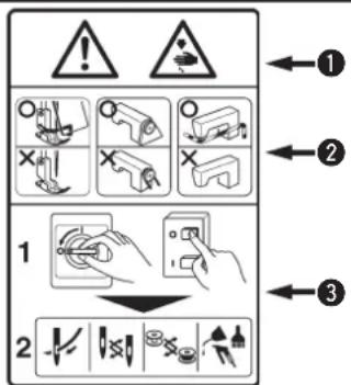
| 1. So as to avoid electric shock hazards, do not open the cover of the electrical box of the motor or touch any part inside the electrical box with the power to the machine turned ON. | |
1. To prevent possible personal injury, never operate the machine with the belt cover and the eye guard removed.2. To protect against possible personal injury resulting from being caught in the motor, use a motor that is provided with a motor pulley cover.3. To avoid electric shock hazards, never operate the machine with the ground wire for the power supply removed.4. During operation, be careful not to allow your or any other person's head, hands or fingers to come close to the handwheel, V belt and motor so as to prevent possible personal injury that may occur when your hands/fingers are caught in the machine. Also, do not place anything close to them.5. So as to avoid possible injury to your hands and fingers, do not put any of them near the cloth cutting knife and the needle when turning the power to the machine or while the machine is in operation.6. To prevent possible injury to your hands and fingers, do not put any of them inside the eye guard while the machine is in operation.7. To avoid electric shock hazards and accidents arising from damaged electrical components, be sure to turn OFF the power switch before inserting/detaching the power plug.8. So as to protect against possible personal injury resulting from abrupt start of the machine, make sure to turn OFF the power to the machine when you leave your machine.9. In the event of a power failure, be sure to turn OFF the power to the machine to protect against possible personal injury resulting from abrupt start of the machine.10. So as to protect against possible personal injury resulting from abrupt start of the machine, remove the belt cover, motor pulley cover and the V belt after turning OFF the power to the machine and confirming that the sewing machine will not run even by depressing the start pedal.11. Before inspecting, adjusting or cleaning the machine, threading the machine head or replacing the needle, so as to protect against possible personal injury resulting from abrupt start of the machine, be sure to turn OFF the power to the machine so as to prevent an accident and confirm that the sewing machine will not operate even when depressing the foot pedal of the sewing machine.12. To protect against personal injury resitting from possible drop of the machine, do not carry your machine by holding the cloth plate cover by hand. Doing so may cause the cover to open or break resulting in drop hazards.13. Be careful of handling this product so as not to pour water or oil, shock by dropping, and the like since this product is a precision instrument.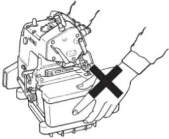 |
DECLARATION OF INCORPORATION OF PARTLY COMPLETED MACHINERY
We hereby declare that the sewing machine (sewing head) described below ;
- Must not be put into service until the machinery to which it is incorporated has been declared in conformity with the provisions of the Directive 2006/42/EC, and
- Conforms to the essential requirements of the Directive 2006/42/EC, described in the technical documentation, and
- To be prepared with the above technical documentation compiled in accordance with part B of Annex VII, and
- Also to conform to the RoHS Directive 2011/65/EU
- Relevant information on which should be transmitted in response to a reasoned request by the national authorities, by the electronic method or other according to the request.
MO-6700S Series, MO-6900S Series
Model MO-6900G Series,MO-6700DA Series
Description Industrial Sewing Machine
Function make stitches and sew
Applied harmonized standards, in particular :
EN ISO12100, EN ISO10821, EN 50581
Manufacturer :
JUKI CORPORATION
2-11-1, Tsurumaki, Tama-shi, Tokyo, Japan
natural_image
Line drawing of a hand holding a mechanical device with a black X mark (no text or symbols)POUR ASSURER L'UTILISATION EN TOUTE SÉCURITÉ DE VOTRE MACHINE À COUDRE

natural_image
Line drawing of a hand holding a mechanical device with a black X mark (no text or symbols)PER GARANTIRE L'USO SICURO DELLA MACCHINA PER CUCIRE
natural_image
Line drawing of a hand holding an engine component with a black X mark (no text or symbols)为了安全地使用缝纫机
( I ) Masa ve tezgah
- Installing the frame support plate....4
- Attaching the belt cover....7
- Installing the pedals....8
- Installing the thread stand....9
- Lubrication....11
- Checking the direction of rotation....13
- Attaching needles....14
- Threading the machine....16
- Adjusting the pressure of the presser foot and removing the presser foot....19
-
Adjusting the stitch length 20
-
Differential feed mechanism 21
IV. MAINTENANCE....23
- Knives and overedge withh....23
- Cleaning the machine head 26
- Dimensions used to adjust the looper and the needle guard 27
4. Dimensions relatrd to the position of the thread take-up and the looper thread cam (standard adjustment)....30
- Motor pulleys and belts 34
V. GREASE REPLENISHMENT....35
- How to replenish the needle bar compartment with grease....35
- How to replenish the looper compartment with grease.... 36
INALT
| MO-6704DA | MO-6714DA | MO-6716DA | |
| Sewing speed | 7,000 sti/min | ||
| (Excluding some subclass models) | |||
| Stitch length | 0.8 to 4 mm | 1.5 to 4 mm | |
| Needle gauge | — | 2.0, 2.4, 3.2 mm | 2.0, 3.2, 4.0, 4.8 mm |
| Overedge width | 1.6, 3.2, 4.0, 4.8 mm | 3.2, 4.0, 4.8 mm | 3.2, 4.0, 4.8, 6.4 mm |
| Differential feed ratio | Gathering stitch 1:2 (Max. 1:4), Stretching stitch 1:0.7 (Max. 1:0.6) | ||
| Needle | DC × 27 (Standard) DC × 1 may be used | ||
| Presser foot lift | 7.0 mm | 6.5 mm | 7.0 mm |
| (Excluding some subclass models) | |||
| Lubricating oil | JUKI Machine Oil 18 | ||
| Noise | - Equivalent continuous emission sound pressure level (LpA) at the workstation:A-weighted value of 82.5 dB; (Includes KpA=2.5 dB); according to ISO 10821-C.6.2-ISO 3744 GR2 at 6,500 sti/min.- Sound power level (LwA);A-weighted value of 90.0 dB; (Includes KwA=2.5 dB); according to ISO 10821-C.6.2-ISO 3744 GR2 at 6,500 sti/min. | ||
I. TECHNISCHE DATEN
1) Poser la bande en mousse de carter de soufflante ② sur le carter de soufflante ①.
2) Poser la carter de soufflante ①, le tampon en caoutchouc ④ et la rondelle-entretoise ⑤ sur la plaque-support du bâti ③.
1) Fissare la spugnetta del contenitore ② al contenitore ①.
2) Fissare il contenitore ①, il tampone di gomma ④ ed il distanziale ⑤ alla piastra ③ di supporto della macchina.
1) Kasa süngerini ② fan muhafazasına ① takın.
2) Muhafazayı ①, lastik takozu ④ ve mesafe elemanını ⑤ kasa destek tablasına ③ takın.
natural_image
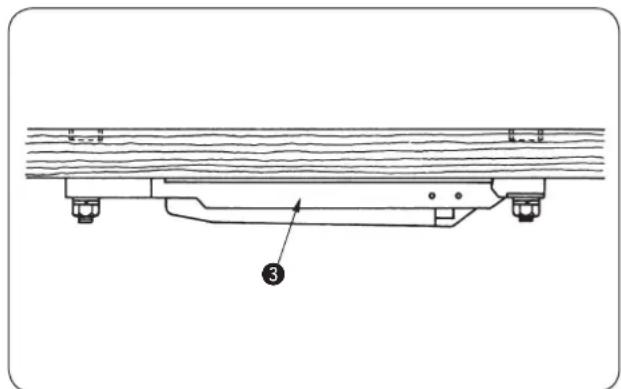
Technical line drawing of a structural support frame with no visible text or symbols1) Attatch case sponge ② to blower case ①.
2) Attach blower case ①, rubber cushion ④ and spacer ⑤ to frame support plate ③.
1) Poser la bande en mousse de carter de soufflante ② sur le carter de soufflante ①.
2) Poser la pièce de jonction de plaque-support du bâti ④, le carter de soufflante ① et le tampon en caoutchouc ⑤ sur la plaque-support du bâti ③.
1) Fissare la spugnetta del contenitore ② al contenitore ①.
2) Fissare il giunto ④ della piastra di supporto della fusione, il contenitore ① e il tampone di gomma ⑤ alla piastra ③ di supporto della macchina.
1) Kasa süngerini ② muhafazaya ① takın.
2) Kasa desteği plaka bağlantısını ④ muhafazaya ① ve lastik takozu ⑤, kasa destek plakasına ③ takın.
2) Attach frame support plate joint ④, blower case ① and rubber cushion ⑤ to frame support plate ③.
3) Install frame support plate ③ so that the cloth plate is 5 mm higher than the surface of the machine table.
4) Attach waste chute ⑥ to frame support plate ①.
To protect against possible personal injury due to abrupt start of the machine, be sure to start the following work after turning the power off and ascertaining that the motor is at rest.
WARNUNG :
1) Install belt cover ① to the machine head.
2) Install belt cover B ② to the table.
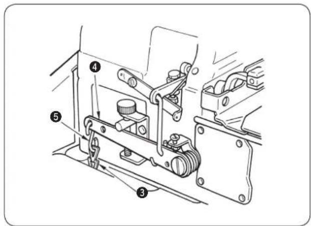
1) Install starting pedal ① on the left and presser lifter pedal ② on the right as seen from the operator.
2) Use an S-shaped hook ⑤ to connect the chain ③ of the presser lifter pedal to presser lifting lever ④.
1) Assemble the thread stand unit, and insert it in the hole in the machine table.
2) Tighten locknut ① to fix the thread stand.
3) For ceiling wiring, pass the power cord through spool rest rod ②.
To avoid malfunction and damage of the machine, confirm the following:
- Before you put the machine into operation for the first time after set-up, clean it thoroughly.
- Remove all dust gathering during transportation and oil it well.
- Confirm that the voltage has been correctly set.
- Confirm that the power plug has been properly connected to the power supply.
- Never use the machine in the state where the voltage type is different from the designated one.
To protect against possible personal injury due to abrupt start of the machine, be sure to start the following work after turning the power off and ascertaining that the motor is at rest.
WARNUNG :
1) Remove oil cap ①.
2) Pour JUKI Machine Oil 18 into the oil reservoir.
3) Supply oil until the pointer bar almost reaches the upper red marker line when oil gauge ② is observed from the side.

Be careful not to exceed the upper red marker line, or else troubles due to excessive lubrication may result.
4) Remove oil drain cap reservoir.
③ when draining the oil
natural_image
Technical line drawing of a mechanical component with a cat-shaped opening and a close-up inset showing a cylindrical feature (no text or symbols)
Change oil when one month has passed after the first set-up of the sewing machine. Then, change oil every six months.
- If the pointer bar of the oil gauge comes down under the lower marker line when observing the oil gauge from sideward, supply oil.

natural_image
Line drawing of a JUKI sewing machine (no text or symbols visible)1) The correct direction of rotation of the sewing machine is clockwise. Never allow the machine to rotate in the reverse direction. If the machine rotates counterclockwise, the oil pump will fail to function resulting in seizure.
To protect against possible personal injury due to abrupt start of the machine, be sure to start the following work after turning the power off and ascertaining that the motor is at rest.
WARNUNG :
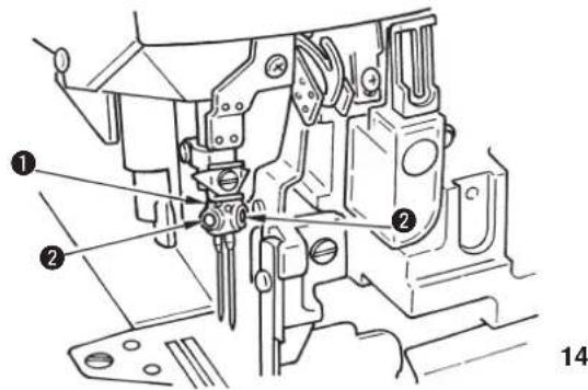
The standard needle is DC × 27 #11. You can also use the DC × 1 needle. In this case, however, the clearance provided between the needle and the looper may be required to be adjusted. If sewing need to be carried out with a finely adjusted thread tension, use the DC × 27 needle.
1) Bring needle clamp ① to the highest position.
2) Loosen needle clamp screw ②, and fully insert the needle into the needle clamp hole with the needle recess facing backwards as viewed from the operator's side.
3) Tighten the needle clamp screw ②.
* 一部サブクラスを除きます。 / Excluding some subclass models /
Ausschließlich gewisser Subklassen-Modelle / Sauf certains modèles de sous-classe /
Excluyendo algunos modelos subclase / Escluse alcune sottoclassi di modello /
派生机种除外 / Bazı alt sınıf modeller hariç

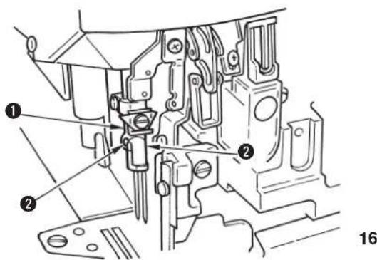
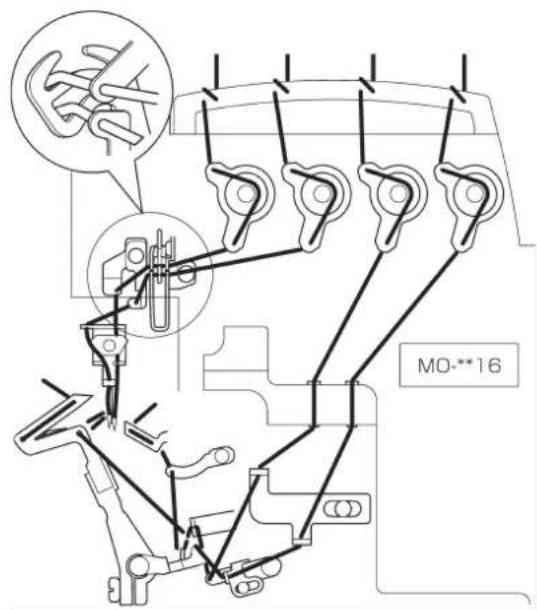
Raise looper thread cam thread guide ① and perform threading. Return looper thread cam thread guide ① to its home position and securely fix it to retsining spring ②.

Be sure to pass the needle thread for double chainstitch through the needle thread take-up lever.
(Pass the needle thread for overlocking through the thread take-up lever located outside.)

natural_image
Technical line drawing of an engine cylinder head with mounting holes and internal components (no text or symbols)
When using an untwisted thread such as wooly nylon thread or weak thread, do not wind it round the intermediate thread guide.

★ Lubrication the needle cooler (Optional installation)
1) Open cloth plate cover and supply silicon oil from section A.
2) Remove plug Ⓑ, and supply silicon oil.
3) Infiltrate silicon oil also into the oil felt if the machine is started immediately after lubricating the needle cooler.
natural_image
Pure mechanical diagram showing a U-shaped component with a handle and circular base, no text or symbols present.When the needle cooler is used. Pass the thread under the center pawl.
natural_image
Pure mechanical diagram showing a lever and handle without any text, numbers, or symbolsWhen the needle cooler is not used. Pass the thread above the center pawl.
1) Adjust the pressure of the presser foot by loosening first nut ④ and turning presser foot adjust screw ①.
When the adjust s crew is turned clockwise, the pressure will increase. When it is turned counterclockwise, the pressure will decrease.
After the adjustment, be sure to turn nut ④ without fail.
2) To open presser foot ② sidewayd, raise the needle to the highest position of its stroke and lower presser bar lifting lever ③.
To protect against possible personal injury due to abrupt start of the machine, be sure to start the following work after turning the power off and ascertaining that the motor is at rest.
WARNUNG :
1) Slowly turn the handwheel as you keep depressing pushbutton ①, and you will find a point at which the pushbutton goes in farther.
2) With the above condition maintained, align the desired scale mark on the handwheel with mark ② on the belt cover.
3) Reset the pushbutton ① after setting the dial.
7. 差動送りの調節 Differential feed mechanism /
Differentialtransportmechanismus / Mecanisme d'entrainment differentiel / Mecanismo de transporte diferencial / Meccanismo di trasporto differenziale / 差动送布的调节 / Diferansiyel besleme mekanizmasi
注意:
To protect against possible personal injury due to abrupt start of the machine, be sure to start the following work after turning the power off and ascertaining that the motor is at rest.
WARNUNG :
1) Loosen differential feed lock nut ②. Move lever ① up for stretching stitch or down for gathering stitch.
2) When you want to move the lever ① only slightly, use differential feed minute-adjust screw ③.
3) When the differential feed adjusting lever is set to graduation S, the machine will perform stretching with a differential feed ratio of 1:0.8 (some of subclass models: 1:0.6).
When the lever is set to graduation 0, the differential feed ratio between the main feed dog and the differential feed dog will be 1:1.
4) The maximum differential feed ratio for gathering is 1:2 (some of subclass models: 1:1.75). The graduations beyond 0 are used as standard.
(It can be set to 1:4 (some of subclass models: 1:3.8) depending on the adjustment of the internal mechanism of the sewing machine.)
5) After the adjustment, securely tighten locknut ②.
To protect against possible personal injury due to abrupt start of the machine, be sure to start the following work after turning the power off and ascertaining that the motor is at rest.
WARNUNG :
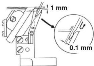
★ Height of the lower knife
Loosen setscrew ② and adjust the height of lower knife ① so that its edge is flush with the throat plate surface.
★ Height of the upper knife
Loosen setscrews ④, and perform adjustment so that upper knife ③ overlaps lower knife ① 0.5 to 1 mm when the upper knife is at its lower point.
★ Overedge width
Overedge widths of 1.6 through 6.4 mm (some of subclass models: 4.8 through 10 mm) are provided by changing the parts or by using subclass models. (The overedge width will be slightly larger than the knife cut width.)
To change the overedge width:
1) Loosening setscrew ⑤, push lower knife ① to the left and fix it.
2) Loosen setscrew ⑥ and move upper knife ③ as required, then fix it.
3) Lower the upper knife to its lowest point and loosen setscrew ⑤. Tighten setscrew ⑤ when the lower knife comes in contact with the upper knife.
- Be sure to tighten screw ⑤ before operating machine.
- After the completion of adjustment, make the knives cut a thread to check for sharpness of the knives.

★ Resharpening the lower knife
When the lower knife has become dull, resharpen it as shown in the figure left.
To protect against possible personal injury due to abrupt start of the machine, be sure to start the following work after turning the power off and ascertaining that the motor is at rest.
WARNUNG :
natural_image
Technical line drawing of a mechanical assembly with no visible text or symbols1) Clear lint from inside the looper cover and the needle bar and components about once or twice a day. If not, the sewing material will be soiled.

Do not wipe the coated surface of the machine head with lacquer thinner. Doing so will damage the coated surface.
To protect against possible personal injury due to abrupt start of the machine, be sure to start the following work after turning the power off and ascertaining that the motor is at rest.
WARNUNG :
-
To avoid possible accidents due to unfamiliarity with the machine, get a maintenance man who has a good knowledge of the machine or serviceman of our distributor to adjust the machine or replace any of its parts.
-
To avoid possible personal injury when the machine starts, it has to be ascertained in prior to the actuation of the machine that no screws are loosened and no components come in contact with one another.

The dimensions given in the table are standard ones to be used to adjust the looper. They are intended to be used for reference and should be changed more or less in accordance with the sewing products and thread to be used.

VORSICHT :
natural_image
Diagram of a mechanical tool with a magnified inset showing a hand holding a tool (no text or symbols present)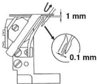
- 天びん、下糸カム位置寸法値(標準合わせ)/ Dimensions related to the position of the thread take-up and the looper thread cam (standard adjustment) / Masse für die position von fadenhebel und greiferfadenhebenocken (standardeinstellung) / Cotes relatives a la position du releveur de fil et de la came de fil de boucleur (reglage standard) / Dimensiones relacionadas con la posicion del tirahilo y de la leva del hilo del enlazador (ajuste estandar) / Misure relative alla posizione del tirafilo e della cam filo del crochet (regolazione standard) / 挑线杆、底线凸轮位置尺寸(标准调整)/ İplik verici ile lüper iplik kamının konum ölçüleri (standart ayar)

注意:
To protect against possible personal injury due to abrupt start of the machine, be sure to start the following work after turning the power off and ascertaining that the motor is at rest.
WARNUNG :
natural_image
Line drawing of a mechanical clamp or clamp mechanism with no text or symbolsThe thread hole in the needle thread eyelet and the hooked portion of the needle thread take-up are in the position where two-thirds of the entire hole in the needle thread eyelet can be observed.
The thread hole in the needle thread eyelet and the hooked portion of the needle thread take-up are in the position where two-thirds of the entire hole in the needle thread eyelet can be observed.
The thread hole in the needle thread eyelet and the hooked portion of the needle thread take-up are in the position where two-thirds of the entire hole in the needle thread eyelet can be observed.
natural_image
Line drawing of a mechanical clamp or clip assembly with no text or symbolsThe thread hole in the double chainstitch needle thread eyelet and the hooked portion of the needle thread take-up are in the position where the entire hole in the double chainstitch needle thread eyelet can be observed.
natural_image
Diagram of a hand holding a tool with a curved handle and directional arrows indicating movement (no text or symbols)(Unit : mm) .(Birim: mm)
| A | B | C | D | E | F | G | H | I | J | ||
| 04 | 65 22 | 43.5 | 17.5 | 38 2 | 6.5 11 | 29 | 27 1 | ||||
| 14 | 65 22 | 43.5 | 17.5 | 38 2 | 6.5 11 | 29 | 22 1 | ||||
| 16 | 65 22 | 43.5 | 17.5 | 34 2 | 6.5 11 | 27.5 | 20 1 | ||||
(3) 下糸力ム調整値 Adjustment value for the looper thread cam /
natural_image
Diagram of a mechanical device with rotating wheel and housing (no text or symbols)Make sure that the looper thread cam releases the looper thread.

For the general use of the sewing machine, it is not necessary to add grease. If you use the sewing machine under particularly severe conditions, periodical replenishment of the exclusive grease (approximately once every one or two years) will be effective to ensure smooth operation of the machine.
1) Remove grease replenishing rubber plug ① from the needle bar compartment.
2) Replenish grease by means of a tip of screwdriver ③, ② or the like. Use JUKI GREASE A for the replenishment of grease
JUKI GREASE A: 40006323 (part number)

natural_image
Technical line drawing of a mechanical assembly with no visible text or symbols

For the general use of the sewing machine, it is not necessary to add grease. If you use the sewing machine under particularly severe conditions, periodical replenishment of the exclusive grease (approximately once every one or two years) will be effective to ensure smooth operation of the machine.
1) Remove grease replenishing rubber plug ① from the looper compartment.
2) Replenish grease by means of a tip of screwdriver ③, ② or the like. Use JUKI GREASE A for the replenishment of grease
JUKI GREASE A: 40006323 (part number)

SEWING MACHINERY BUSINESS UNIT
2-11-1, TSURUMAKI, TAMA-SHI,
Copyright © 2010-2013 JUKI CORPORATION
- All rights reserved throughout the world.
Please do not hesitate to contact our distributors or agents in your area for further information when necessary.
* The description covered in this instruction manual is subject to change for improvement of the commodity without notice.