
DDL9000A - Sewing machine JUKI - Free user manual and instructions
Find the device manual for free DDL9000A JUKI in PDF.
| Product type | Industrial lockstitch sewing machine |
| Brand | Juki |
| Model | DDL-9000A |
| Maximum sewing speed | 5,000 stitches/min (variable by version: 4,000 or 4,500 stitches/min) |
| Maximum stitch length | 5 mm (limited to 4 mm at speed ≥ 4,000 stitches/min) |
| Presser foot lift height | 10 mm (standard), 15 mm (maximum) |
| Compatible needles | DB×1 No. 9 to No. 23, DP×5 No. 65 to No. 160 (depending on version) |
| Lubricating oil | JUKI NEW DEFRIX OIL No. 1 or JUKI MACHINE OIL No. 7 |
| Lubrication system | Hook lubrication by oil splash, with micro-quantity (S), semi-dry (M), or dry (D) depending on version |
| Thread trimmer device | Integrated, controlled by pedal or optional switch |
| Programmable needle up/down stop | Yes, adjustable via electrical parameters |
| Automatic backstitching | Yes, with stitch length regulation (standard 4 mm) |
| Pedal control | Adjustable (stroke, forward/backward resistance) |
| Integrated bobbin winder | Yes, with automatic stop and tension adjustment |
| Thread take-up (option) | Available as option, with deactivation switch |
| Optional switch | Allows stitch compensation, thread trimming, foot lift, etc. |
| Power supply | Single-phase, grounded plug; check voltage and phase |
| Safety devices | Finger guard, grounding, safety switch when tilting the head |
| Daily maintenance | Check oil level (between gauge marks), clean needle, presser foot, feed dog and hook |
| Brochure | 79-page manual downloadable in PDF format |
Frequently Asked Questions - DDL9000A JUKI
User questions about DDL9000A JUKI
0 question about this device. Answer the ones you know or ask your own.
Ask a new question about this device
Download the instructions for your Sewing machine in PDF format for free! Find your manual DDL9000A - JUKI and take your electronic device back in hand. On this page are published all the documents necessary for the use of your device. DDL9000A by JUKI.
USER MANUAL DDL9000A JUKI
Putting sewing systems into operation is prohibited until it has been ascertained that the sewing systems in which these sewing machines will be built into, have conformed with the safety regulations in your country. Technical service for those sewing systems is also prohibited.
- Observe the basic safety measures, including, but not limited to the following ones, whenever you use the machine.
- Read all the instructions, including, but not limited to this Instruction Manual before you use the machine.
In addition, keep this Instruction Manual so that you may read it at anytime when necessary. - Use the machine after it has been ascertained that it conforms with safety rules/standards valid in your country.
- All safety devices must be in position when the machine is ready for work or in operation.
The operation without the specified safety devices is not allowed. - This machine shall be operated by appropriately-trained operators.
- For your personal protection, we recommend that you wear safety glasses.
- For the following, turn off the power switch or disconnect the power plug of the machine from the receptacle.
7-1 For threading needle(s), looper, spreader etc. and replacing bobbin.
7-2 For replacing part(s) of needle, presser foot, throat plate, looper, spreader, feed dog, needle guard, folder, cloth guide etc.
7-3 For repair work.
7-4 When leaving the working place or when the working place is unattended.
7-5 When using clutch motors without applying brake, it has to be waited until the motor stopped totally. -
If you should allow oil, grease, etc. used with the machine and devices to come in contact with your eyes or skin or swallow any of such liquid by mistake, immediately wash the contacted areas and consult a medical doctor.
-
Tampering with the live parts and devices, regardless of whether the machine is powered, is prohibited.
-
Repair, remodeling and adjustment works must only be done by appropriately trained technicians or specially skilled personnel. Only spare parts designated by JUKI can be used for repairs.
-
General maintenance and inspection works have to be done by appropriately trained personnel.
-
Repair and maintenance works of electrical components shall be conducted by qualified electric technicians or under the audit and guidance of specially skilled personnel.
Whenever you find a failure of any of electrical components, immediately stop the machine.
-
Before making repair and maintenance works on the machine equipped with pneumatic parts such as an air cylinder, the air compressor has to be detached from the machine and the compressed air supply has to be cut off. Existing residual air pressure after disconnecting the air compressor from the machine has to be expelled. Exceptions to this are only adjustments and performance checks done by appropriately trained technicians or specially skilled personnel.
-
Periodically clean the machine throughout the period of use.
-
Grounding the machine is always necessary for the normal operation of the machine. The machine has to be operated in an environment that is free from strong noise sources such as high-frequency welder.
-
An appropriate power plug has to be attached to the machine by electric technicians. Power plug has to be connected to a grounded receptacle.
-
The machine is only allowed to be used for the purpose intended. Other used are not allowed.
-
Remodel or modify the machine in accordance with the safety rules/standards while taking all the effective safety measures. JUKI assumes no responsibility for damage caused by remodeling or modification of the machine.
-
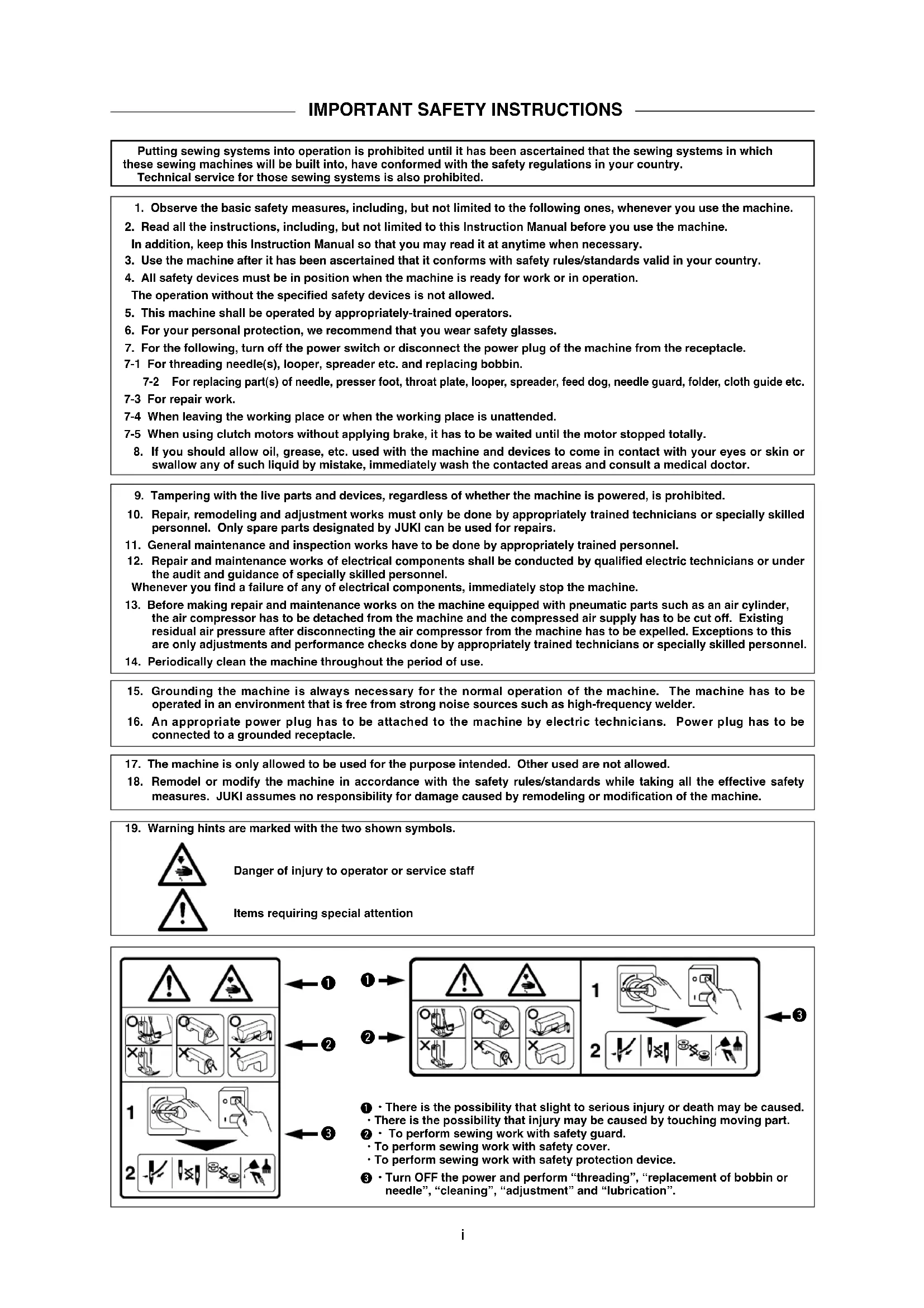
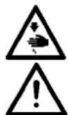
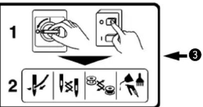
Warning hints are marked with the two shown symbols.
Danger of injury to operator or service staff
Items requiring special attention
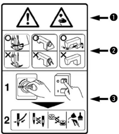
① · There is the possibility that slight to serious injury or death may be caused.
- There is the possibility that injury may be caused by touching moving part.
② · To perform sewing work with safety guard.
• To perform sewing work with safety cover.
• To perform sewing work with safety protection device.
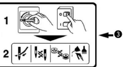
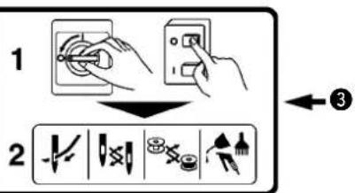
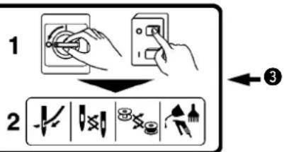
3 · Turn OFF the power and perform “threading”, “replacement of bobbin or needle”, “cleaning”, “adjustment” and “lubrication”.
FOR SAFE OPERATION
| 1. To avoid personal injury, never put your fingers under the needle when you turn ON the power switch or operate the sewing machine.2. To avoid personal injury, never put your fingers into the thread take-up cover while the sewing machine is in operation.3. To avoid personal injury, turn OFF the power switch when you tilt the machine head.4. To prevent possible personal injury caused by being caught in the machine, keep your fingers, head and clothes away from the handwheel and the thread take-up while the sewing machine is in operation. In addition, place nothing around it.5. To avoid personal injury, never operate the sewing machine with the finger guard removed.6. To avoid personal injury, be careful not to allow your fingers in the machine when tilting the machine head. | |
1. For the safety, never operate the sewing machine with the ground wire for the power supply removed.2. Be sure to turn OFF the power switch in prior when connecting/disconnecting the power plug.3. When thunders occurs, stop the work for the safety and disconnect the power plug.4. When the sewing machine is suddenly moved from a cold place to a warm place, there is a case where dew condensation may occur. Turn ON the power after there is no worry of the drop of water.5. To prevent fires, periodically draw out the power plug from the plug socket and clean the root of the pins and the space between pins.6. The hook rotates at a high speed while the machine is in operation.To prevent possible injury to hands, be sure to keep your hands away from the vicinity of the hook during operation. In addition, be sure to turn OFF the power to the machine when replacing the bobbin.7. The motor does not produce noise while the machine is at rest.To avoid possible accidents due to abrupt start of the machine, be sure to turn OFF the power to the machine.8. Be careful of handling this product so as not to pour water or oil, shock by dropping, and the like since this product is a precision instrument.9. When tilting or returning the sewing machine to the home position, hold the upper side of the machine head with both hands and perform the work quietly so that fingers or the like are not caught in the machine.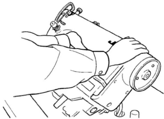 |

WARNING :
To avoid malfunction and damage of the machine, confirm the following.
- Remove the air-vent cap (red color) attached to the sewing machine bed.
- Clean the sewing machine thoroughly before using it for the first time.
- Remove all dust collected on the sewing machine during the transportation.
- Confirm that the voltage and phase are correct.
- Confirm that the power plug is properly connected.
- Never use the sewing machine in the state where the voltage type is different from the designated one.
- The direction of rotation of the sewing machine is counterclockwise as observed from the handwheel side. Be careful not to rotate it in reverse direction.
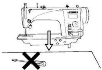
- Do not tilt the machine head toward this side since oil leakage or parts breakage occurs.
- A safety switch is installed so that the sewing machine cannot be operated with the machine head tilted.
- When operating the sewing machine, turn ON the power switch after properly setting the head on the table.
- Before starting a test run, remove the bobbin case and the needle thread from the machine.
- Operate the handwheel after the sewing machine has totally stopped.
重要安全事项
flowchart
graph TD
    A["1: Warning"] --> B["2: Inspection"]
    B --> C["3: Application"]

flowchart
graph TD
    A["1: Warning"] --> B["2: Inspection"]
    B --> C["3: Application"]
| -SS | -SH | -MS | -MA ^3 | -DS | |
| Max. sewing speed | 5,000 rpm | 4,500 rpm | 5,000 rpm | 4,000 rpm | |
| Stitch length | 5mm ^-1 | 4mm 5mm ^-1 | |||
| Presser foot lift(by knee lifter) | 10 mm (standard) 15 mm (max.) | ||||
| Needle ^2 | DB×1#9 to #18DP×5#65 to #110 | DB×1#20 to #23DP×5#125 to #160 | DB×1#9 to #18DP×5#65 to #110 | DB×1SF#8 to #11DP×5#60 to #75 | DB×1#9 to #18DP×5#65 to #110 |
| Lubricating oil | JUKI NEW DEFRIX OIL No. 1 or JUKI MACHINE OIL #7 | - | |||
| Noise | Workplace-related noise at sewing speedn = 5,000 min ^-1 : LpA ≤80.5 dB (A)Noise measurement according to DIN 45635-48-A-1. | ||||
- Sewing speed varies in accordance with the sewing conditions. Sewing speed at the time of delivery is 4,000 rpm.
* 1: When stitch length exceeds 4 mm or more, set the max. sewing speed to 4,000 rpm or less for use. In addition, the amount of reverse feed has been regulated to 4 mm at the time of delivery. Release the regulation when using the machine with the amount more than the regulated one.
* 2 : Needle used depends on the destination.
*3 : MA type is for light-weight materials. When using the machine at a speed of 4,000 rpm or more, replace the presser adjusting spring, the thread tension spring, etc. for S type.
规格
| -SS | -SH | -MS | -MA ^3 | -DS | |
| 最高缝制速度 | 5,000 rpm | 4,500 rpm | 5,000 rpm | 4,000 rpm | |
| 最大针脚长度 | 5mm ^1 | 4mm | 5mm ^1 | ||
| 压脚高度(膝动提升) | 10mm(标准) 15mm(最大) | ||||
| 使用机针 ^2 | DB×1#9~#18DP×5#65~#110 | DB×1#20~#23DP×5#125~#160 | DB×1#9~#18DP×5#65~#110 | DB×1SF#8~#11DP×5#60~#75 | DB×1#9~#18DP×5#65~#110 |
| 使用机油 | JUKI NEW DEFRIX OIL No.1或 JUKI MACHINE Oil #7 | - | |||
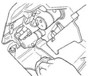
natural_image
Line drawing of hands operating a sewing machine with no visible text or symbols2)
1) Carry the sewing machine with two persons as shown in the figure above.
(Caution) Do not hold the handwheel.
2) Do not place any protruding thing such as screwdriver and the like on the place where the sewing
3) The under cover should rest on the fo corners of the machine table groove.
4) Fix two rubber seats ① on side A (operator's side) using nails ② as illustrated above. Fix two cushion seats ③ on side B (hinged side) using a rubber-based adhesive. Then place under cover ④ on the fixed seats.
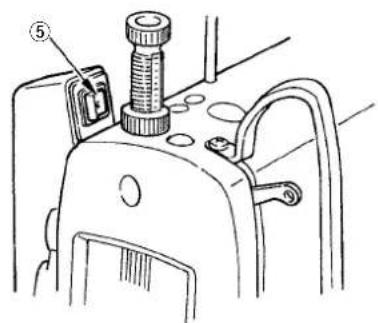
5) Remove air vent cap ⑤ attached to the machine bed.
(Caution)
- If the sewing machine is operated without removing air vent cap ⑤, oil leakage from gear box portion C may occur.
- Be sure to attach cap ⑤ when transporting the machine head in the state that the machine head is removed from the machine table.
6) Fit knee lifter pressing rod ⑥. Fit hinge ⑦ into the opening in the machine bed, and fit the machine head to table rubber hinge ⑧ before placing the machine head on cushions ⑨ on the four corners.
7) Securely attach head support rod 10 to the table until it goes no further. (However, in case of the machine with AK device 11, it is not necessary.) In case of using control panel 12, remove two side plate setscrews 13, insert rubber packing 14 among the accessories of control panel 12 between the machine head and 12, and fix the control panel.
(Caution) Do not use the screws supplied as accessories of control panel ②.
8) Bundle cable clip band 15 supplied as accessories of the machine head at the root of the cable.
Turn OFF the power before starting the work so as to prevent accidents caused by abrupt start of the sewing machine.
The standard height of the presser foot lifted using the knee lifter is 10 mm. You can adjust the presser foot lift up to 15 mm using knee lifter adjust screw ^① . (Caution)
Do not operate the sewing machine in the state that the preser foot ③ is lifted by 10 mm or more since the needle bar ② comes in contact with the presser foot ③.

注意:
1) Assemble the thread stand unit, and insert it in the hole in the machine table.
2) Tighten nut ①.
3) For ceiling wiring, pass the power cord through spool rest rod ②.
natural_image
Mechanical assembly diagram showing a spring-loaded bracket with bolts and nuts (no text or labels)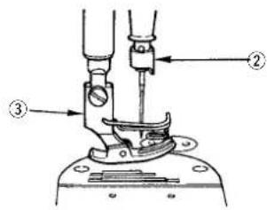
AVISO :
-
Do not connect the power plug until the lubrication has been completed so as to prevent accidents due to abrupt start of the sewing machine,
-
To prevent the occurrence of an inflammation or rash, immediately wash the related portions if oil adheres to your eyes or other parts of your body.
-
If oil is mistakenly swallowed, diarrhea or vomiting may occur. Put oil in a place where children cannot reach.
Fill the oil tank with oil for hook lubrication before operating the sewing machine.
1) Remove oil hole cap ① and fill the oil tank with JUKI NEW DEFRIX OIL No.1 (Part No.: MDFRX1600C0) or JUKI MACHINE OIL #7 (Part No.: MML007600CA) using the oiler supplied with the machine.
2) Fill the oil tank with the oil until the top end of oil amount indicating rod ③ comes between the upper engraved marker line A and the lower engraved marker B line of oil amount indicating window ②.
If the oil is filled excessively, it will leak from the air vent hole in the oil tank or proper lubrication will be not performed. In addition, when the oil is vigorously filled, it may overflow from the oil hole. So, be careful.
3) When you operate the sewing machine, refill oil if the top end of oil amount indicating rod ③ comes down to the lower engraved marker line of oil amount indicating window ②.
(Caution)
-
When you use a new sewing machine or a sewing machine after an extended period of disuse, use the sewing machine after performing break-in at 2,000 rpm or less.
-
For the oil for hook lubrication, purchase JUKI NEW DEFRIX OIL No. 1 (Part No.: MDFRX1600C0) or JUKI MACHINE OIL #7 (Part No.: MML007600CA).
-
Be sure to lubricate clean oil.
-
Do not operate the machine with the oil hole cap ① removed. In addition, take care not to lose it.

注意:
Turn OFF the power before starting the work so as to prevent accidents caused by abrupt start of the sewing machine.
Use the specified needle for the machine. Use the proper needle in accordance with the thickness of thread used and the kinds of the materials.
1) Turn the handwheel until the needle bar reaches the highest point of its stroke.
2) Loosen screw ②, and hold needle ① with its indented part A facing exactly to the right in direction B.
3) Insert the needle fully into the hole in the needle bar in the direction of the arrow until the end of hole is reached.
4) Securely tighten screw ②.
5) Check that long groove © of the needle is facing exactly to the left in direction D.
(Caution) When polyester filament thread is used, if the indented part of the needle is tilted toward operator's side, the loop of thread becomes unstable. As a result, hangnail of thread or thread breakage may occur. For the thread that such phenomenon is likely to occur, it is effective to attach the needle with its indented part slightly slanting on the rear side.

注意:
1) Install the bobbin in the bobbin case so that the thread wound direction is clockwise.
2) Pass the thread through thread slit Ⓐ, and pull the thread in direction ⓒ. By so doing, the thread will pass under the tension spring and come out from notch Ⓑ.
3) Check that the bobbin rotates in the direction of the arrow when thread is pulled.

AVISO :
Be extremely careful about the operation of the machine since the amount of oil has to be checked by turning the hook at a high speed.
* When carrying out the procedure described below in 2), remove the slide plate and take extreme caution not to allow your fingers to come in contact with the hook.
1) If the machine has not been sufficiently warmed up for operation, make the machine run idle for approximately three minutes. (Moderate intermittent operation)
2) Place the amount of oil (oil splashes) confirmation paper under the hook while the sewing machine is in operation.
3) Confirm that oil exists in the oil tank.
4) Confirmation of the amount of oil should be completed in five seconds. (Check the period of time with a watch.)
注意:
Closely fit the paper against the wall surface of the bed. 顶到机座的壁面 /
(2) Sample showing the appropriate amount of oil / 油量(油迹)适合标样 /
Splashes of oil from the hook / 从旋梭飞溅出来的油 /
1) The state given in the figure above shows the appropriate amount of oil (oil splashes). It is necessary to finely adjust the amount of oil in accordance with the sewing processes. However, do not excessively increase/decrease the amount of oil in the hook. (If the amount of oil is too small, the hook will be seized (the hook will be hot). If the amount of oil is too much, the sewing product may be stained with oil.)
2) Check the oil amount (oil splashes) three times (on the three sheets of paper), and adjust so that it should not change.
Turn OFF the power before starting the work so as to prevent accidents caused by abrupt start of the sewing machine.
Tighten (turn clockwise) oil amount adjustment screw ^① to increase the amount of oil in the hook, or loosen (turn counterclockwise) to decrease it. (Caution)
[When using RP hook (hook for dry head) for S△ or -M△ type]
-
Remove hook driving shaft oil wick setscrew ② and attach hook driving shaft stopper screw ③ (Part No.: 11079506) and rubber ring ④ (Part No.: R0036080200).
-
Loosen oil amount adjustment screw ① up to the minimum so as to reduce the oil amount in the hook. However, do not completely stop the oil and be careful not to allow oil adjustment screw ① to come off.
-
Never drain the oil in the oil tank even when RP hook (hook for dry head) is used.

注意:
Appropriate amount of oil (large) / 油量适当(大)/
Korrekte Ölmenge (breit) /
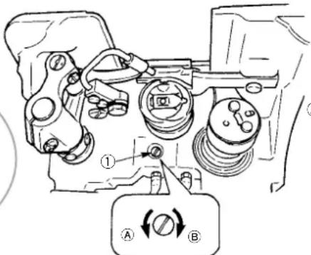
A = Decrease /
少 /
Verringern /
Diminution /
Disminuir /
Diminuzione /
Azalir /
меньшение
B = Increase /
多 /
Vergrößen /
Augmentation /
Aumentar /
Aumento /
Artar /
Увеличение

AVISO :
natural_image
Line drawing of a sewing machine needle and clasp mechanism (no text or symbols)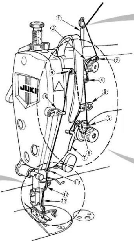

WARNING :
Turn OFF the power before starting the work so as to prevent accidents caused by abrupt start of the sewing machine.

注意:
(1) Adjusting the needle thread tension
Turn thread tension No. 1 nut ① clockwise (in direction A), to shorten the thread length remaining on the needle after thread trimming or counterclockwise (in direction B), to lengthen the thread length.
2) Turn thread tension nut No. 2 ② clockwise (in direction C) to increase or counterclockwise (in direction D) to reduce the needle thread tension.
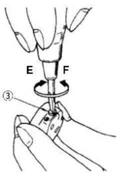
(2) Adjusting the bobbin thread tension
1) Turn tension adjusting screw ③ clockwise (in direction E) to increase or counterclockwise (in direction F) to reduce the bobbin thread tension.
(1) 上线张力的调节
natural_image
Diagram showing a gray arrow pointing to a circular diagram with a mechanical component (no text or symbols)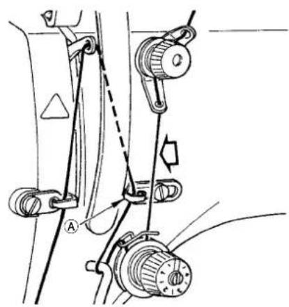
natural_image
Mechanical linkage diagram showing components like pulleys, springs, and a valve (no text or labels)(Note) Do not pass this thread through section A.
(注)不能把此线穿过①部
1) Insert the bobbin deep into the bobbin winder spindle ① until it will go no further.
2) Pass the bobbin thread pulled out from the spool rested on the right side of the thread stand following the order as shown in the figure on the left. Then, wind clockwise the end of the bobbin thread on the bobbin several times.
(In case of the aluminum bobbin, after winding clockwise the end of the bobbin thread, wind counterclockwise the thread coming from the bobbin thread tension several times to wind the bobbin thread with ease.)
3) Press the bobbin winder trip latch ② in the direction of A and start the sewing machine. The bobbin rotates in the direction of C and the bobbin thread is wound up. The bobbin winder spindle ① automatically as soon as the winding is finished.
4) Remove the bobbin and cut the bobbin thread with the thread cut retainer ③.
5) When adjusting the winding amount of the bobbin thread, loosen setscrew ④ and move bobbin winding lever ② to the direction of A or B. Then tighten setscrew ④.
To the direction of A: Decrease
To the direction of B: Increase
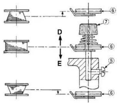
6) In case that the bobbin thread is not wound evenly on the bobbin, remove the handwheel, loosen screw ⑤ and adjust the height of bobbin thread tension ⑧.
- It is the standard that the center of the bobbin is as high as the center of thread tension disk ⑥.
- Adjust the position of thread tension disk ⑥ to the direction of D when the winding amount of the bobbin thread on the lower part of the bobbin is excessive and to the direction E when the winding amount of the bobbin thread on the upper part of the bobbin is excessive.
After the adjustment, tighten screw⑤.
7) To adjust the tension of the bobbin winder, turn the thread tension nut (Caution)
1. When winding the bobbin thread, start the winding in the state that the thread between the bobbin and thread tension disk ⑥ is tense.
2. When winding the bobbin thread in the state that sewing is not performed, remove the needle thread from the thread path of thread take-up and remove the bobbin from the hook.
3. There is the possibility that the thread pulled out from the thread stand is loosened due to the influence (direction) of the wind and may be entangled in the handwheel. Be careful of the direction of the wind.
Turn OFF the power before starting the work so as to prevent accidents caused by abrupt start of the sewing machine.
1) Loosen nut ②. As you turn presser spring regulator ① clockwise (in direction A), the presser foot pressure will be increased.
2) As you turn the presser spring regulator counter-clockwise (in direction ⑧), the pressure will be decreased.
3) After adjustment, tighten nut ②.
The standard value of the addition © of the height of presser spring regulator is as follows :
• S type : 31.5 to 29 mm
(Approximately 40 to 45N/4 to 4.5kg)
• H type : 31.5 to 28 mm
(Approximately 50 to 60N/5 to 6kg)
• A type : 22 mm (Approximately 20N/2kg)

注意:
* The dial calibration is in millimeters.
1) Turn stitch length dial ① in the direction of the arrow, and align the desired number to marker dot Ⓐ on the machine arm.
2) When you want to decrease the stitch length, turn stitch length dial ① while pressing feed lever ② in the direction of the arrow.
* 刻度盘的数字为 mm。
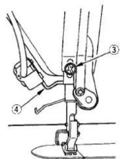
(1) Adjusting the stroke of thread take-up spring ①
1) Loosen setscrew ②.
2) Turn tension post ③ clockwise (in direction A), the stroke of the thread take-up spring will be increased, and turn the post ③ counterclockwise (in direction B), the stroke will be decreased.
(2) Adjusting the pressure of thread take-up spring ①
1) Loosen setscrew ②, and remove thread tension (asm.) ⑤.
2) Loosen tension post setscrew ④.
3) Turn tension post ③ clockwise (in direction A), the pressure will be increased, and turn the post ③ counterclockwise (in direction B), the pressure will be decreased.
* Standard state of the thread take-up spring
The engraved marker line ⑥ on the machine arm is almost aligned with the top of thread take-up spring. (It is necessary to adjust in accordance with materials and processes.)
(Caution) For the Model DDL-9000A-DS, the fully-dry hook is adopted. Comparing with the sewing machine using the existing hook, the sewing machine tends to be affected by the adjustment of the thread take-up spring. If the thread take-up spring does not work sufficiently, thread running increases. As a result, thread breakage, balloon stitching, etc. may occur.
To judge the work of the thread take-up spring, confirm whether or not the thread take-up spring works up to the last before needle thread is pulled out from E when pulling out needle thread in the direction of F after the pressure of the thread take-up spring has been performed. (State of G) When it does not work up to the last, decrease the pressure of the thread take-up spring. (State of H) In addition, the stroke of the thread take-up spring is excessively small, the spring does not work properly.
For the general fabrics, a stroke of 10 to 13 mm is proper.
(3) Adjusting The Thread Take-up Stroke
1) When sewing heavy-weight materials, move thread guide ⑧ to the left (in direction C) to increase the length of thread pulled out by the thread take-up.
2) When sewing light-weight materials, move thread guide ⑧ to the right (in direction D) to decrease the length of thread pulled out by the thread take-up
* Standard state of the thread guide The engraved marker line on the machine arm is aligned with engraved marker line on the thread guide ⑨ in the center.
(1) 调整挑线弹簧 ① 的行程量
1) 拧松线张力台固定螺丝 ②。
![[DDL-9000A-ΔS, -ΔA] ⑨ ⑧ C D ⑥ ① A B ③ ②](/content/2026/04/591709/images/1172ac616f403db75d888027fa6c347f043c1ecb371968f13d8117f17cfa7b6e.jpg)
![[DDL-9000A-SH] ⑨ ⑥ ① ③ ② A B](/content/2026/04/591709/images/1b9bee3f7e4047a18c1df11eb285b0270560a937e29fec4e890082e01044723d.jpg)
(1) Para ajustar el recorrido del muelle tira-hilo ①
- Turn OFF the power before starting the work so as to prevent accidents caused by abrupt start of the sewing machine.
- Do not perform switch operations other than those described in the following explanations.
- Be sure to re-turn the power switch ON after one second or more has passed. If the power is turned ON immediately after turning it OFF, the sewing machine may not work normally. In this case, turn ON the power again.
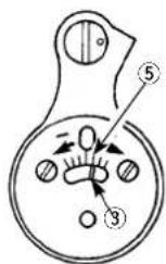
(1) Stop position after thread trimming
1) The standard needle stop position is obtained by aligning marker dot A on the pulley cover with white marker dot B on the handwheel
* For the details, refer to the Instruction Manual for the control box together.
(2) Adjusting procedure of the needle up/down stop position
1) Turn OFF the power to the machine.
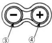
2) Pressing "+" switch ④ of the control box, turn ON the power to the machine.
3) Screen display is set to setting No. 96 and the number of revolutions is displayed. (When the screen display is not changed, operate again steps 1) and 2).
4) Specify the setting No. E with switch ① or switch ②.
Setting No. 121 : Needle UP stop position Setting No. 122 : Needle DOWN stop posit
5) Specify the setting contents F within the range of -15 to 15 with switch ③ or switch ④.
(Standard is "0". The numeric of set value indicates the approximate rotating angle. (When the numeric is set to the "+" direction, the needle UP stop position is lowered. (Direction C)
When the numeric is set to "-" direction, the needle UP stop position is raised. (Direction D)
6) After completion of the setting, press switch ① or switch ② to determine the updated value. (When turning OFF the power to the machine before performing this work, the contents are not updated.)
7) After completion of the operation, turn OFF the power to the machine. The normal operation can be performed by turning ON the power to the machine again.

注意:

AVISO :
Turn OFF the power before starting the work so as to prevent accidents caused by abrupt start of the sewing machine.
(1) Adjusting the pressure required to depress the front part of the pedal The pressure will be decreased when pedaling pressure adjust spring ① is placed on the left-hand side, and will be increased when it is placed on the right-hand side.
(2) Adjusting the pressure required to depress the back part of the pedal The pressure increases as you turn reverse depressing regulator screw ② in, and decreases as you turn the screw out.
(3) Adjusting the pedal stroke The pedal stroke decreases when you insert connecting rod ③ into the left hole ④.

注意:
17. ADJUSTMENT OF THE PEDAL /
踏板的调整 /
PEDALEINSTELLUNG /
REGLAGE DE LA PEDALE /
AJUSTE DEL PEDAL /
Turn OFF the power before starting the work so as to prevent accidents caused by abrupt start of the sewing machine.
(1) Installing the connecting rod
1) Move pedal ① to the right or left as illustrated by the arrows so that motor control lever ② and connecting rod ③ are straightened.
(2) Adjusting the pedal angle
1) The pedal tilt can be freely adjusted by changing the length of the connecting rod.
2) Loosen adjust screw ④, and adjust the length of connecting rod ②.

注意:

AVISO :
The pedal is operated in the following four steps:
1) The machine runs at low sewing speed when you lightly depress the front part of the pedal. Ⓑ
2) The machine runs at high sewing speed when you further depress the front part of the pedal. (If the automatic reverse feed stiehing has been preset, the machine runs at high speed after it completes reverse feed stitching.)
3) The machine stops (with its needle up or down) when you reset the pedal toits original position. ©
4) The machine trims threads when you fully depress the back part of the pedal.
* If your machine is provided with the Auto-lifter (AK138), an addition step is given between the machine stop and thread trimming step.
The presser foot goes up when you lightly depress the back part of the pedal Ⓓ, and if you further depress the back part, the thread trimmer is actuated.
When starting sewing from the state that the presser foot has been lifted with the Auto-lifter and you depress the back part of the pedal, the presser foot only comes down.
- If you reset the pedal to its neutral position during the automatic reverse feed stitching at seam start, the machine stops after it completes the reverse feed stitching.
- The machine will perform normal thread trimming even if you depress the back part of the pedal immediately following high or low speed sewing.
- The machine will completely perform thread trimming even if you reset the pedal to its neutral position immediately after the machine started thread trimming action.
踏板有 4 级操作。
flowchart
graph TD
    A["Step A: Hand joints"] --> B["Step B: Trigger mechanism"]
    B --> C["Step C: Trigger mechanism"]
    C --> D["Step D: Trigger mechanism"]
    D --> E["Step E: Trigger mechanism"]
Turn OFF the power before starting the work so as to prevent accidents caused by abrupt start of the sewing machine.
Adjust the timing between the needle and the hook as follows :
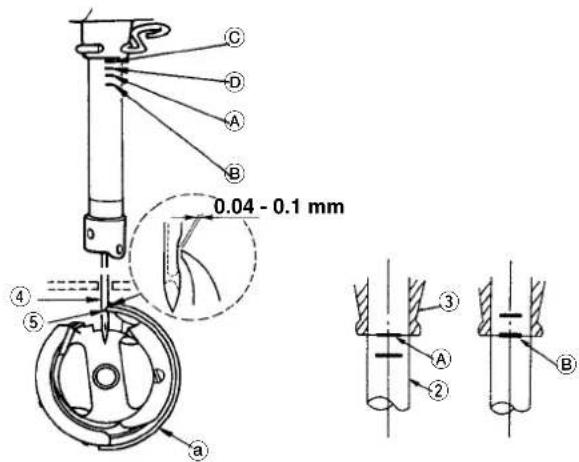
1) Adjusting the needle bar height. Turn the handwheel to bright the needle bar down to the lowest point of its stroke, and loosen setscrew ①.
2) Adjusting the needle bar height. Align marker line (For a DB needle : marker line Ⓐ, For a DA needle : marker line Ⓑ) on needle bar ② with the bottom end of needle bar lower bushing ③, then tighten setscrew ①.
3) Position the needle and the hook ⓐ.
Loosen the three hook setscrews, turn the handwheel in normal rotation and align marker line (For a DB needle : marker line Ⓑ, For a DA needle : marker line Ⓞ) on ascending needle bar ② with the bottom end of needle bar lower bushing ③.
4) In this state, align hook blade point ⑤ with the center of needle ④. Provide a clearance of 0.04 mm to 0.1 mm (reference value) between the needle and the hook, then securely tighten the three hook setscrews.
(Caution) If the clearance between the blade point of hook and the needle is smaller than the specified value, the blade point of hook will be damaged. If the clearance is larger, stitch skipping will result.
- RP hook (dry hook) is used for the hook of DDL-9000A-DS type. When replacing, use the part No. described below. There are two kinds of Part Nos. of the hooks classified by the regions. 22890206
(Caution) Periodically clean RP hook (dry hook) since the hook rolls up thread waste or cloth waste and failure of the machine or defective sewing may be caused.

注意:

AVISO :
natural_image
Technical line drawing of a sewing machine needle and foot (no text or symbols)Turn OFF the power before starting the work so as to prevent accidents caused by abrupt start of the sewing machine.
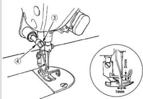
Adjust the position of the wiper according to the thickness of the material sewn.
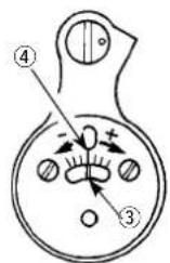
1) Turn the handwheel in the normal direction of rotation to align white marker dot ① on the handwheel with marker dot ② on the machine arm.
2) Adjust the distance between the flat part of the wiper ⑥ and the center of the needle to 1 mm. Tighten wiper adjust screw ③ so that the wiper is pressed and fixed by wiper collar ④.
* When the wiper is unnecessary, turn wiper switch ⑤ OFF.

注意:
Turn OFF the power before starting the work so as to prevent accidents caused by abrupt start of the sewing machine.
It is possible to change the stitch length of the normal feed pitch by operating switch ① or reverse feed control lever
② during sewing.
1) Tilt the machine head and adjust feed dial ③ to the condensed stitch length. The stitch length adjustment value can be around "0" to 1.
2) Loosen setscrew ⑤ in condensation stopper ④ and slide the stopper in the direction of the arrow mark to adjust so that it comes in contact with the end of reverse feed solenoid ⑥. Then fix it with setscrew ⑤.
3) When setting the state to the initial state (release), fix it at the position of the center of ⑤ and the engraved marker line of ④.

注意:

AVISO :
(b) Center of needle
a 移动刀
⑥ 机针中心
a Schwingmesser
b Nadelmitte
a Couteau mobile
b Axe de l'aiguille
a Cuchilla móvil
⑥ Centro de aguja
① Coltello mobile
⑥ Centro dell'ago
a Hareketli bıçak
⑥ Iğnenin ortası
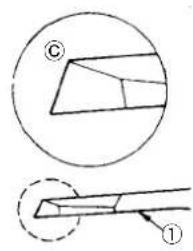
Turn OFF the power before starting the work so as to prevent accidents caused by abrupt start of the sewing machine.
When the knife sharpness has deteriorated, sharpen again counter knife ① as illustrated in Ⓒ, and properly reinstall it.
1) If the mounting position of the counter knife is moved in direction ① from the standard mounting position, the thread length after thread trimming will be increased accordingly.
2) If the mounting position is moved in direction ⑧, the thread length will be decreased accordingly.
(Caution) When sharpening again the knife blade, extra special care must be taken on the handling of the knife.

注意:
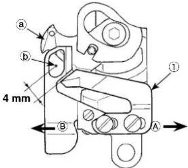
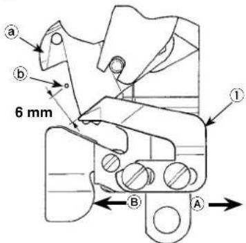
Turn OFF the power before starting the work so as to prevent accidents caused by abrupt start of the sewing machine.
The amount of reverse feed has been regulated to 4mm at the time of delivery and release the regulation with the procedures below when using the machine with the amount more than the value.
1) Adjust feed dial ③ to the amount of reverse feed used.
2) Tilt the machine head and loosen two setscrews ⑤ in reverse feed solenoid ④.
3) Adjust the position of reverse feed solenoid ④ so that plunger rubber ⑥ lightly turns in the state that reverse feed control lever ② is pressed.
(Caution) When performing the reverse feed stitching (① and ②) after releasing the regulation, decrease the sewing speed.

注意:
[DDL-9000A-SS, -DS, -M △]
[DDL-9000A-SH]

AVISO :

AVISO :
Feed dog at the time of delivery /
出货送布牙 /
Position of engraved marker dot of feed bar rocker shaft /
水平传送座轴的刻点位置
Turn OFF the power before starting the work so as to prevent accidents caused by abrupt start of the sewing machine.
(1) Standard value of the height of the feed dog
Standard feed dog height, when it is lifted to the highest from the top surface of the throat plate, :
9000A-S and 9000A-A: 0.8 mm 9000A-SH : 1.2 mm
Adjust the feed dog height in accordance with processes and materials.
(Caution) Adjust the directions of the engraved marker dot of feed bar driving shaft ① and the engraved marker dot of feed bar rocker shaft ③ on the right side (operator side).
(2) Adjusting the height and tilt of the feed dog
1) Loosen setscrew ② in feed bar driving shaft ① and setscrew ④ in feed bar rocker shaft ③.
2) Height and tilt of the feed dog will change by turning both shafts ① and ② with a screwdriver.
3) For the relation between the rotating direction of each shaft and tilt of feed bar ⑥, refer to the figure above.
* Standard delivery state : The engraved marker dot of feed bar rocker shaft ③ is adjusted to engraved marker line ⑦ of the feed dog of each type and the height of feed dog is adjusted with feed bar driving shaft ①.
4) After the adjustment, securely tighten the setscrews. (Tighten setscrews ② and ④ in the state that shafts ① and ③ are pushed against the handwheel side.)
(Caution)
-
If the tilt of the feed dog is adjusted with one shaft only, the height of the feed dog changes. Be sure to adjust it with both shafts.
-
Movement position of the feed dog may be shifted depending on the adjusting position of the shaft. At this time, loosen setscrew ⑤ in feed rocker shaft arm ⑦ and adjust the movement position.
-
The feed dog may interfere with the thread trimmer unit due to the adjustment of height or tilt of the feed dog. So, be careful.

注意:
Turn OFF the power before starting the work so as to prevent accidents caused by abrupt start of the sewing machine.
Timing of the feed dog can be adjusted by changing the stop position of feed eccentric cam①. Adjusting procedure is as described below.
1) Tilt the sewing machine head and loosen two setscrews ① in feed eccentric cam ②.
2) Turn feed eccentric cam ① to change the timing of the feed dog. Align graduation ③ on the feed bar driving arm with engraved marker line ④ on the feed driving shaft.
- Turn feed eccentric cam ① in the direction of (+)
→ Increases the feed timing. - Turn feed eccentric cam ① in the direction of ( - )
→ Decreases the feed timing.
* Standard value of the engraved marker line on the feed eccentric cam
The position of graduation ③ in the standard state :
9000A- △S and 9000A-△A : Engraved marker line ④
9000A-SH : Engraved marker line ⑤ (+10°)

注意:
DDL-9000A-*S
DDL-9000A-MA
DDL-9000A-SH
AVISO :
Turn OFF the power before starting the work so as to prevent accidents caused by abrupt start of the sewing machine.
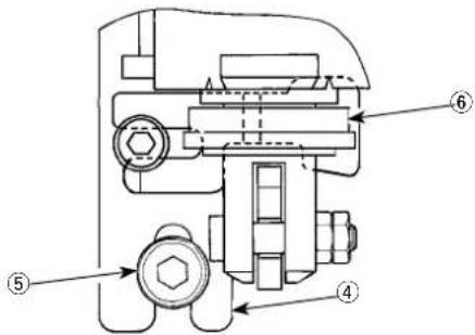
By means of the thread tension release releasing mechanism, sewing can be performed without slackening the needle thread tension even when the presser foot is lifted during sewing. (Even when the presser foot is slightly lifted at the thick overlapped section by the knee lifter, this mechanism can prevent the thread tension from being changed.
(1) How to release
1) Remove the cap in the machine head and loosen thread tension release changeover screw ① using a hexagon wrench.
2) Fix screw ① on the top of thread tension release changeover plate ②.
The thread tension disk does not rise even when the presser foot is lifted, and the needle thread tension is not loosened. (The thread tension disk rises only when thread trimming is performed.)
(Caution) Do not use screw ① at any position other than the top or bottom position of the thread tension release changeover plate.
* The screw has been factory-set to the bottom position at the time of delivery.
* In case of the machine with wiper, remove the wiper unit (two setscrews) to adjust.

注意:

AVISO :
Turn OFF the power before starting the work so as to prevent accidents caused by abrupt start of the sewing machine.
When sewing velvet or the like which is fluffy, slippage of material or damage of material is reduced by using screw ① for presser foot micro-lifting. Lower the presser foot and set the state that the feed dog is lower than the throat plate. Gradually tighten screw ① for presser foot micro-lifting in the state that nut ② is loosened, finely adjust the position of the presser foot until it matches the material, and fix it with nut ②.
(Caution) When the presser foot micro-lifting mechanism is not used, adjust the height of screw ① so that it is higher by approximately 9mm than the sewing machine. If the sewing machine is operated in the state that the micro-lifting mechanism is working, sufficient feed force cannot be obtained.

注意:
Presser foot micro-lifter (asm.) [23611056] (Separately available) /
微量压脚提升装置(组件)〔23611056〕(另购)/
For DDL-9000A, the presser foot micro-lifting mechanism is provided as standard. When it is frequently used, however, it is convenient to use the micro-lifting device (separately available) which can be adjusted without using tools.
Presser foot micro-lifter components
| No. | Part No. | Description | Q'ty |
| 1 | 23611106 Hand lfter | 1 | |
| 2 | 23610504 | Stopper base | 1 |
| 3 | 23610652 | Stopper screw | 1 |
| 4 | D5119206KOK | Collar | 2 |
| 5 | 23610702 | Nut | 1 |
| 6 | SL6053592TN | Setscrew | 1 |
natural_image
Technical line drawing of a mechanical component with mounting holes and a hexagonal opening (no text or symbols)22908552
Hand lifter cam (mounted on the machine head is used) / 压脚提升凸轮(机头安装配件)/
Turn OFF the power before starting the work so as to prevent accidents caused by abrupt start of the sewing machine.
When using the machine at the sewing speed more than that at the time of delivery (more than 4,000 rpm), slide upward the position of feed conversion shaft spring hook ① and adjust for use. A : Sewing speed at the time of delivery (less than 4,000 rpm)
B : More than 4,000 rpm

注意:

WARNING :
Turn OFF the power before starting the work so as to prevent accidents caused by abrupt start of the sewing machine.
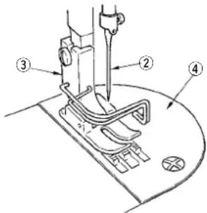
Perform the maintenance below every day for longer use of your machine. (1) Confirmation of the amount of oil in the hook oil tank.
Confirm that the top of oil amount indicating rod ① is between the upper engraved marker line and the lower engraved marker line of the oil amount indicating window. (For the details, refer to "4. LUBRICATION".)
(2) Cleaning
1) Remove needle ②, presser foot ③ and throat plate ④.
2) Remove dust adhered to feed dog ⑥ and thread trimmer unit ⑤ with a soft brush or cloth.
3) Tilt the machine head and wipe out the dirt of bobbin case and the like with soft cloth, and confirm that there is no scratch. Wipe out with the cloth dust and hook oil drained in the under cover near the hook.

注意:
natural_image
Line drawing of a mechanical assembly with hands operating a component (no text or symbols)
AVISO :
Copyright © 2006-2007 JUKI CORPORATION
- All rights reserved throughout the world.
Please do not hesitate to contact our distributors or agents in your area for further information when necessary.
* The description covered in this instruction manual is subject to change for improvement of the commodity without notice.