ARXP35M - Air Conditioning DAIKIN - Free user manual and instructions
Find the device manual for free ARXP35M DAIKIN in PDF.
Download the instructions for your Air Conditioning in PDF format for free! Find your manual ARXP35M - DAIKIN and take your electronic device back in hand. On this page are published all the documents necessary for the use of your device. ARXP35M by DAIKIN.
USER MANUAL ARXP35M DAIKIN
2.1.2 To remove the accessories from the outdoor unit....... 4
3.1.1 Installation site requirements of the outdoor unit ........ 4
3.1.2 Additional installation site requirements of the
3.2.2 Refrigerant piping length and height difference .......... 5
4.2.4 To prevent the outdoor unit from falling over .............. 6
4.3.2 Precautions when connecting the refrigerant piping... 7
4.3.3 To connect the refrigerant piping to the outdoor unit .. 7
5.2 Checklist during commissioning ................................................ 10
6.3.2 To start/stop forced cooling using the indoor unit
INFORMATION Make sure that the user has the printed documentation and ask him/her to keep it for future reference. Target audience Authorised installers Documentation set This document is part of a documentation set. The complete set consists of:
- General safety precautions:
- Safety instructions that you MUST read before installing
- Format: Paper (in the box of the outdoor unit)
- Outdoor unit installation manual:
- Installation instructions
- Format: Paper (in the box of the outdoor unit)
- Installer reference guide:
- Preparation of the installation, reference data,…
- Format: Digital files on http://www.daikineurope.com/support- and-manuals/product-information/ Latest revisions of the supplied documentation may be available on the regional Daikin website or via your dealer. The original documentation is written in English. All other languages are translations. Technical engineering data
- A subset of the latest technical data is available on the regional Daikin website (publicly accessible).
- The full set of latest technical data is available on the Daikin extranet (authentication required). 2 About the box
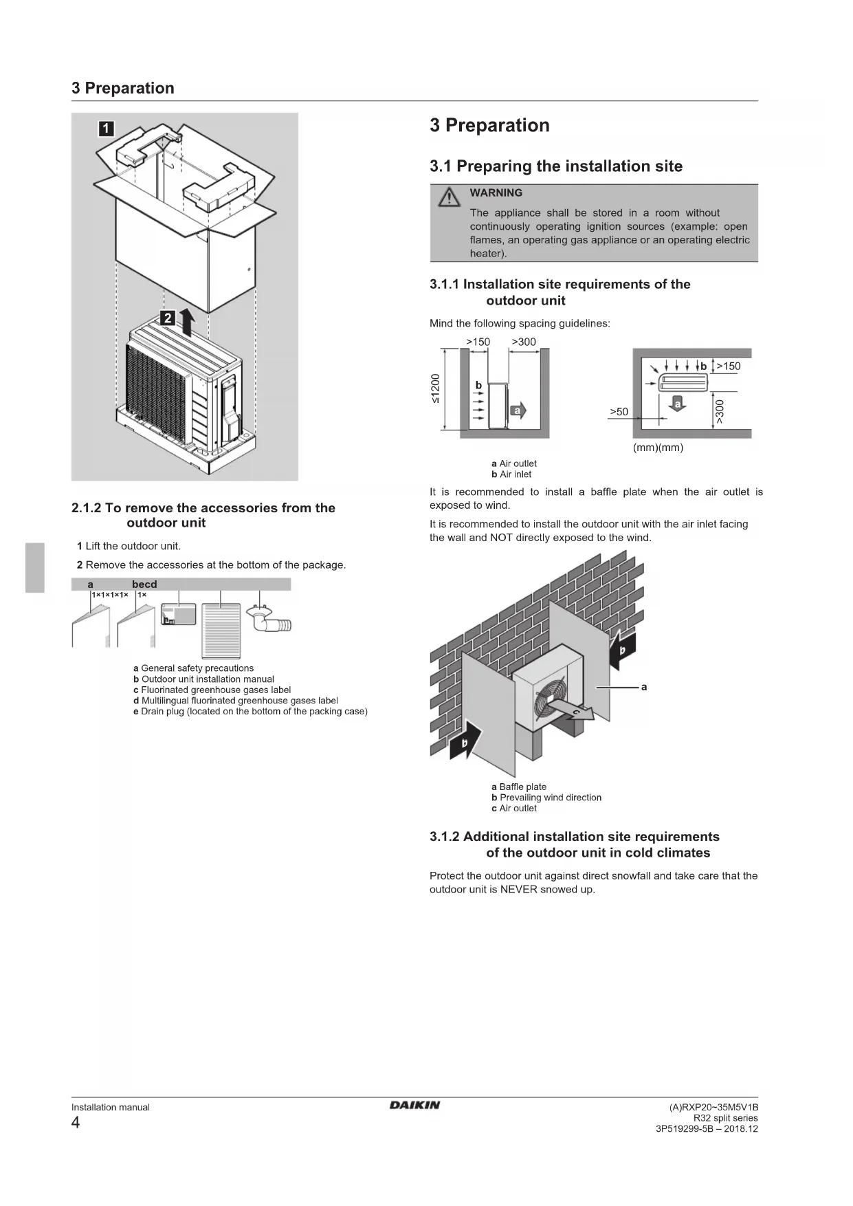
2.1.1 To unpack the outdoor unit3 Preparation
2.1.2 To remove the accessories from the
outdoor unit 1 Lift the outdoor unit.2 Remove the accessories at the bottom of the package. b ec d
1× 1× 1× 1× a General safety precautionsb Outdoor unit installation manualc Fluorinated greenhouse gases labeld Multilingual fluorinated greenhouse gases labele Drain plug (located on the bottom of the packing case) 3 Preparation
3.1 Preparing the installation site
WARNINGThe appliance shall be stored in a room withoutcontinuously operating ignition sources (example: openflames, an operating gas appliance or an operating electricheater).
3.1.1 Installation site requirements of the
outdoor unit Mind the following spacing guidelines: ≤1200>150 >150>50>300 >300(mm)(mm)
a Air outletb Air inletIt is recommended to install a baffle plate when the air outlet isexposed to wind.It is recommended to install the outdoor unit with the air inlet facingthe wall and NOT directly exposed to the wind.
a Baffle plateb Prevailing wind directionc Air outlet
3.1.2 Additional installation site requirements
of the outdoor unit in cold climates Protect the outdoor unit against direct snowfall and take care that theoutdoor unit is NEVER snowed up.4 Installation Installation manual (A)RXP20~35M5V1BR32 split series3P519299-5B – 2018.12
a Snow cover or shedb Pedestalc Prevailing wind directiond Air outletIn any case, provide at least 300mm of free space below the unit.Additionally, make sure the unit is positioned at least 100mm abovethe maximum expected level of snow. See "4.2 Mounting theoutdoor unit"on page5 for more details.In heavy snowfall areas it is very important to select an installationsite where the snow will NOT affect the unit. If lateral snowfall ispossible, make sure that the heat exchanger coil is NOT affected bythe snow. If necessary, install a snow cover or shed and a pedestal.See also2 4.2 Mounting the outdoor unit [}5]
3.2 Preparing refrigerant piping
3.2.1 Refrigerant piping requirements
- Piping material: Phosphoric acid deoxidised seamless copper.▪ Piping diameter:Liquid piping Ø6.4mm (1/4")Gas piping Ø9.5mm (3/8")▪ Piping temper grade and thickness:Outer diameter (Ø) Temper grade Thickness (t) (a) 6.4mm (1/4") Annealed (O) ≥0.8mm
9.5mm (3/8") Annealed (O)(a) Depending on the applicable legislation and the unit'smaximum working pressure (see "PS High" on the unitname plate), larger piping thickness might be required.
3.2.2 Refrigerant piping length and height
difference What? DistanceMaximum allowable pipe length 15mMinimum allowable pipe length 1.5mMaximum allowable height difference 12m
3.2.3 Refrigerant piping insulation
Insulation thickness (t) 6.4mm (1/4") 8~10mm ≥10mm9.5mm (3/8") 12~15mm
If the temperature is higher than 30°C and the humidity is higherthan RH80%, the thickness of the insulation materials should be at least 20 mm to prevent condensation on the surface of the insulation. 4 Installation
4.1 Opening the units
4.1.1 To open the outdoor unit
4.2 Mounting the outdoor unit
4.2.1 To provide the installation structure
Prepare 4 sets of M8 or M10 anchor bolts, nuts and washers (fieldsupply). 20 mm4 Installation Installation manual (A)RXP20~35M5V1BR32 split series3P519299-5B – 2018.12
>300 In any case, provide at least 300mm of free space below the unit.Additionally, make sure the unit is positioned at least 100mm abovethe maximum expected level of snow. In this case, it isrecommended to construct a pedestal.
4.2.2 To install the outdoor unit
4.2.3 To provide drainage
NOTICE If the unit is installed in a cold climate, take adequate measures so that the evacuated condensate CANNOTfreeze.INFORMATIONFor information on the available options, contact yourdealer.NOTICE Provide at least 300 mm of free space below the unit. Additionally, make sure the unit is positioned at least100mm above the expected level of snow.1 Use a drain plug for drainage.2 Use a Ø16mm hose (field supply).
a Drain portb Bottom framec Drain plugd Hose (field supply)
4.2.4 To prevent the outdoor unit from falling
over In case the unit is installed in places where strong wind can tilt theunit, take following measure:1 Prepare 2 cables as indicated in the following illustration (fieldsupply).2 Place the 2 cables over the outdoor unit.3 Insert a rubber sheet between the cables and the outdoor unitto prevent the cables from scratching the paint (field supply).4 Attach the ends of the cables and tighten them.
4.3 Connecting the refrigerant piping
DANGER: RISK OF BURNING
4.3.1 About connecting the refrigerant piping
Before connecting the refrigerant pipingMake sure the outdoor and indoor unit are mounted.Typical workflowConnecting the refrigerant piping involves:▪ Connecting the refrigerant piping to the indoor unit▪ Connecting the refrigerant piping to the outdoor unit▪ Insulating the refrigerant piping▪ Keeping in mind the guidelines for:▪ Pipe bending▪ Flaring pipe ends▪ Using the stop valves4 Installation Installation manual
R32 split series 3P519299-5B – 2018.12
4.3.2 Precautions when connecting the
- To prevent gas leakage, apply refrigeration oil only to the inside of the flare. Use refrigeration oil for R32.
- Do NOT reuse joints. WARNING Connect the refrigerant piping securely before running the compressor. If the refrigerant piping is NOT connected and the stop valve is open when the compressor is run, air will be sucked in. This will cause abnormal pressure in the refrigeration cycle, which may result in equipment damage and even injury.
4.3.3 To connect the refrigerant piping to the
- Piping length. Keep field piping as short as possible.
- Piping protection. Protect the field piping against physical damage. 1 Connect the liquid refrigerant connection from the indoor unit to the liquid stop valve of the outdoor unit.
a Liquid stop valve b Gas stop valve c Service port 2 Connect the gas refrigerant connection from the indoor unit to the gas stop valve of the outdoor unit. NOTICE It is recommended that the refrigerant piping between indoor and outdoor unit is installed in a ducting or the refrigerant piping is wrapped with finishing tape.
NOTICE Do NOT exceed the unit's maximum working pressure (see "PS High" on the unit name plate). NOTICE Make sure to use a recommended bubble test solution from your wholesaler. Do not use soap water, which may cause cracking of flare nuts (soap water may contain salt, which absorbs moisture that will freeze when the piping gets cold), and/or lead to corrosion of flared joints (soap water may contain ammonia which causes a corrosive effect between the brass flare nut and the copper flare). 1 Charge the system with nitrogen gas up to a gauge pressure of at least 200 kPa (2 bar). It is recommended to pressurize to 3000kPa (30bar) in order to detect small leaks. 2 Check for leaks by applying the bubble test solution to all connections. 3 Discharge all nitrogen gas.
4.4.2 To perform vacuum drying
1 Vacuum the system until the pressure on the manifold indicates −0.1MPa (−1bar). 2 Leave as is for 4-5minutes and check the pressure: If the pressure… Then… Does not change There is no moisture in the system. This procedure is finished. Increases There is moisture in the system. Go to the next step. 3 Vacuum the system for at least 2hours to a manifold pressure of −0.1MPa (−1bar). 4 After turning the pump OFF, check the pressure for at least 1hour. 5 If you do NOT reach the target vacuum or CANNOT maintain the vacuum for 1hour, do the following:
- Check for leaks again.
- Perform vacuum drying again. NOTICE Make sure to open the stop valves after installing the refrigerant piping and performing vacuum drying. Running the system with the stop valves closed may break the compressor.
The outdoor unit is factory charged with refrigerant, but in some cases the following might be necessary: What When Charging additional refrigerant When the total liquid piping length is more than specified (see later). Completely recharging refrigerant Example:
- When relocating the system.
- After a leak.4 Installation Installation manual
R32 split series 3P519299-5B – 2018.12 Charging additional refrigerant Before charging additional refrigerant, make sure the outdoor unit's external refrigerant piping is checked (leak test, vacuum drying). INFORMATION Depending on the units and/or the installation conditions, it might be necessary to connect electrical wiring before you can charge refrigerant. Typical workflow – Charging additional refrigerant typically consists of the following stages: 1 Determining if and how much you have to charge additionally. 2 If necessary, charging additional refrigerant. 3 Filling in the fluorinated greenhouse gases label, and fixing it to the inside of the outdoor unit. Completely recharging refrigerant Before completely recharging refrigerant, make sure the following is done: 1 All refrigerant is recovered from the system. 2 The outdoor unit's external refrigerant piping is checked (leak test, vacuum drying). 3 Vacuum drying on the outdoor unit's internal refrigerant piping is performed. NOTICE Before completely recharging, perform vacuum drying on the outdoor unit's internal refrigerant piping as well. Typical workflow – Completely recharging refrigerant typically consists of the following stages: 1 Determining how much refrigerant to charge. 2 Charging refrigerant. 3 Filling in the fluorinated greenhouse gases label, and fixing it to the inside of the outdoor unit.
4.5.2 About the refrigerant
This product contains fluorinated greenhouse gases. Do NOT vent gases into the atmosphere. Refrigerant type: R32 Global warming potential (GWP) value: 675 NOTICE In Europe, the greenhouse gas emissions of the total refrigerant charge in the system (expressed as tonnes CO
equivalent) is used to determine the maintenance intervals. Follow the applicable legislation. Formula to calculate the greenhouse gas emissions: GWP value of the refrigerant × Total refrigerant charge [in kg] / 1000 Please contact your installer for more information.
WARNING: FLAMMABLE MATERIAL
The refrigerant inside this unit is mildly flammable. WARNING The appliance shall be stored in a room without continuously operating ignition sources (example: open flames, an operating gas appliance or an operating electric heater). WARNING
- Do NOT pierce or burn refrigerant cycle parts.
- Do NOT use cleaning materials or means to accelerate the defrosting process other than those recommended by the manufacturer.
- Be aware that the refrigerant inside the system is odourless. WARNING The refrigerant inside the unit is mildly flammable, but normally does NOT leak. If the refrigerant leaks in the room and comes in contact with fire from a burner, a heater, or a cooker, this may result in fire, or the formation of a harmful gas. Turn off any combustible heating devices, ventilate the room, and contact the dealer where you purchased the unit. Do NOT use the unit until a service person confirms that the part from which the refrigerant leaked has been repaired.
4.5.3 To determine the additional refrigerant
amount If the total liquid piping length is… Then… ≤10m Do NOT add additional refrigerant. >10m R=(total length (m) of liquid piping–10m)×0.020 R=Additional charge (kg) (rounded in units of 0.01kg) INFORMATION Piping length is the one-way length of liquid piping.
4.5.4 To determine the complete recharge
amount INFORMATION If a complete recharge is necessary, the total refrigerant charge is: the factory refrigerant charge (see unit name plate) + the determined additional amount.
4.5.5 To charge additional refrigerant
- Only use R32 as refrigerant. Other substances may cause explosions and accidents.
- R32 contains fluorinated greenhouse gases. Its global warming potential (GWP) value is 675. Do NOT vent these gases into the atmosphere.
- When charging refrigerant, ALWAYS use protective gloves and safety glasses. Prerequisite: Before charging refrigerant, make sure the refrigerant piping is connected and checked (leak test and vacuum drying). 1 Connect the refrigerant cylinder to the service port. 2 Charge the additional refrigerant amount. 3 Open the gas stop valve.4 Installation Installation manual
R32 split series 3P519299-5B – 2018.12
4.5.6 To fix the fluorinated greenhouse gases
label 1 Fill in the label as follows:
Contains fluorinated greenhouse gases
a If a multilingual fluorinated greenhouse gases label is delivered with the unit (see accessories), peel off the applicable language and stick it on top of a. b Factory refrigerant charge: see unit name plate c Additional refrigerant amount charged d Total refrigerant charge e Greenhouse gas emissions of the total refrigerant charge expressed as tonnes CO
equivalent f GWP = Global warming potential NOTICE In Europe, the greenhouse gas emissions of the total refrigerant charge in the system (expressed as tonnes CO
equivalent) is used to determine the maintenance intervals. Follow the applicable legislation. Formula to calculate the greenhouse gas emissions: GWP value of the refrigerant × Total refrigerant charge [in kg] / 1000 2 Fix the label on the inside of the outdoor unit near the gas and liquid stop valves.
4.6 Connecting the electrical wiring
- All wiring MUST be performed by an authorised electrician and MUST comply with the applicable legislation.
- Make electrical connections to the fixed wiring.
- All components procured on-site and all electrical construction MUST comply with the applicable legislation. WARNING ALWAYS use multicore cable for power supply cables. WARNING If the supply cord is damaged, it MUST be replaced by the manufacturer, its service agent or similarly qualified persons in order to avoid a hazard. WARNING Do NOT connect the power supply to the indoor unit. This could result in electrical shock or fire. WARNING
- Do NOT use locally purchased electrical parts inside the product.
- Do NOT branch the power supply for the drain pump, etc. from the terminal block. This could result in electrical shock or fire. WARNING Keep the interconnection wiring away from copper pipes without thermal insulation as such pipes will be very hot.
4.6.1 Specifications of standard wiring
components Component Power supply cable Voltage 220~240V Phase 1~ Frequency 50Hz Wire sizes MUST comply with applicable legislation Interconnection cable (indoor↔outdoor) 4-core cable ≥1.5 mm² and applicable for 220~240 V Recommended field fuse 16A Earth leakage circuit breaker MUST comply with applicable legislation
4.6.2 To connect the electrical wiring on the
outdoor unit 1 Remove the service cover. 2 Open the wire clamp. 3 Connect the interconnection cable and power supply as follows: 50 Hz 220-240 V c d
a b e a Interconnection cable b Power supply cable c Circuit breaker d Earth leakage circuit breaker e Power supply f Earth 4 Tighten the terminal screws securely. We recommend using a Phillips screwdriver.5 Commissioning Installation manual (A)RXP20~35M5V1BR32 split series3P519299-5B – 2018.12
4.7 Finishing the outdoor unit
4.7.1 To finish the outdoor unit installation
1 Insulate and fix the refrigerant piping and interconnection cable as follows:
a Gas pipeb Gas pipe insulationc Interconnection cabled Liquid pipee Liquid pipe insulationf Finishing tape 2 Install the service cover.
4.7.2 To close the outdoor unit
NOTICE When closing the outdoor unit cover, make sure that the tightening torque does NOT exceed 1.3N•m.
5 Commissioning NOTICE NEVER operate the unit without thermistors and/or pressure sensors/switches. Burning of the compressor might result.
5.1 Checklist before commissioning
After the installation of the unit, first check the following items. Once all below checks are fulfilled, the unit MUST be closed, ONLY then can the unit be powered up. The indoor unit is properly mounted. The outdoor unit is properly mounted. The system is properly earthed and the earth terminals are tightened. The power supply voltage matches the voltage on the identification label of the unit. There are NO loose connections or damaged electrical components in the switchbox. There are NO damaged components or squeezed pipes on the inside of the indoor and outdoor units. There are NO refrigerant leaks. The refrigerant pipes (gas and liquid) are thermally insulated. The correct pipe size is installed and the pipes are properly insulated. The stop valves (gas and liquid) on the outdoor unit are fully open. The following field wiring has been carried out according to this document and the applicable legislation between the outdoor unit and the indoor unit. Drainage Make sure drainage flows smoothly. Possible consequence: Condensate water might drip. The indoor unit receives the signals of the user interface. The specified wires are used for the interconnection cable. The fuses, circuit breakers, or locally installed protection devices are installed according to this document, and have NOT been bypassed.
5.2 Checklist during commissioning
To perform an air purge. To perform a test run.
5.3 To perform a test run
Prerequisite: Power supply MUST be in the specified range. Prerequisite: Test run may be performed in cooling or heating mode. Prerequisite: Test run should be performed in accordance with the operation manual of the indoor unit to make sure that all functions and parts are working properly. 1 In cooling mode, select the lowest programmable temperature. In heating mode, select the highest programmable temperature. Test run can be disabled if necessary. 2 When the test run is finished, set the temperature to a normal level. In cooling mode: 26~28°C, in heating mode: 20~24°C. 3 The system stops operating 3 minutes after the unit is turned OFF. INFORMATION
- Even if the unit is turned OFF, it consumes electricity.
- When the power turns back on after a power break, the previously selected mode will be resumed.
5.4 Starting up the outdoor unit
See the indoor unit installation manual for configuration and commissioning of the system.6 Disposal Installation manual (A)RXP20~35M5V1BR32 split series3P519299-5B – 2018.12 6 Disposal NOTICE Do NOT try to dismantle the system yourself: dismantling of the system, treatment of the refrigerant, oil and other parts MUST comply with applicable legislation. Units MUST be treated at a specialised treatment facility for reuse, recycling and recovery.
6.1 Overview: Disposal
Typical workflow Disposing of the system typically consists of the following stages: 1 Pumping down the system. 2 Bringing the system to a specialized treatment facility. INFORMATION For more details, see the service manual.
Pump down – Refrigerant leakage. If you want to pump down the system, and there is a leak in the refrigerant circuit:
- Do NOT use the unit's automatic pump down function, with which you can collect all refrigerant from the system into the outdoor unit. Possible consequence: Self-combustion and explosion of the compressor because of air going into the operating compressor.
- Use a separate recovery system so that the unit's compressor does NOT have to operate. NOTICE During pump down operation, stop the compressor before removing the refrigerant piping. If the compressor is still running and the stop valve is open during pump down, air will be sucked into the system. Compressor breakdown or damage to the system can result due to abnormal pressure in the refrigerant cycle. Pump down operation will extract all refrigerant from the system into the outdoor unit. 1 Remove the valve cap from the liquid stop valve and the gas stop valve. 2 Carry out forced cooling. See "6.3 To start and stop forced cooling"on page11. 3 After 5 to 10minutes (after only 1 or 2minutes in case of very low ambient temperatures (<−10°C)), close the liquid stop valve with a hexagonal wrench. 4 Check on the manifold if the vacuum is reached. 5 After 2-3 minutes, close the gas stop valve and stop forced cooling.
a Gas stop valveb Closing directionc Hexagonal wrenchd Valve cape Liquid stop valve
6.3 To start and stop forced cooling
There are 2methods to perform forced cooling.
- Method 1. Using the indoor unit ON/OFF switch (if present on the indoor unit).
- Method 2. Using the indoor unit user interface.
6.3.1 To start/stop forced cooling using the
indoor unit ON/OFF switch 1 Press the ON/OFF switch for at least 5seconds. Result: Operation will start. INFORMATION Forced cooling stops automatically after 15minutes. 2 To stop operation sooner, press the ON/OFF switch.
6.3.2 To start/stop forced cooling using the
indoor unit user interface 1 Set the operation mode to cooling. For the procedure, refer to "To perform a test run" in the installation manual of the indoor unit.7 Technical data Installation manual (A)RXP20~35M5V1BR32 split series3P519299-5B – 2018.12 7 Technical data A subset of the latest technical data is available on the regional Daikin website (publicly accessible). The full set of latest technical data is available on the Daikin Business Portal (authentication required).
PTC* : THERMISTOR PTC
Y*R, Y*S : REVERSING SOLENOID VALVE COIL
Isolationsdicke (t)6,4mm (1/4") 8~10mm ≥10mm9,5mm (3/8") 12~15mm
Contains fluorinated greenhouse gases
PTC* : THERMISTOR PTC
Épaisseur del'isolation (t)6,4mm (1/4") 8~10mm ≥10mm9,5mm (3/8") 12~15mm
Contains fluorinated greenhouse gases
WAARSCHUWING: ONTVLAMBAAR MATERIAAL
Contains fluorinated greenhouse gases
PTC* : PTC THERMISTOR
Contains fluorinated greenhouse gases
Contains fluorinated greenhouse gases
Contains fluorinated greenhouse gases
Contains fluorinated greenhouse gases
Contains fluorinated greenhouse gases
Contains fluorinated greenhouse gases