PC0968 - Compressor Senco - Free user manual and instructions
Find the device manual for free PC0968 Senco in PDF.

| Product Type | Air Compressor |
| Brand | Senco |
| Model | PC0968 |
| Dimensions (L x W x H) | 40 x 38 x 34 cm |
| Net Weight | 17.3 kg |
| Power Supply | 230 V ~ 50 Hz, 6 A, single phase |
| Motor Power | 0.54 kW |
| Motor Speed | 2850 RPM |
| Tank Capacity | 10 L (2.5 US gallons) |
| Maximum Pressure | 8.6 bar |
| Cut-Out Pressure (high) | 8.6 bar |
| Cut-In Pressure (low) | 6.2 bar |
| Air Displacement | 4 ft³/min |
| Effective Flow at 6.2 bar | 1.4 ft³/min |
| Sound Level | 79 dBA |
| Thermal Protection | Thermal cut-out switch with manual reset |
| Safety Valve | Yes, factory preset |
| Pressure Regulator | Yes, with discharge pressure gauge |
| Air Filter | Washable foam element with soapy water |
| Tank Drain | Drain valve at bottom of tank |
| Cylinder Material | Aluminum |
| Warranty | 1 year (defective parts) |
Frequently Asked Questions - PC0968 Senco
User questions about PC0968 Senco
0 question about this device. Answer the ones you know or ask your own.
Ask a new question about this device
Download the instructions for your Compressor in PDF format for free! Find your manual PC0968 - Senco and take your electronic device back in hand. On this page are published all the documents necessary for the use of your device. PC0968 by Senco.
USER MANUAL PC0968 Senco
PC0968 Electric Air Compressor
CE
natural_image
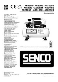
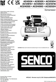
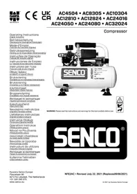
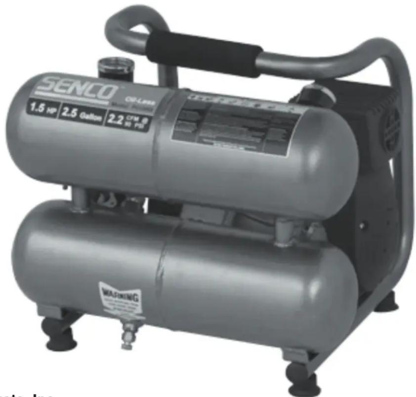
Exterior view of a Siemens air compressor unit (no signage or text in focus)Senco Products, Inc. 8485 Broadwell Rd. Cincinnati, OH 45244
Operating Instructions
© 2004 by Senco Products, Inc.
PC0968 Rev. 20-11-2013


Warnings for the safe use of this compressor are included in this manual.
Read and understand this manual.
TABLE OF CONTENTS
INTRODUCTION .... 3
SAFETY ALERT.... 3
INSPECTION 3
SAFETY WARNINGS .... 4
ELECTRICAL....4
EXPLOSION OR FIRE....5
BURSTING 5
BREATHING 6
BURNS 6
FLYING OBJECTS....6
MOVING PARTS....7
NEGLIGENCE 7
AIR COMPRESSOR DAMAGE 7
COMPRESSOR FEATURES 8
PREPARATION.... 10
INITIAL SET-UP 10
LOCATION.... 10
ELECTRICAL 10
OPERATION 11
PRE-START CHECKLIST 11
START-UP 11
SHUTDOWN 11
MAINTENANCE.... 11
TROUBLESHOOTING 12-14
SPECIFICATIONS 15
WARRANTY 16
INTRODUCTION
Congratulations on the purchase of your new SENCO® Air Compressor! You can be assured your SENCO Air Compressor was constructed with the highest level of precision and accuracy. Each component has been rigorously tested by technicians to ensure the quality, endurance and performance of this air compressor.
This operator's manual was compiled for your benefit. By reading and following the simple safety, installation and operation, and maintenance steps described in this manual, you will receive years of troublefree operation from your new SENCO Air Compressor. The contents of this manual are based on the latest product information available at the time of publication. The manufacturer reserves the right to make changes in price, color, materials equipment, specifications or models at any time without notice.

SAFETY ALERT!
A "DANGER, WARNING or CAUTION" safety warning will be surrounded by a "SAFETY ALERT BOX". This box is used to designate and emphasize Safety Warnings that must be followed when operating this air compressor. Accompanying the safety warnings are "Signal Words" which designate the degree or level of hazard seriousness. The "Signal Words" used in this manual are as follows:
DANGER: Indicates an imminently hazardous situation which, if not avoided. WILL result in death or serious injury.
WARNING: Indicates a potentially hazardous situation which, if not avoided, COULD result in death or serious injury.
CAUTION: Indicates a potentially hazardous situation which, if not avoided MAY result in minor or moderate injury or damage to the air compressor.
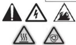
The symbols set to the left of this paragraph are "Safety Alert Symbols". These symbols are used to call attention to items or procedures that could be dangerous to you or other persons using this equipment.
ALWAYS PROVIDE A COPY OF THIS MANUAL TO ANYONE USING THIS EQUIPMENT. READ ALL INSTRUCTIONS IN THIS MANUAL AND ANY INSTRUCTIONS SUPPLIED BY MANUFACTURERS OF SUPPORTING EQUIPMENT BEFORE OPERATING THIS AIR COMPRESSOR AND ESPECIALLY POINT OUT THE "SAFETYWARNINGS" TO PREVENT THE POSSIBILITY OF PERSONAL INJURY TO THE OPERATOR.
INSPECTION
Unbox the air compressor and write in the serial number in the space provided below. Inspect for signs of obvious or concealed freight damage. Be sure that all damaged parts are replaced and any mechanical problems are corrected prior to the operation of the air compressor.
SERIAL NUMBER
If you have Questions e-mail: toolprof@Senco.com
Please have the following information available for all service calls:
- Model Number
- Serial Number
- Date and Place of Purchase
Senco, 8485 Broadwell Road, Cincinnati, OH 15244
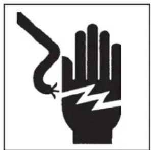
HAZARD
RISK OF ELECTRIC SHOCK OR ELECTROCUTION
natural_image
Black and white illustration of a hand with a lightning bolt symbol (no text or numbers)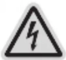
natural_image
Warning sign depicting a lightning bolt symbol (no text or numbers present)POTENTIAL CONSEQUENCE
Serious injury or death could occur if the air compressor is not properly grounded. Your air compressor is powered by electricity and may cause electric shock or electrocution if not used properly.
Electrical shock may occur from electrical cord.
Electrical shock may occur if air compressor is not operated properly.
Serious injury or death may occur if electrical repairs are attempted by unqualified persons
PREVENTION
Make sure the air compressor is plugged into a properly grounded outlet which provides correct voltage and adequate fuse protection.
Check power cord for signs of crushing, cutting or heat damage. Replace faulty cord before use
Keep all connections dry and off the ground. Do not allow electrical cords to lay in water or in such a positionwhere water could come in contact with them. Do not touch plug with wet hands.
Do not pull on the electrical cord to disconnect from the outlet.
Never operate air compressor in wet conditions or outdoors when it is raining.
Never operate air compressor with safety guards/covers removed or damaged.
Any electrical wiring or repairs performed on this air compressor should be done by Authorized Service Personnel in accordance with National and Local electrical codes.
Before opening any electrical enclosure, always shut off the air compressor, relieve pressure and unplug the air compressor from the power source. Allow air compressor to cool down. Never assume the air compressor is safe to work on just because it is not operating. It could restart at any time!
| HAZARC | POTENTIAL CONSEQUENCE | PREVENTION |
RISK OF EXPLOSION OR FIRE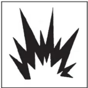  | Serious injury or death may occur from normal electrical sparks in motor and pressure switch.Serious injury may occur if any air compressor ventilation openings are restricted causing the air compressor to overheat and start on fire. | Always operate air compressor in a well ventilated area free of flammable vapors, combustible dust, gases or other combustible materials.If spraying flammable material, locate the air compressor at least 6 meters away from the spray area. (An additional hose may be required.)Never place objects against or on top of air compressor. Operate air compressor at least 30cm away from any wall or obstruction that would restrict proper ventilation. |
RISK OF BURSTINC | Serious injury or death may occur from an air tank explosion if air tanks are not properly maintained.Serious injury may occur from an air compressor malfunction or exploding accessories if incorrect system components, attachments or accessories are used. | Drain air tank daily or after each use to prevent moisture buildup in the air tankIf air tank develops a leak, replace the air tank immediately . Never repair, weld or make modifications to the air tank or its attachments.Never make adjustments to the factory set pressures.Never exceed manufacturers maximum allowable pressure rating of attachments.Because of extreme heat, do not use plastic pipe or lead tinsoldered joints for a discharge line.Never use air compressor to inflate small, low pressure objects such as toys.All hoses and fittings shall be suitable for site use at the maximum allowable working pressure of the portable compressor |
| HAZARE | POTENTIAL CONSEQUENCE | PREVENTION |
RISK TO BREATHING | Serious injury or death could occur from inhaling compressed air. The air stream may contain carbon monoxide toxic vapors or solid particles.Sprayed materials such as paint, paint solvents, paint remover, insecticides weed killers, etc. contain harmful vapors and poisons. | Never inhale air from the air compressor either directly or from a breathing device connected to the air compressor.Operate air compressor only in a well ventilated area. Follow all safety instructions provided with the materials you are spraying. Use of a respirator may be required when working with some materials. |
RISK OF BURNS | Serious injury could occur from touching exposed meta partsThese areas can remain hot for some time after the air compressor is shutdown. | Never allow any part of your body or other materials to make contact with any exposed metal parts on the air compressor, motor, or pipework. |
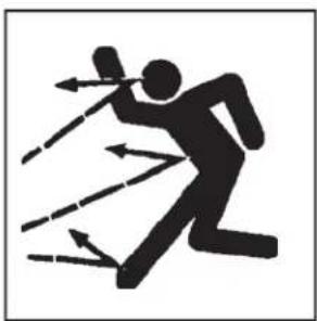
RISK OF FLYING OBJECTS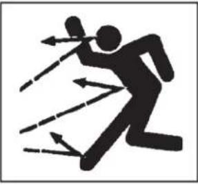 EYE PROTECTION MUST BE WORN EYE PROTECTION MUST BE WORN | Soft tissue damage can occur from the compressed air stream.Serious injury can occur from loose debris being propelled at a high speed from the compressed air stream. | Always wear OSHA required "Z87" safety glasses to shield the eyes from flying debris.Never point the airstream at any part of your body, anyone else or animalsNever leave pressurized air compressor unattended. Shut off air compressor and relieve pressure before attempting maintenance, attaching tools or accessories.Always maintain asafe distance from people and animals while operating the air compressor.Do not move the air compressor while air tank is under pressure. Do not attempt to move the air compressor by pulling on the hose. |
| HAZARC | POTENTIAL CONSEQUENCE | PREVENTION |
RISK FROM MOVING PARTS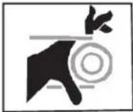 WARNING:UNIT MAY START WITHOUT WARNING WARNING:UNIT MAY START WITHOUT WARNING | Risk of bodily injury from moving partsThis air compressor cycles automatically when the pressure switch is in the “On/Auto” position.Risk of injury from negligent use. | Always turn off air compressor when not in use. Bleed pressure from the air hose and unplug from electrical outlet before performing maintenance. All repairs to the air compressor should be made by an Authorized Service person. Never assume the air compressor is safe to work on just because it is not operating. It could restart at any time!Do not operate without protective covers/guards. Replace damaged covers/guards before using the air compressor. |
RISK FROM NEGLIGENCE | Never allow children or adolescents to operate this air compressor!Stay alert-watch what you are doing.Do not operate the air compressor when fatigued or underthe influence of alcohol or drugs.Know how to stop the air compressor Be thoroughly familiar with controls. | |
| RISK OF AIR COMPRESSOR DAMAGE | Risk of major repair. | Do not operate air compressor without an air filter.Do not operate air compressor in a corrosive environmentAlways operate the air compressor in a stable, secure position to prevent air compressor from falling.Follow all maintenance instructions listec in this manual. |
! SAVE THESE INSTRUCTIONS!
COMPRESSOR FEATURES
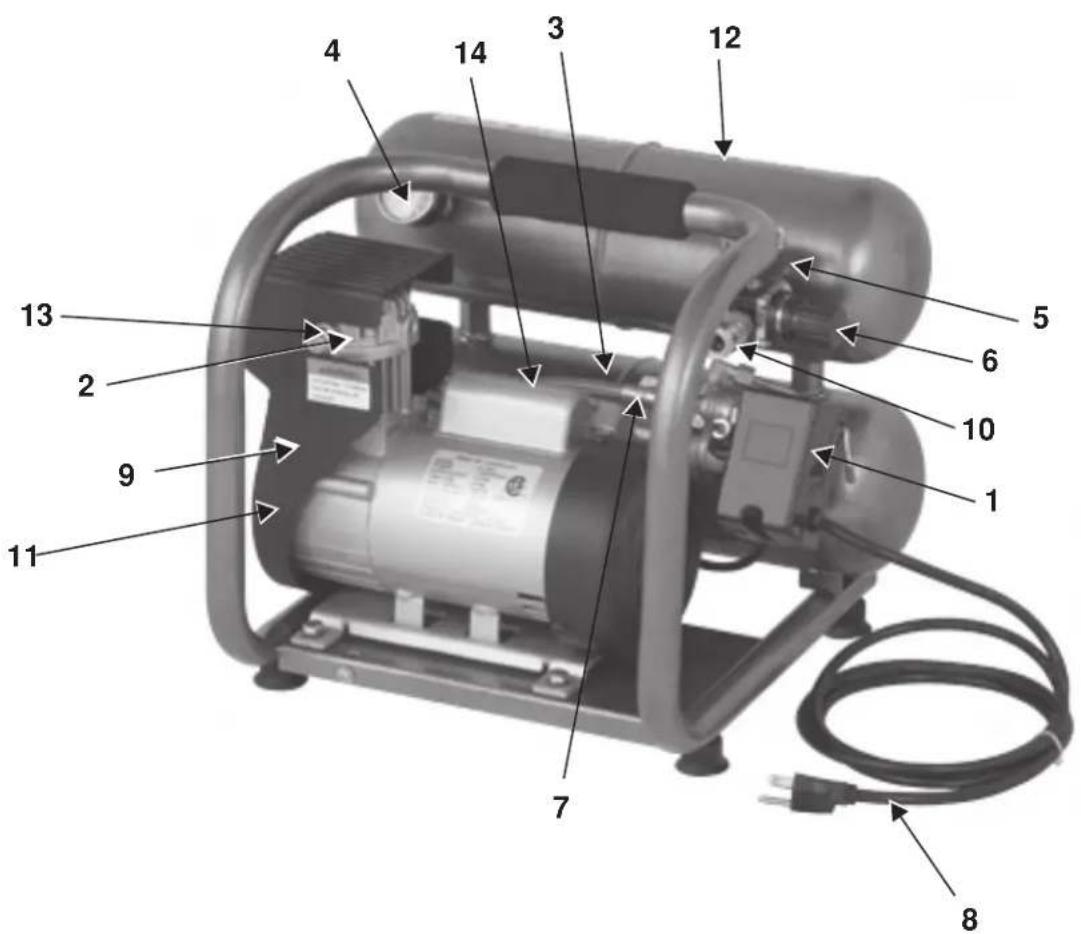
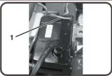
1 Motor/Pressure Switch
2 Air Compressor Pump
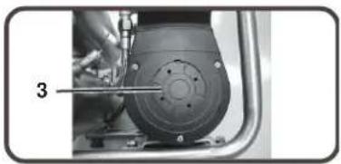
3 Safety Relief Valve
4 Tank Pressure Gauge
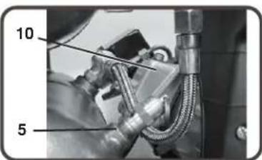
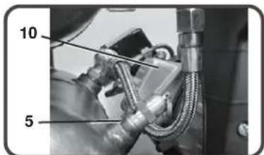
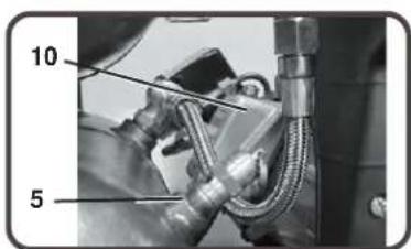
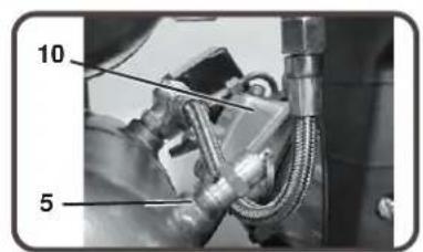
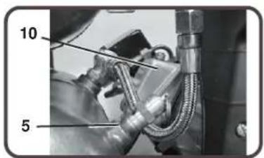
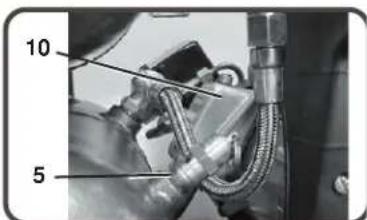
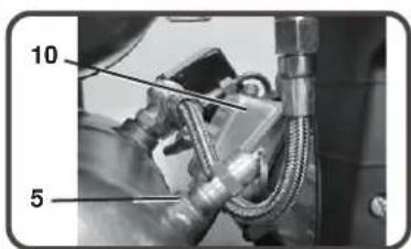
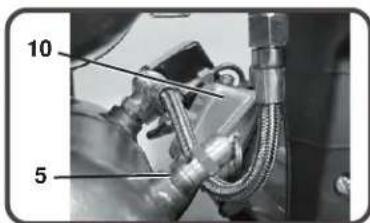
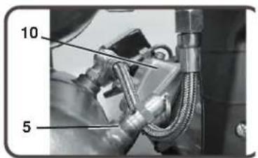
5 Outlet Pressure Gauge
6 Pressure Regulator
7 Discharge Line
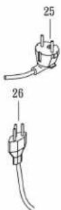
8 Electric Power Cord
9 Ventilation Openings/Protective Shroud
10 Quick Disconnect
11 Air Filter
12 Tank Drain
13 Cold Start Valve
14 Overload/Reset
COMPRESSOR FEATURES
1) MOTOR/PRESSURE SWITCH: This switch is used to start or stop the air compressor. Moving the switch to the On (1) position will provide automatic power to the pressure switch which will allow the motor to start when the air tank pressure is below the factory set cut-in pressure. When in the O n (1), the pressure switch stops the motor when the air tank pressure reaches the factor set cut-out pressure. For safety purposes, this switch also has a pressure release valve located on the side of the switch designed to automatically release compressed air from the air compressor pump head and its discharge line when the air compressor reaches cut-out pressure or is shut off. This allows the motor to restart freely. Moving the switch to the Off (0) position will remove power from the pressure switch and stop the air compressor.
2) MOTOR THERMAL OVERLOAD: The electric motor has a thermal overload protector. If the motor overheats for any reason, the thermal overload will cut off power, thus preventing the motor from being damaged. Wait until the motor is cool. Motor also has a magnetic breaker. Reset switch if it is tripped.
3) AIR INTAKE FILTER: This filter is designed to clean air coming into the pump. To ensure the pump continually receives a clean, cool, dry air supply this filter must always be clean and ventilation opening free from obstructions. The filter can be removed for cleaning by using warm, soapy water. Rinse the filter and air dry.
4) AIR COMPRESSOR PUMP: To compress air, the piston moves up and down in the cylinder. On the downstroke, air is drawn in through the air intake valve while the exhaust valve remains closed. On the upstroke, air is compressed, the intake valve closes and compressed air is forced out through the exhaust valve, into the discharge line, through the check valve and into the air tank.
5) SAFETY RELIEF VALVE: This valve is designed to prevent system failures by relieving pressure from the system when the compressed air reaches a predetermined level. The valve is preset by the manufacturer and must not be modified in any way. To verify the valve is working properly, pull on the ring. Air pressure should escape. When the ring is released, it will reseat.
6) AIR TANK DRAIN VALVE: The drain valve is used to remove moisture from the air tank(s) after the air compressor is shut off. NEVER attempt to open the drain valve when more than 0.7 bar of air pressure is in the air tank! To open the drain valve, turn the knob counterclockwise. Tilt tank to ensure that all condensation drains through valve.
7) AIR TANK PRESSURE GAUGE: The air tank pressure gauge indicates the reserve air pressure in the air tank (s).
8) OUTLET PRESSURE GAUGE: The outlet pressure gauge indicates the air pressure available at the outlet side of the regulator. This pressure is controlled by the regulator and is always less or equal to the air tank pressure.
9) PRESS URE REGULATOR: The air pressure coming from the air tank is controlled by the regulator knob. Turnthe pressure regulation knob clockwise to increase discharge pressure, and counterclockwise to decrease discharge pressure.
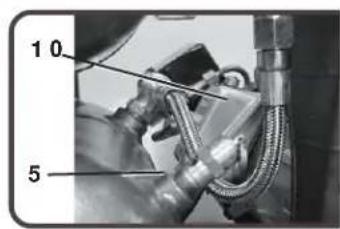
10) DISCHARGE LINE: Please note that the discharge line is very hot.
HOT SURFACES: Do not remove protective shroud. High temperature after sustained use.
natural_image
Close-up of a mechanical component with labeled part '1' and cable, no readable text or symbols beyond label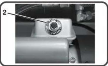
natural_image
Close-up of a mechanical component with a knob and attached tubing (no visible text or symbols)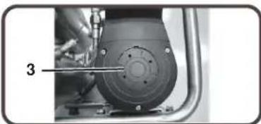
natural_image
Close-up of a mechanical component with a tool inserted, showing a circular component and bolt holes (no text or symbols visible)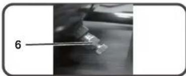
natural_image
Close-up of a small electronic component being held by tweezers, labeled with number 6 (no text or symbols on the object itself)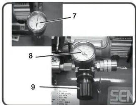
PREPARATION
INITIAL SET-UP:
- Read safety warnings before setting-up air compressor.
LOCATION:
CAUTION
In order to avoid damaging the air compressor, do not incline the air compressor transversely or longitudinally more than 10^ .
- Place air compressor at least 30cm away from obstacles that may prevent proper ventilation.
Do not place air compressor in an area:
-where there is evidence of oil or gas leaks.
-where flammable gas vapors or materials may be present.

WARNING
Serious injury or death may occur if electricalsparks from motor and pressure switch come in contact with flammable vapors, combustible dust, gases or other combustible materials. When using the air compressor for spray painting, placethe air compressor as far away I from the work area as possible, using extra air hoses instead of extension cords.
-where air temperatures fall below 0°C or exceed 40°C.
-where extremely dirty air or water could be drawn into the air compressor.
ELECTRICAL:

DANGER
Improper connection of the equipment-grounding conductor can result in a risk of shock or electrocution. Check with a qualified electrician or service personnel in doubt as to whether the outlet is properly grounded. Do not use any type of with this product. If repair or replacement of the cord or plug is necessary, do not use the grounding wire to either flat blade terminal. The wire with insulation having surface that is green with or without yellow stripes is the grounding wire.

WARNING
This product must be grounded. If there should be a malfunction or breakdown, grounding provides a path of least resistance for electric current to reduce the risk of electric shock. This product is equipped with a cord having an equipmentgrounding conductor and a grounding type plug. The plug must be plugged into an appropriate outlet that is properly installed and grounded in accordance with all local codes and ordinances.
- SENCO® DOES NOT RECOMMEND THE USE OF EXTENSION CORDS as this can create power loss and overheating of the motor. Use of an additional air hose is recommended rather than an extension cord. If use of an extension cord is unavoidable, it should be plugged into a GFCI found in circuit boxes or protected receptacles. When using an extension cord, observe the following:
| Cable Length | Wire | Gauge |
| Up to 8 meters | 12 | AWG |
| Up to 30 meters | 10 | AWG |
| Up to 50 meters | 8 | AWG |
| Up to 75 meters | 6 | AWG |
Use only 3-blade extension cords that have 3-blade grounding-type plugs and 3-slot cord connectors that will accept the plug from the product. Use only extension cords having an electrical rating not less than the rating of the product. Do not use damaged extension cords. Examine extension cord before using and replace it damaged. Do not abuse extension cord and do not yank on any cord to disconnect. Keep cord away from heat and sharp edges. Always shut off the air compressor switch before removing the plug from the receptacle.
OPERATION
PRE-START CHECKLIST:
- Remove any moisture in the air compressor air tank. Remove excessive pressure with an air tool, then open the air tank drain valve in the bottom of the air tank. Close tightly when drained.

- Make sure the air compressor Motor Switch is in the "OFF" (0) position.
- Make sure all safety valves are working correctly.
- Make sure all guards and covers are in place and securely mounted.
START-UP:
- Ensure the lever on the pressure switch box is in the "OFF" (0)position.
- Plug the power cord into a grounded outlet.
- Move the lever on the pressure switch box to the On (1) position.
- AUTO OPERATION: The ON position will allow the air compressor to "START" building up pressure in the air tanks and "STOP" when correct pressure is achieved. When pressure drops with usage, the air compressor will "START" building up pressure again.
- Set pressure by adjusting the pressure regulator knob counterclockwise for less pressure and clockwise for more pressure.
- If you notice any unusual noise or vibration, stop the air compressor and refer to "Troubleshooting".
SHUTDOWN:
- To stop the air compressor, move the lever on the pressure switch box to the "OFF" (0) position. NEVER stop the air compressor by unplugging it from the power source. This could result in risk of electrocution.
- Drain air from the air tank by releasing air with an attached air tool or by pulling on the safety relief valve ring.
- Once pressure in the air tanks register under 0.7 bar, open the drain valve undereach air tank to drain any moisture.
- Allow the air compressor to cool down.
- Wipe air compressor clean and store in a safe, non-freezing area.
MAINTENANCE
Head the instruction manual before performing maintenance. The following procedures must be performed when stopping the air compressor for maintenance or service.
- Turn off air compressor.
WARNING: Never assume the air compressor is safe to work on just because it is not operating. It could restart at any time!
- Disconnect cord from mainpower supply.
- Open all drains.
- Wait for the air compressor to cool before starting service.
MAINTENANCE CHART
| PROCEDURE | DAILY | WEEKLY | MONTHLY |
| Drain condensation in air tank(s) | X | ||
| Check for unusual noise/vibration | X | ||
| Check for air leaks | X | ||
| Inspect air filter | X | ||
| Clean exterior of compressor | X | ||
| Check safety relief valve | X |
TROUBLESHOOTING
Symptom 1. Motor will not run or restart.
| Power cord not plugged n. | Plug cord into grounded outlet. |
| Motor/Pressureswitch in “OFF” (0) position. | Move switch to “ON” (1) position. |
| Motor thermal overload switch has tripped. | Turn air compressor off, wait until motor is cool, then check motor circuit breaker. |
| Fuse blown or circuit breaker has tripped. | Replace fuse or reset circuit breaker. |
| Check for proper fuse amperage. | |
| Check for low voltage conditions. | |
| Disconnect any other electrical appliances from circuit or operate air compressor on its own branch circuit. | |
| Wrong gauge wire or length of extensor cord | Check chart on page #10 for proper gauge wire and cord length. |
| Air tank pressure exceeds motor/pressure switch “cut-in” pressure. | Motor will start automatically when air tank pressure drops below “cut-in” pressure of motor/pressure switch. |
| Pressure release valve on motor/pressure switch has not unloaded pump head pressure. | Bleed the line by moving the switch to the “Off” (0) position. |
| Detective motor, motor capacitor, motor/pressure switch, or check valve. | Contact Senco Customer Service. |
Symptom 2. When in the Start/Stop option, motor runs continuously.
| PROBABLE CAUSEMotor/Pressure switch does not shut off motor when air compressor reaches “cut-out” pressure and safety relief valve activates. | REMEDYMove the motor/pressure switch to the “Off”(0) positionIf the motor doesn’t shutoff, unplug the air compressor.If the electrical contacts are welded together, replace the pressure switch. |
| Air compressor is incorrectly sized. | Limit the air pressure to the capacity of the air compressor. Either use a smaller tool or a larger air compressor. |
Symptom 3. Air continues to leak at motor/pressure switch release valve after motor stops.
| PROBABLE CAUSE | REMEDY |
| The check valve is stuck open. | Remove, clean or replace. |
TROUBLESHOOTING
Symptom 4. Air continues to leak at motor/pressure switch release valve while motor is running.
| PROBABLE CAUSE | REMEDY |
| Defective motor/pressure switch. | Replace. |
Symptom 5. Air leaks from safety relief valve.
| PROBABLECAUSEPossible defective safety relief valve. | REMEDYOperate safety relief valve manually by pulling on ring.If it still leaks, it should be replaced. |
| Excessive air tank pressure. | Defective motor/pressure switch. Replace. |
Symptom 6. Air leaks at fittings.
| PROBABLE CAUSEFittings are not tight enough. | REMEDYTighten ittings where air can be heard escaping. Check fittings with soapy water solution. Do not overtighten. |
Symptom 7. Air leak in air tank.
| PROBABLE CAUSEDefective or rusted air tank. | REMEDYAir tank must be replaced.Do not attempt to repair air tank! Do not weld, repair or make modifications. |
Symptom 8. Air blowing from inlet filter.
| PROBABLE CAUSE | REMEDY |
| Damaged inlet (reed) valve. | Contact SENCO Customer Service |
Symptom 9. Insufficient pressure at air tool or accessory.
| PROBABLE CAUSEPressure regulator knob not turned to high enough pressure or defective pressure regulator. | REMEDYAdjust pressure regulator knob to proper setting or replace. |
| Restricted air intake filter. | Clean. |
| Air leaks. | Check for leaks and repair. |
| Air compressor is not large enough for air requirement. | Check the accessory air requirement. If it is higher than the CFM or pressure supply of the air compressor, you need a larger air compressor. |
TROUBLESHOOTING
Symptom 10. Air compressor not making enough air.
PROBABLE CAUSE
Restricted air intake filter.
Defective (reed) valve.
REMEDY
Clean.
Drain air tank and measure pump up time. Compare to specifications. If lower, remove pump head and inspect valve plate, clean or replace.
Symptom 11. Moisture in discharge air.
PROBABLE CAUSE
Condensation in air tank caused by high level of atmospheric humidity or air compressor is not run long enough.
REMEDY
Drain air tank after every use. Drain air tank more often in humid weather and use an air line filter.
MODEL : PC0968 EU
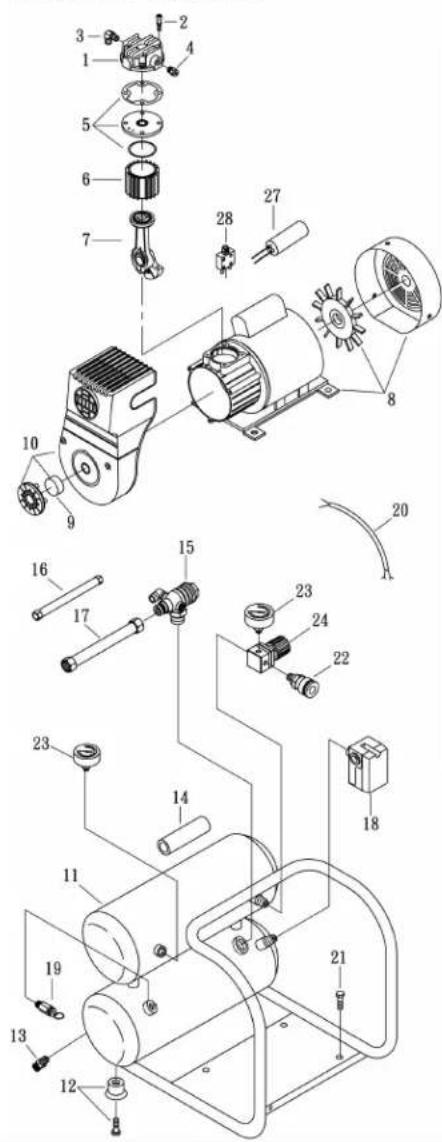
SPARE PARTS LIST
NO : RLB-1311
| REF. NO. | DESCRIPTION | PART NO. | QTY. |
| 1 | Cylinder head | 3101096H | 1 |
| 2 | Allen bolt set | 3B01-M06*080V | 4 |
| 3 | Exhaust elbow | 2N06-02T03HL | 1 |
| 4 | Auto relief valve | 2409003 | 1 |
| 5 | Exhaust valve seat set | 3B11-A9000A | 1 |
| 6 | Cylinder | 3201065 | 1 |
| 7 | Piston rod set | 3B34-MB57 | 1 |
| 8 | Motor set | 3B8-MB5706S | 1 |
| 9 | Filter element | 2142014 | 1 |
| 10 | Shroud | 2428012RS | 1 |
| 11 | Air tank | 3401497QJ | 1 |
| 12 | Rubber pad set | 3433011-ARS | 4 |
| 13 | Drain valve | 2405012 | 1 |
| 14 | Grip | 2432102RS | 1 |
| 15 | Check valve set | 2414036RX | 1 |
| 16 | Unloading tube | 3B2-02*190F | 1 |
| 17 | Exhaust tube | 2T02-03*0260RS | 1 |
| 18 | Pressure switch | 2E21-DA256APS | 1 |
| 19 | Pressure relief valve | 2406021A | 1 |
| 20 | Cable | 2E02-1C30382Y2T | 1 |
| 21 | Hexagon bolt | 3B00-FM08*015RSV | 4 |
| 22 | Quick coupler | 07S1/4M-ERS | 1 |
| 23 | Pressure gauge | 2D12-15D14BAR | 2 |
| 24 | Regulator | 2408008LRS | 1 |
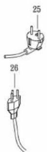
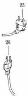
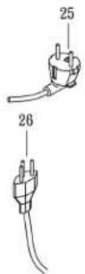
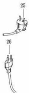
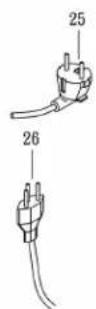
| 25 | Power cable(2pin) | 2E01-029S | 1 |
| 26 | Power cable(3pin) | 2E01-044S | 1 |
| 27 | Running capacitor | 2E27-010F4535 | 1 |
| 28 | Breaker | 2E25-03A | 1 |
SPECIFICATIONS
| Model # | PC0968 EU |
| Motor | |
| Horsepower | 0.54 KW |
| Voltage | 230 |
| Amperage | 6 |
| Hz. | 50 |
| Phase | Single |
| RPM | 2850 |
| Compressor Pump | |
| Number of Cylinders | 1 |
| Compression Stage | 1 |
| Crankcase | Aluminum |
| Bearings | Ball |
| Cylinder | Aluminum |
| Valves | Reed-Single |
| Head | Aluminum |
| Filter | Insert |
| Motor/Pressure SwitchSetting | |
| Cut-out | 125 PSI (8.6 bar) |
| Cut-in | 90 PSI (6.2 bar) |
| Controls | ON (1) / OFF (0) |
| Air tank | |
| CapacityCapacity | 2.5 gallon (10 liter) |
| Performance | |
| CFM Air Displacement | 4 |
| CFM @ 2.8 bar | 1.8 |
| CFM @ 6.2 bar | 1.4 |
| Maximum Pressure | 8.6 bar |
| Pump-up Time: 0-8.3 bar | 85 sec. |
| Recovery Recovery | 17 seconds |
| Weighteight | |
| Net 17.3 kg17.3 kg | |
| Dimensions | |
| Basic LxWxH | 40cmx38cmx34cm |
| Measured sound power level [dB] | 79 dBA |
| Guaranteed sound power level [dB] | 81 dBA |
SENCO COMPRESSOR AND PARTS WARRANTY
Model PC0968
This compressor has been designed and constructed using the highest standards of material and workmanship.
COMPRESSOR WARRANTY:
The length of this guarantee is 1 year from date of purchase by the original retail purchaser. During this period, Senco Products, Inc., will repair or replace at Senco's option, any original part or parts for the original retail purchaser. This will be done free of charge, provided the parts are determined defective in materials or workmanship upon examination by a Senco Authorized Warranty Service Center, with the exceptions and exclusions described below. Any replacement part provided will carry a warranty for the balance of the period of warranty applicable to the part t replaces. When repair or replacement of bats or compressor is necessary, the original retail purchaser returns the complete compressor or part, with transportation prepaid, to the nearest Senco Authorized Warranty Service Center, with purchase receptor other positive proof that the part or compressor is within the warranty period.
EXCLUSIONS:
- This warranty does not cover parts damaged due to normal wear, misapplication, misuse, accidents, operation at other than recommended speeds or voltage (electric units only), improper storage, or damages resulting during shipping.
- Deviation from operating instructions, specifications, and maintenance schedules.
- Labor charges, oss or damageresulting from improper operation, maintenance or repairs made by person(s) other than a Senco Authorized Warranty Service Center.
- The use of other thangenuine Senco RepairParts will void warranty.
This warranty is contingent upon proper use of the compressor by purchaser and does not cover:
A) Abnormal conditions, accident, neglect, misuse or improper storage of the unit.
B) Deviation from operating or maintenance nstructions.
C) Modifications not authorized by Senco.
D) Repairs or maintenance (other than routine air tank draining required by your operating and maintenance manual) made by persons other than Senco or its authorized agents.
E) Freight damage.
THIS WARRANTY IS THE ONLY WARRANTY ON THIS COMPRESSOR, AND ALL OTHER WARRANTIES, WHETHER ORAL, WRITTEN, EXPRESS, OR IMPLIED, INCLUDING, BUT NOT LIMITED TO, THE IMPLIED WARRANTY OF MERCHANTABILITY OR FITNESS FOR A PARTICULAR PURPOSE, ARE EXCLUDED. BUYER'S OR USER'S REMEDIES ARE SOLELY AND EXCLUSIVELY AS STATED ABOVE. SENCO PRODUCTS, INC. SHALL IN NO EVENT BE LIABLE FOR INCIDENTAL, CONSEQUENTIAL, INDIRECT, OR SPECIAL DAMAGES. IN NO EVENT, WHETHER AS A RESULT OF A BREACH OF CONTRACT, WARRANTY, TORT INCLUDING NEGLIGENCE) OR OTHERWISE, SHALL SENCO'S LIABILITY EXCEED THE PRICE OF THE COMPRESSOR WHICH HAS GIVEN RISE TO THE CLAIM OR LIABILITY. ANY LIABILITY CONNECTED WITH THE USE OF THIS COMPRESSOR SHALL TERMINATE JPON THE EXPIRATION OF THE WARRANTY PERIOD SPECIFIED ABOVE.
Replacement of Compressor Due to Natural Disaster
Senco will also replace any compressor destroyed by an Act of God such as flood, earthquake, hurricane or other disaster resulting only from the forces of nature. Such a claim will be honored provided that such original retail purchaser had previously submitted a completed warranty registration card, and then submits proof of ownership and an acceptable statement describing such Act of God documented by an insurance carrier, police department, or other official governmental source.
SENCO PRODUCTS, INC.
CINCINNATI, OHIO 45244-1611 USA
natural_image
Exterior view of a Siemens CIO-Large air compressor unit (no signage or text on body)Senco Products, Inc.
8485 Broadwell Rd.
Cincinnati, OH 45244
Bedienungsanleitung
© 2004 by Senco Products, Inc.
PC0968 Rev. 20-11-2013

GEFAHR DURCH EINATMEN....6
GEFAHR VON VERBRENNUNGEN....6
natural_image
Close-up of a mechanical component with labeled part '1' (no readable text or symbols beyond label)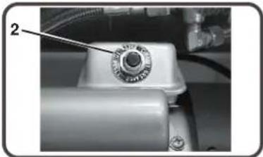
natural_image
Close-up of a mechanical component with a dial and attached tubing (no visible text or symbols)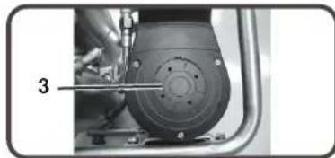
natural_image
Close-up of a mechanical component with a tool inserted, showing a circular component and a numbered label '3' (no readable text or symbols)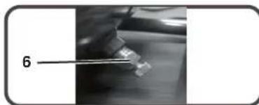
natural_image
Close-up of a hand holding a small object with a label '6' pointing to it (no other text or symbols visible)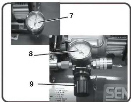
VORBEREITUNG
SPARE PARTS LIST
NO : RLB-1311
| REF. NO. | DESCRIPTION | PART NO. | QTY. |
| 1 | Cylinder head | 3101096H | 1 |
| 2 | Allen bolt set | 3B01-M06*080V | 4 |
| 3 | Exhaust elbow | 2N06-02T03HL | 1 |
| 4 | Auto relief valve | 2409003 | 1 |
| 5 | Exhaust valve seat set | 3B11-A9000A | 1 |
| 6 | Cylinder | 3201065 | 1 |
| 7 | Piston rod set | 3B34-MB57 | 1 |
| 8 | Motor set | 3B8-MB5706S | 1 |
| 9 | Filter element | 2142014 | 1 |
| 10 | Shroud | 2428012RS | 1 |
| 11 | Air tank | 3401497QJ | 1 |
| 12 | Rubber pad set | 3433011-ARS | 4 |
| 13 | Drain valve | 2405012 | 1 |
| 14 | Grip | 2432102RS | 1 |
| 15 | Check valve set | 2414036RX | 1 |
| 16 | Unloading tube | 3B2-02*190F | 1 |
| 17 | Exhaust tube | 2T02-03*0260RS | 1 |
| 18 | Pressure switch | 2E21-DA256APS | 1 |
| 19 | Pressure relief valve | 2406021A | 1 |
| 20 | Cable | 2E02-1C30382Y2T | 1 |
| 21 | Hexagon bolt | 3B00-FM08*015RSV | 4 |
| 22 | Quick coupler | 07S1/4M-ERS | 1 |
| 23 | Pressure gauge | 2D12-15D14BAR | 2 |
| 24 | Regulator | 2408008LRS | 1 |
| 25 | Power cable(2pin) | 2E01-029S | 1 |
| 26 | Power cable(3pin) | 2E01-044S | 1 |
| 27 | Running capacitor | 2E27-010F4535 | 1 |
| 28 | Breaker | 2E25-03A | 1 |
TECHNISCHE DATEN
natural_image
Exterior view of a Siemens Air Conditioner (CIS-Laser) with two cylindrical units and attached pipes (no visible text or symbols on the device body)Senco Products, Inc.
8485 Broadwell Rd.
Cincinnati, OH 45244
Gebruiksaanwijzing
© 2004 by Senco Products, Inc.
PC0968 Rev. 20-11-2013
INHOUDSOPGAVE
INLEIDING.... 3
VEILIGHEIDSATTENTIE....3
INSPECTIE....3
VEILIGHEIDSWAARSCHUWINGEN.... 4
ELEKTRICITEIT....4
EXPLOSIE OF VUUR....5
BARSTEN....5
INADEMEN....6
BRANDWONDEN....6
VLIEGENDE VOORWERPEN 6
BEWEGENDE ONDERDELEN....7
NALATIGHEID....7
SCHADE AAN LUCHTCOMPRESSOR....7
COMPRESSORKENMERKEN....8
VOORBEREIDING....10
EERSTE INSTELLING....10
LOCATIE....10
ELEKTRICITEIT....10
BEDIENING....11
CONTROLELIJST VÓÓR START....11
OPSTARTEN....11
UITSCHAKELEN....11
ONDERHOUD....11
PROBLEMEN OPLOSSEN.... 12-14
SPECIFICATIES....15
GARANTIE....16
INLEIDING
VEILIGHEIDSWAARSCHUWINGEN
LEES ALLE VEILIGHEIDSWAARSCHUWINGEN VOORDAT
DE LUCHTCOMPRESSOR WORDT GEBRUIKT
GEVAAR
VEILIGHEIDSWAARSCHUWINGEN
I EFS AI I F VEII IGHEIDSWAARSCHUWINGFN VOORDAT
DE LUCHTCOMPRESSOR WORDT GEBRUIKT
natural_image
Close-up of a mechanical component with labeled part '1' (no readable text or symbols beyond label)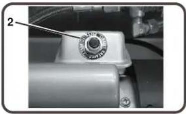
natural_image
Close-up of a mechanical component with a dial and labeled part (no readable text or symbols)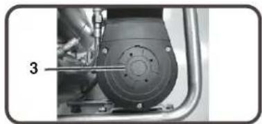
natural_image
Close-up of a mechanical component with a tool inserted, no visible text or symbols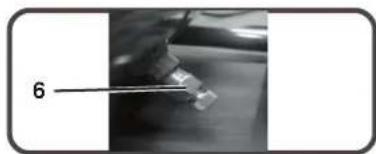
natural_image
Close-up of a small electronic component being held by tweezers, labeled with number 6 (no text or symbols on the object itself)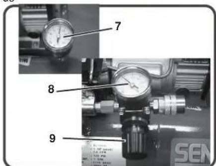
VOORBEREIDING
EERSTE INSTELLING:
SPARE PARTS LIST
NO : RLB-1311
| REF. NO. | DESCRIPTION | PART NO. | QTY. |
| 1 | Cylinder head | 3101096H | 1 |
| 2 | Allen bolt set | 3B01-M06*080V | 4 |
| 3 | Exhaust elbow | 2N06-02T03HL | 1 |
| 4 | Auto relief valve | 2409003 | 1 |
| 5 | Exhaust valve seat set | 3B11-A9000A | 1 |
| 6 | Cylinder | 3201065 | 1 |
| 7 | Piston rod set | 3B34-MB57 | 1 |
| 8 | Motor set | 3B8-MB5706S | 1 |
| 9 | Filter element | 2142014 | 1 |
| 10 | Shroud | 2428012RS | 1 |
| 11 | Air tank | 3401497QJ | 1 |
| 12 | Rubber pad set | 3433011-ARS | 4 |
| 13 | Drain valve | 2405012 | 1 |
| 14 | Grip | 2432102RS | 1 |
| 15 | Check valve set | 2414036RX | 1 |
| 16 | Unloading tube | 3B2-02*190F | 1 |
| 17 | Exhaust tube | 2T02-03*0260RS | 1 |
| 18 | Pressure switch | 2E21-DA256APS | 1 |
| 19 | Pressure relief valve | 2406021A | 1 |
| 20 | Cable | 2E02-1C30382Y2T | 1 |
| 21 | Hexagon bolt | 3B00-FM08*015RSV | 4 |
| 22 | Quick coupler | 07S1/4M-ERS | 1 |
| 23 | Pressure gauge | 2D12-15D14BAR | 2 |
| 24 | Regulator | 2408008LRS | 1 |
| 25 | Power cable(2pin) | 2E01-029S | 1 |
| 26 | Power cable(3pin) | 2E01-044S | 1 |
| 27 | Running capacitor | 2E27-010F4535 | 1 |
| 28 | Breaker | 2E25-03A | 1 |
SPECIFICATIES
| Modelnr. | PC0968 EU | |
| Motor | ||
| Vermogen (pk)SpanningStroomsterkte 6FasetPM | 0.54 KW230Hz. 50Enkelvoudig2850 | |
| Compressorpomp | Aantal cilindersCompressiefaseCarterLagersCilinderKleppenKopFilter | 11AluminumKogelAluminumEnkelvoudige reedklepAluminumInvoegen |
| Instellingmotor/drukschakelaar | UitschakeldrukInschakeldruk | 8.6 bar6.2 bar |
| Bedieningselementen | Start/stop | |
| Luchttank | Inhoud | 10 liter |
| Prestaties | LuchtverplaatsingCFM @ 2.8 barCFM @ 6.2 barMaximumdrukPomptijd: 0 - 0,83 MPaHersteltijd: | 8.61.81.48.6 bar85 sec.(6.2-8.3 bar) 17seconden |
| Gewicht: | Netto | 17.3 kg |
| Afmetingen: | Basis LxBxH | 40x38x34 cm |
| FBTVSFE:TPVOE:QPXFS:WFWF:E#> | dBA | |
( VBSBOUFFE ]TPVOE ]QPX FS ]MFWFM
GARANTIE VOOR SENCO-COMPRESSOR EN ONDERDELEN
Model PC0968
CINCINNATI, OHIO 45244-1611 VS
natural_image
Exterior view of a Siemens Air Conditioner (CIS-LAX) air compressor unit with two cylindrical tanks and control panel (no visible text or symbols on the device itself)Senco Products, Inc.
8485 Broadwell Rd.
Cincinnati, OH 45244
© 2004 by Senco Products, Inc.
PC0968 Rev. 20-11-2013

PIÈCES EN MOUVEMENT 7
NÉGLIGENCE 7
DOMMAGES AU COMPRESSEUR 7
CARACTÉRISTIQUES DU COMPRESSEUR 8
PRÉPARATION....10
MISE EN ŒUVRE INITIALE 10
EMPLACEMENT 10
ALIMENTATION ÉLECTRIQUE ....10
FONCTIONNEMENT 11
LISTE DE VÉRIFICATIONS PRÉLIMINAIRES . .....11
DÉMARRAGE 11
COUPURE 11
ENTRETIEN 11
DÉPANNAGE 12-14
SPÉCIFICATIONS 15
GARANTIE 16
INTRODUCTION
natural_image
Abstract black-and-white graphic of a stylized human figure with cloud-like patterns on the back (no text or symbols)CONSÉQUENCES POTENTIELLES
natural_image
Silhouette of a person in motion with arrows indicating movement direction (no text or symbols)natural_image
Simple icon of a person wearing glasses inside a circle (no text or symbols)natural_image
Close-up of a mechanical component with wires and a labeled part (no readable text or symbols)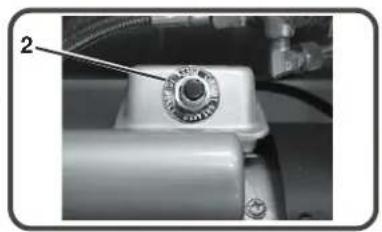
natural_image
Close-up of a mechanical component with a circular knob and labeled part (no readable text or symbols)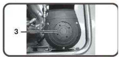
natural_image
Close-up of a mechanical component with a tool inserted, showing a circular component and a numbered label '3' (no readable text or symbols)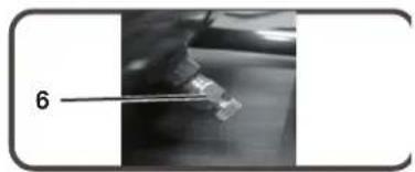
natural_image
Close-up of a hand holding a small object with a label '6' pointing to it, against a blurred background (no readable text or symbols)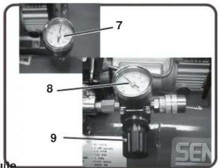
PRÉPARATION
MISE EN ŒUVRE INITIALE :
SPARE PARTS LIST
NO:RLB-1311
| REF. NO. | DESCRIPTION | PART NO. | QTY. |
| 1 | Cylinder head | 3101096H | 1 |
| 2 | Allen bolt set | 3B01-M06*080V | 4 |
| 3 | Exhaust elbow | 2N06-02T03HL | 1 |
| 4 | Auto relief valve | 2409003 | 1 |
| 5 | Exhaust valve seat set | 3B11-A9000A | 1 |
| 6 | Cylinder | 3201065 | 1 |
| 7 | Piston rod set | 3B34-MB57 | 1 |
| 8 | Motor set | 3B8-MB5706S | 1 |
| 9 | Filter element | 2142014 | 1 |
| 10 | Shroud | 2428012RS | 1 |
| 11 | Air tank | 3401497QJ | 1 |
| 12 | Rubber pad set | 3433011-ARS | 4 |
| 13 | Drain valve | 2405012 | 1 |
| 14 | Grip | 2432102RS | 1 |
| 15 | Check valve set | 2414036RX | 1 |
| 16 | Unloading tube | 3B2-02*190F | 1 |
| 17 | Exhaust tube | 2T02-03*0260RS | 1 |
| 18 | Pressure switch | 2E21-DA256APS | 1 |
| 19 | Pressure relief valve | 2406021A | 1 |
| 20 | Cable | 2E02-1C30382Y2T | 1 |
| 21 | Hexagon bolt | 3B00-FM08*015RSV | 4 |
| 22 | Quick coupler | 07S1/4M-ERS | 1 |
| 23 | Pressure gauge | 2D12-15D14BAR | 2 |
| 24 | Regulator | 2408008LRS | 1 |
| 25 | Power cable(2pin) | 2E01-029S | 1 |
| 26 | Power cable(3pin) | 2E01-044S | 1 |
| 27 | Running capacitor | 2E27-010F4535 | 1 |
| 28 | Breaker | 2E25-03A | 1 |

SPÉCIFICATIONS
Guaranteed sound power level [dB] 81 dBA
GARANTIE SENCO POUR LE COMPRESSEUR ET LES PIÈCES
Model PC0968
natural_image
Exterior view of a Siemens Air Conditioner (CIO-LAX) industrial air compressor unit with two cylindrical tanks and control panel (no visible text or symbols on the device itself)Senco Products, Inc.
8485 Broadwell Rd.
Cincinnati, OH 45244
Käyttöohje
© 2004 by Senco Products, Inc.
PC0968 Rev. 20-11-2013

RÄJÄHDYS TAI TULIPALO....5
RÄJÄHDYS....5
HENGITTÄMINEN 6
PALOVAMMAT 6
LENTÄVÄT ESINEET....6
LIIKKUVAT OSAT....7
HUOLIMATTOMUUS 7
PAINEILMAKOMPRESSORIN VAURIOITUMINEN...... 7
KOMPRESSORIN OMINAISUUDET.... 8
ALKUVALMISTELUT....10
ENSIMMÄINEN KÄYTTÖÖNOTTO....10
SIJOITTAMINEN....10
SÄHKÖ....10
KÄYTTÖ....11
TEHTÄVÄ ENNEN KÄYNNISTYSTÄ 11
KÄYNNISTYS.... 11
SAMMUTUS.... 11
HUOLTO 11
VIANETSINTÄ....12-14
TEKNISET TIEDOT....15
TAKUU....16
JOHDANTO
natural_image
Close-up of a mechanical component with labeled part '1' (no readable text or symbols beyond label)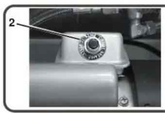
natural_image
Close-up of a mechanical component with a circular knob and metallic parts (no visible text or symbols)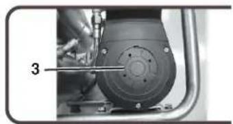
natural_image
Close-up of a mechanical component with a numbered annotation (3) pointing to a tool, no visible text or symbols on the main subject.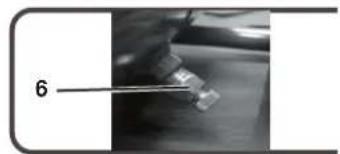
natural_image
Close-up of a precision tool interacting with a small object, labeled with number 6 (no text or symbols on the object itself)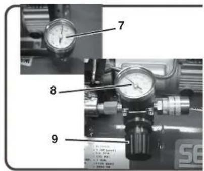
ALKUVALMISTELUT
ENSIMMÄINEN KÄYTTÖÖNOTTO:
SPARE PARTS LIST
NO : RLB-1311
| REF. NO. | DESCRIPTION | PART NO. | QTY. |
| 1 | Cylinder head | 3101096H | 1 |
| 2 | Allen bolt set | 3B01-M06*080V | 4 |
| 3 | Exhaust elbow | 2N06-02T03HL | 1 |
| 4 | Auto relief valve | 2409003 | 1 |
| 5 | Exhaust valve seat set | 3B11-A9000A | 1 |
| 6 | Cylinder | 3201065 | 1 |
| 7 | Piston rod set | 3B34-MB57 | 1 |
| 8 | Motor set | 3B8-MB5706S | 1 |
| 9 | Filter element | 2142014 | 1 |
| 10 | Shroud | 2428012RS | 1 |
| 11 | Air tank | 3401497QJ | 1 |
| 12 | Rubber pad set | 3433011-ARS | 4 |
| 13 | Drain valve | 2405012 | 1 |
| 14 | Grip | 2432102RS | 1 |
| 15 | Check valve set | 2414036RX | 1 |
| 16 | Unloading tube | 3B2-02*190F | 1 |
| 17 | Exhaust tube | 2T02-03*0260RS | 1 |
| 18 | Pressure switch | 2E21-DA256APS | 1 |
| 19 | Pressure relief valve | 2406021A | 1 |
| 20 | Cable | 2E02-1C30382Y2T | 1 |
| 21 | Hexagon bolt | 3B00-FM08*015RSV | 4 |
| 22 | Quick coupler | 07S1/4M-ERS | 1 |
| 23 | Pressure gauge | 2D12-15D14BAR | 2 |
| 24 | Regulator | 2408008LRS | 1 |
| 25 | Power cable(2pin) | 2E01-029S | 1 |
| 26 | Power cable(3pin) | 2E01-044S | 1 |
| 27 | Running capacitor | 2E27-010F4535 | 1 |
| 28 | Breaker | 2E25-03A | 1 |
TEKNISET TIEDOT
natural_image
Exterior view of a Siemens air compressor unit (no signage or text in focus)Senco Products, Inc.
8485 Broadwell Rd.
Cincinnati, OH 45244
Brukerveiledning
© 2004 by Senco Products, Inc.
PC0968 Rev. 20-11-2013


Symbolene til venstre for dette avsnittet er "varselsymboler".
natural_image
Close-up of a mechanical device with labeled component (1), no visible text or symbols beyond the label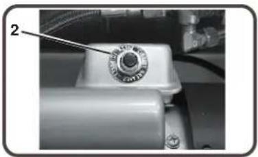
natural_image
Close-up of a mechanical component with a tool inserted, showing a circular housing and mounting holes (no text or symbols visible)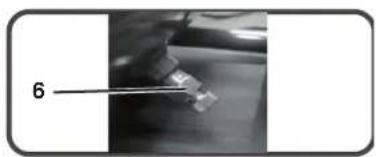
natural_image
Close-up of a gloved hand holding a small object with tweezers, labeled '6' (no text or symbols on the object itself)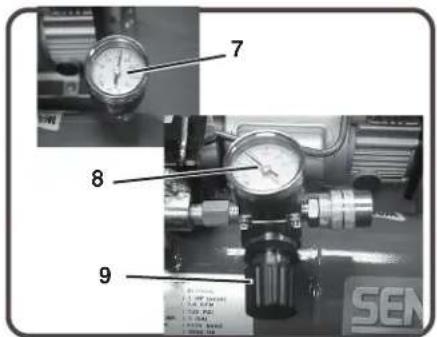
KLARGJ∅RING
MONTERING:
SPARE PARTS LIST
NO:RLB-1311
| REF. NO. | DESCRIPTION | PART NO. | QTY. |
| 1 | Cylinder head | 3101096H | 1 |
| 2 | Allen bolt set | 3B01-M06*080V | 4 |
| 3 | Exhaust elbow | 2N06-02T03HL | 1 |
| 4 | Auto relief valve | 2409003 | 1 |
| 5 | Exhaust valve seat set | 3B11-A9000A | 1 |
| 6 | Cylinder | 3201065 | 1 |
| 7 | Piston rod set | 3B34-MB57 | 1 |
| 8 | Motor set | 3B8-MB5706S | 1 |
| 9 | Filter element | 2142014 | 1 |
| 10 | Shroud | 2428012RS | 1 |
| 11 | Air tank | 3401497QJ | 1 |
| 12 | Rubber pad set | 3433011-ARS | 4 |
| 13 | Drain valve | 2405012 | 1 |
| 14 | Grip | 2432102RS | 1 |
| 15 | Check valve set | 2414036RX | 1 |
| 16 | Unloading tube | 3B2-02*190F | 1 |
| 17 | Exhaust tube | 2T02-03*0260RS | 1 |
| 18 | Pressure switch | 2E21-DA256APS | 1 |
| 19 | Pressure relief valve | 2406021A | 1 |
| 20 | Cable | 2E02-1C30382Y2T | 1 |
| 21 | Hexagon bolt | 3B00-FM08*015RSV | 4 |
| 22 | Quick coupler | 07S1/4M-ERS | 1 |
| 23 | Pressure gauge | 2D12-15D14BAR | 2 |
| 24 | Regulator | 2408008LRS | 1 |
| 25 | Power cable(2pin) | 2E01-029S | 1 |
| 26 | Power cable(3pin) | 2E01-044S | 1 |
| 27 | Running capacitor | 2E27-010F4535 | 1 |
| 28 | Breaker | 2E25-03A | 1 |
SPESIFIKASJONER
| Modell # | PC0968 EU | |
| Motor | ||
| Hestekrefter | 0.54 KW | |
| Spenning | 230 | |
| Ampere 6 | Hz. 50 | |
| Fase | Énfaset | |
| RPM (rotasjoner pr minutt) | 2850 | |
| Kompressorpumpe | Antall sylindere | 1 |
| Komprimeringsnivå | 1 | |
| Veivhus | Aluminium | |
| Lager | Kule | |
| Sylinder | Aluminium | |
| Ventiler | Reed, enkel | |
| Hode | Aluminium | |
| Filter | Utskiftbart | |
| Innstilling for motor-/trykkbryter | Deaktiver | 8.6 bar |
| Aktiver | 6.2 bar | |
| Funksjoner | Start/stopp | |
| Lufttank | Kapasitet | 10 liter |
| Ytelse | Luftfortrenging i CFM | 4 |
| CFM @ 2.8 bar | 1,8 | |
| CFM @ 6.2 bar | 1,4 | |
| Maksimalt trykk | 8.6 bar | |
| Oppumpingstid: 0-8.3 bar | 85 sekunder | |
| Gjenoppumpingstid: | 6.2-8.6 bar | |
| 17 sekunder | ||
| Vekt | Netto | 17.3 kg |
| Dimensjoner | Lengde x bredde x høyde | 40 x 38 x 34 cm |
| FBTVSFE TPVOE QPX FS NFWFM | dBA | |
( VBSBOUFFE□TPVOE□QPXFS□MFWFM□
E#
GARANTI FOR SENCO-KOMPRESSOR OG -DELER
Model PC0968
(E) Skade under transport.
DENNE GARANTIEN ER DEN ENESTE GYLDIGE GARANTIEN FOR DENNE KOMPRESSOREN. ALLE ANDRE GARANTIER ER UGYLDIGE, ENTEN DE ER MUNTLIGE, SKRIFTLIGE, EKSPLISITTE ELLER IMPLISITTE, INKLUSIVE, MEN IKKE BEGRENSET TIL, IMPLISITT GARANTI OM AT PRODUKTET ER EGNET TIL EN BESTEMT BRUK. KJ∅PERS ELLER BRUKERS RETT TIL ERSTATNING ER UTELUKKENDE BEGRENSET TIL OVENNEVNTE. SENCO PRODUCTS, INC., SKAL IKKE UNDER NOEN OMSTENDIGHETER KUNNE AVKREVES ERSTATNING FOR TILFELDIGE, INDIREKTE ELLER SÆRSKILTE SKADER. IKKE UNDER NOEN OMSTENDIGHETER SKAL SENCOS ERSTATNINGSANSVAR OVERSKRIDE PRISEN PÅ DEN KOMPRESSOREN SOM LIGGER TIL GRUNN FOR KRAVET. DETTE GJELDER UAKTET OM BAKGRUNNEN FOR KRAVET ER KONTRAKTSBRUDD, GARANTIBRUDD, IKKE-KONTRAKTSMESSIG ANSVAR (INKLUSIVE UAKTSOMHET) ELLER ANNET. ETHVERT ERSTATNINGSANSVAR FORBUNDET MED BRUKEN AV DENNE KOMPRESSOREN, SKAL OPPH∅RE NÅR GARANTIPERIODEN, SOM ANGITT OVER, UTL∅PER.
natural_image
Exterior view of a Siemens Air Conditioner (CIO-Laser) with two cylindrical units and attached pipes (no visible text or symbols on the device itself)Senco Products, Inc.
8485 Broadwell Rd.
Cincinnati, OH 45244
Bruksanvisning
© 2004 by Senco Products, Inc.
PC0968 Rev. 20-11-2013

INNEHÅLLSFÖRTECKNING
INTRODUKTION 3
VIKTIGT OM SÄKERHET....3
KONTROLL.... 3
SÄKERHETSANVISNINGAR 4
ELEKTRICITET.... 4
EXPLOSION ELLER BRAND.... 5
BRISTNING....5
INANDNING....6
BRÄNNSKADOR....6
FLYGANDE DELAR 6
RÖRLIGA DELAR....7
FÖRSUMLIGHET 7
SKADOR PÅ KOMPRESSORN 7
KOMPRESSORNS FUNKTIONER 8
FÖRBEREDELSER....10
INLEDANDE INSTALLATION....10
PLACERING....10
ELINSTALLATION....10
ANVÄNDNING.... 11
KONTROLLISTA INNAN DU BÖRJAR 11
IGÄNGSÄTTNING.... 11
AVSTÄNGNING....11
UNDERHÅLL 11
FELSÖKNING....12-14
SPECIFICATIONER....15
GARANTI 16
INTRODUKTION
natural_image
Black-and-white icon of a hand with a lightning bolt and smoke, symbolizing electrical hazard (no text or symbols)
natural_image
Warning symbol of a lightning bolt inside a triangle (no text or numbers)EVENTUELL FÖLJI
natural_image
Abstract black-and-white graphic of a stylized human figure with geometric patterns (no text or symbols)RISK FÖR BRANDSKADOR
RISK FÖR FLYGANDE
FÖREMÅL
natural_image
Silhouette of a running person with motion arrows indicating movement (no text or symbols)ANVÄND ALLTID
ÖGONSKYDD

natural_image
Simple icon of a person wearing glasses inside a circle (no text or symbols)EVENTUELL FÖLJI
natural_image
Close-up of a mechanical component with labeled part '1' (no readable text or symbols beyond label)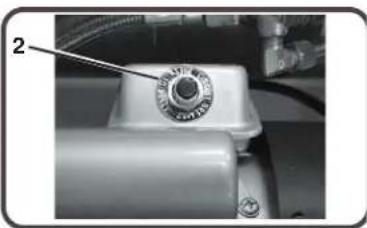
natural_image
Close-up of a mechanical component with a circular knob and attached tubing (no visible text or symbols)
natural_image
Close-up of a mechanical component with a tool inserted, no visible text or symbols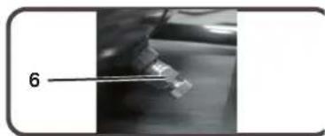
natural_image
Close-up of a mechanical component with a labeled part (6), no visible text or symbols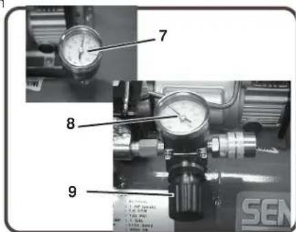
FÖRBEREDELSE
INLEDANDE INSTALLATION:
SPARE PARTS LIST
| REF. NO. | DESCRIPTION | PART NO. | QTY. |
| 1 | Cylinder head | 3101096H | 1 |
| 2 | Allen bolt set | 3B01-M06*080V | 4 |
| 3 | Exhaust elbow | 2N06-02T03HL | 1 |
| 4 | Auto relief valve | 2409003 | 1 |
| 5 | Exhaust valve seat set | 3B11-A9000A | 1 |
| 6 | Cylinder | 3201065 | 1 |
| 7 | Piston rod set | 3B34-MB57 | 1 |
| 8 | Motor set | 3B8-MB5706S | 1 |
| 9 | Filter element | 2142014 | 1 |
| 10 | Shroud | 2428012RS | 1 |
| 11 | Air tank | 3401497QJ | 1 |
| 12 | Rubber pad set | 3433011-ARS | 4 |
| 13 | Drain valve | 2405012 | 1 |
| 14 | Grip | 2432102RS | 1 |
| 15 | Check valve set | 2414036RX | 1 |
| 16 | Unloading tube | 3B2-02*190F | 1 |
| 17 | Exhaust tube | 2T02-03*0260RS | 1 |
| 18 | Pressure switch | 2E21-DA256APS | 1 |
| 19 | Pressure relief valve | 2406021A | 1 |
| 20 | Cable | 2E02-1C30382Y2T | 1 |
| 21 | Hexagon bolt | 3B00-FM08*015RSV | 4 |
| 22 | Quick coupler | 07S1/4M-ERS | 1 |
| 23 | Pressure gauge | 2D12-15D14BAR | 2 |
| 24 | Regulator | 2408008LRS | 1 |
| 25 | Power cable(2pin) | 2E01-029S | 1 |
| 26 | Power cable(3pin) | 2E01-044S | 1 |
| 27 | Running capacitor | 2E27-010F4535 | 1 |
| 28 | Breaker | 2E25-03A | 1 |

SPECIFICATIONER
| Modellnummer | PC0968 EU | |
| Motor | ||
| EffektSpänningStrömstyrka 6 AAntal faserVarvtal | 0.54KW230Hertz 501 (en)2850 | |
| Kompressorpump | Antal cylindrarKompressionskammareVevhusLagerCylinderVentilerLockFilter | 11AluminiumKullagerAluminiumEnkelbladAluminiumInsatstyp |
| Motor/tryckreglageinställning | FrånkopplingInkoppling | 830 kPa620 kPa |
| Reglage | Start/stop | |
| Lufttank | Kapacitet | 10 liter |
| Prestanda | LuftflödeCFM @ 2.8 barCFM @ 6.2 barMaximalt tryckTid till fullt tryck: 0-826 kPaÅterhämtningstid: | 41.81.4830 kPa85 s620-830 kPa17 sekunder |
| Vikt | Netto | 17.3 kg |
| Dimensioner | LxBxH | 400x380x340 mm |
| FBTVSFE TPVOE QPX | dBA | |
( VBSBOUFFE□TPVOE□QPXFS□MFWF□
SENCO KOMPRESSOR- OCH RESERVDELSGARANT
Model PC0968
natural_image
Exterior view of a Siemens CDO-Laser air compressor unit (no signage or text on body)Senco Products, Inc.
8485 Broadwell Rd.
Cincinnati, OH 45244
© 2004 by Senco Products, Inc.
PC0968 Rev. 20-11-2013

KOMPRESSORFUNKTIONER....8
FORBEREDELSE....10
INDLEDENDE INSTALLATION....10
PLACERING....10
ELEKTRISK....10
DRIFT....11
KONTROLLISTE F∅R START 11
OPSTART....11
AFBRYDELSE....11
VEDLIGEHOLDELSE 11
FEJLAFHJÆLPNING....12-14
SPECIFICATIONER....15
GARANTI....16
INDLEDNING
natural_image
Black-and-white icon of a hand with a lightning bolt and a string, symbolizing electrical hazard (no text or symbols)
MULIGE KONSEKVENSEI
1 Motor/Trykafbryder
2 Luftkompressorpumpe
3 Sikkerhedsventil
4 Beholder manometer
5 Aftapningspunkt manometer
6 Trykregulator
7 Afløbsledning
8 Elektrisk netledning
9 Ventilationsåbninger / Beskyttelsesplade
10 Hurtig afbrydelse
11 Luftindsugningsfilter
12 Luftbeholder afløbsventi
13 Cold Start Valve
14 Termisk overbelastning / Nulstil
KOMPRESSORFUNKTIONER
natural_image
Close-up of an electronic component with wires and a labeled part (no readable text or symbols)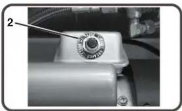
natural_image
Close-up of a mechanical component with a dial indicator and numbered annotation (no readable text or symbols)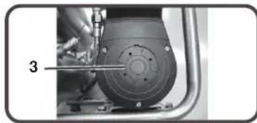
natural_image
Close-up of a mechanical component with a tool inserted, showing a circular component and bolt holes (no text or symbols visible)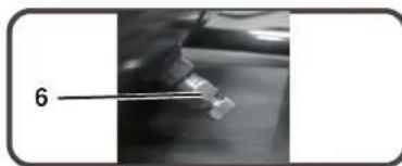
natural_image
Close-up of a hand holding a small object with a labeled arrow pointing to it, against a blurred background (no text or symbols)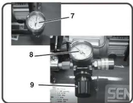
FORBEREDELSE
INDLEDENDE INSTALLERING:
SPARE PARTS LIST
NO:RLB-1311
| REF. NO. | DESCRIPTION | PART NO. | QTY. |
| 1 | Cylinder head | 3101096H | 1 |
| 2 | Allen bolt set | 3B01-M06*080V | 4 |
| 3 | Exhaust elbow | 2N06-02T03HL | 1 |
| 4 | Auto relief valve | 2409003 | 1 |
| 5 | Exhaust valve seat set | 3B11-A9000A | 1 |
| 6 | Cylinder | 3201065 | 1 |
| 7 | Piston rod set | 3B34-MB57 | 1 |
| 8 | Motor set | 3B8-MB5706S | 1 |
| 9 | Filter element | 2142014 | 1 |
| 10 | Shroud | 2428012RS | 1 |
| 11 | Air tank | 3401497QJ | 1 |
| 12 | Rubber pad set | 3433011-ARS | 4 |
| 13 | Drain valve | 2405012 | 1 |
| 14 | Grip | 2432102RS | 1 |
| 15 | Check valve set | 2414036RX | 1 |
| 16 | Unloading tube | 3B2-02*190F | 1 |
| 17 | Exhaust tube | 2T02-03*0260RS | 1 |
| 18 | Pressure switch | 2E21-DA256APS | 1 |
| 19 | Pressure relief valve | 2406021A | 1 |
| 20 | Cable | 2E02-1C30382Y2T | 1 |
| 21 | Hexagon bolt | 3B00-FM08*015RSV | 4 |
| 22 | Quick coupler | 07S1/4M-ERS | 1 |
| 23 | Pressure gauge | 2D12-15D14BAR | 2 |
| 24 | Regulator | 2408008LRS | 1 |
| 25 | Power cable(2pin) | 2E01-029S | 1 |
| 26 | Power cable(3pin) | 2E01-044S | 1 |
| 27 | Running capacitor | 2E27-010F4535 | 1 |
| 28 | Breaker | 2E25-03A | 1 |

SPECIFICATIONER
| Model nr. | PC0968 EU | |
| Motor | ||
| HestekræfterSpændingAmperetal 6FaseOmdrejn. pr. minut | 0.54 KW (spidsbelastning)230Hz. 50Enkelt2850 | |
| Kompressorpumpe | Antal cylindereKompressionstrinKrumtaphusLejerCylinderVentilerHovedFilter | 11AluminiumKugleAluminiumBlad-enkelAluminiumIndsætning |
| Motor/Trykafbryderi ndstilling | UdkoblingTilkobling | 8.6 bar6.2 bar |
| Kontrolfunktioner | Start/stop | |
| Luftbeholder | Kapacitet | 10 liter |
| Ydelse | CFM LuftforskydningCFM ved 2.8 barCFM ved 6.2 barMaksimumtrykOppumpningstid: 0-8.3 barRetableringstid: | 41.81.48.6 bar85 sek.6.2-8.3 bar 17 sekunder |
| Vægt | Netto | 17.3 kg |
| Dimensioner | Basis LxBxH | 40cmx38cmx34cm |
| .FBTVSFE□TPVOE□QP | XFS□MFWFM□ | □□ dBA |
( VBSBOUFFE ▪TPVOE ▪QPXFS ▪MFWFIL
SENCO KOMPRESSOR OG RESERVEDELSGARANTI Model PC0968
CINCINNATI, OHIO 45244-1611, USA
natural_image
Exterior view of a Siemens CIO-Laser air compressor unit (no signage or text on body)Senco Products, Inc.
8485 Broadwell Rd.
Cincinnati, OH 45244
Istruzioni d'Uso
© 2004 by Senco Products, Inc.
PC0968 Rev. 20-11-2013

natural_image
Black-and-white illustration of a hand with a lightning bolt and smoke trail (no text or symbols)
CONSEGUENZE POTENZIAL
natural_image
Close-up of a mechanical component with labeled part '1' (no readable text or symbols beyond label)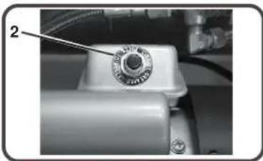
natural_image
Close-up of a mechanical component with a circular knob and attached tubing (no visible text or symbols)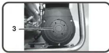
natural_image
Close-up of a mechanical component with a numbered label '3' pointing to a circular feature (no readable text or symbols)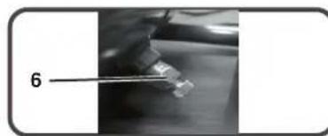
natural_image
Close-up of a hand holding a small object with tweezers, labeled '6' (no other text or symbols visible)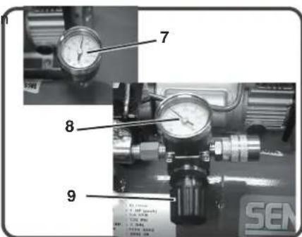
PREPARAZIONE
MONTAGGIO INIZIALE:
SPARE PARTS LIST
NO:RLB-1311
| REF. NO. | DESCRIPTION | PART NO. | QTY. |
| 1 | Cylinder head | 3101096H | 1 |
| 2 | Allen bolt set | 3B01-M06*080V | 4 |
| 3 | Exhaust elbow | 2N06-02T03HL | 1 |
| 4 | Auto relief valve | 2409003 | 1 |
| 5 | Exhaust valve seat set | 3B11-A9000A | 1 |
| 6 | Cylinder | 3201065 | 1 |
| 7 | Piston rod set | 3B34-MB57 | 1 |
| 8 | Motor set | 3B8-MB5706S | 1 |
| 9 | Filter element | 2142014 | 1 |
| 10 | Shroud | 2428012RS | 1 |
| 11 | Air tank | 3401497QJ | 1 |
| 12 | Rubber pad set | 3433011-ARS | 4 |
| 13 | Drain valve | 2405012 | 1 |
| 14 | Grip | 2432102RS | 1 |
| 15 | Check valve set | 2414036RX | 1 |
| 16 | Unloading tube | 3B2-02*190F | 1 |
| 17 | Exhaust tube | 2T02-03*0260RS | 1 |
| 18 | Pressure switch | 2E21-DA256APS | 1 |
| 19 | Pressure relief valve | 2406021A | 1 |
| 20 | Cable | 2E02-1C30382Y2T | 1 |
| 21 | Hexagon bolt | 3B00-FM08*015RSV | 4 |
| 22 | Quick coupler | 07S1/4M-ERS | 1 |
| 23 | Pressure gauge | 2D12-15D14BAR | 2 |
| 24 | Regulator | 2408008LRS | 1 |
| 25 | Power cable(2pin) | 2E01-029S | 1 |
| 26 | Power cable(3pin) | 2E01-044S | 1 |
| 27 | Running capacitor | 2E27-010F4535 | 1 |
| 28 | Breaker | 2E25-03A | 1 |
TROUBLESHOOTING
Guaranteed sound power level [dB] 81 dBA
GARANZIA SENCO PER IL COMPRESSORE E LE SUE PART
Model PC0968
Senco Products, Inc.
8485 Broadwell Rd.
Cincinnati, OH 45244
© 2004 by Senco Products, Inc.
PC0968 Rev. 20-11-2013

natural_image
Black-and-white icon of a hand with a lightning bolt and plug, symbolizing electrical hazard (no text or symbols)
natural_image
Warning symbol of a lightning bolt inside a triangle (no text or numbers)natural_image
Close-up of a mechanical component with labeled part '1' (no visible text or symbols beyond label)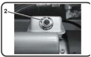
natural_image
Close-up of a mechanical component with a knob and tubing (no visible text or symbols)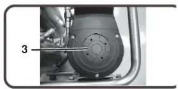
natural_image
Close-up of a mechanical assembly with a numbered component (3) and no visible text or symbols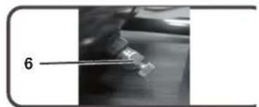
natural_image
Close-up of a mechanical component with a labeled part '6' (no other text or symbols visible)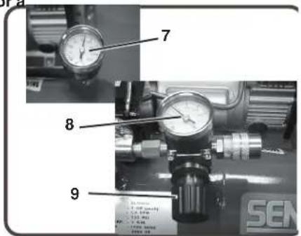
PREPARACIÓN
MONTAJE INICIAL:
SPARE PARTS LIST
NO : RLB-1311
| REF. NO. | DESCRIPTION | PART NO. | QTY. |
| 1 | Cylinder head | 3101096H | 1 |
| 2 | Allen bolt set | 3B01-M06*080V | 4 |
| 3 | Exhaust elbow | 2N06-02T03HL | 1 |
| 4 | Auto relief valve | 2409003 | 1 |
| 5 | Exhaust valve seat set | 3B11-A9000A | 1 |
| 6 | Cylinder | 3201065 | 1 |
| 7 | Piston rod set | 3B34-MB57 | 1 |
| 8 | Motor set | 3B8-MB5706S | 1 |
| 9 | Filter element | 2142014 | 1 |
| 10 | Shroud | 2428012RS | 1 |
| 11 | Air tank | 3401497QJ | 1 |
| 12 | Rubber pad set | 3433011-ARS | 4 |
| 13 | Drain valve | 2405012 | 1 |
| 14 | Grip | 2432102RS | 1 |
| 15 | Check valve set | 2414036RX | 1 |
| 16 | Unloading tube | 3B2-02*190F | 1 |
| 17 | Exhaust tube | 2T02-03*0260RS | 1 |
| 18 | Pressure switch | 2E21-DA256APS | 1 |
| 19 | Pressure relief valve | 2406021A | 1 |
| 20 | Cable | 2E02-1C30382Y2T | 1 |
| 21 | Hexagon bolt | 3B00-FM08*015RSV | 4 |
| 22 | Quick coupler | 07S1/4M-ERS | 1 |
| 23 | Pressure gauge | 2D12-15D14BAR | 2 |
| 24 | Regulator | 2408008LRS | 1 |
| 25 | Power cable(2pin) | 2E01-029S | 1 |
| 26 | Power cable(3pin) | 2E01-044S | 1 |
| 27 | Running capacitor | 2E27-010F4535 | 1 |
| 28 | Breaker | 2E25-03A | 1 |
ESPECIFICACIONES
Guaranteed sound power level [dB] 81 dBA