
MAILA SUB - Subwoofer LD Systems - Free user manual and instructions
Find the device manual for free MAILA SUB LD Systems in PDF.

| Product type | Powered subwoofer |
| Brand | LD Systems |
| Model | MAILA SUB |
| Speakers | 2 x 15" (neodymium magnet woofers, 4"/100 mm voice coil) |
| Amplifier | Class D, 2500 W RMS |
| Frequency response (-6 dB) | 33 Hz (depending on preset) |
| Input impedance | 20 kOhms |
| Line input connector | 1 x locking female XLR |
| Line output connector (Thru) | 1 x male XLR |
| Power supply | PowerCON TRUE1, 100-240 V AC, 50-60 Hz (SMPS) |
| Max power consumption | 1300 W |
| DSP | 24-bit / 48 kHz, 10-band parametric EQ |
| Wireless connectivity | LogoLink (Bluetooth 4.2) for control via MAILA app |
| Display | Backlit graphic LCD screen |
| Controls | Rotary push encoder |
| Indicators | PWR, SIG, LIMIT, PROT LEDs, front LED |
| Enclosure | 18 mm birch plywood, polyurea coating |
| Handles | 6 carrying handles |
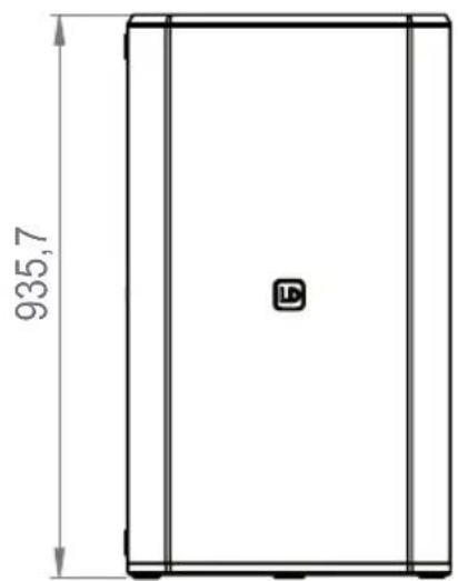
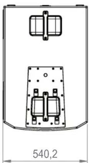
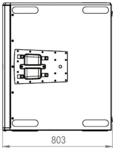
| Dimensions (WxHxD) | 540 x 934 x 803 mm |
| Weight | 90 kg |
| Operating temperature | 0 to 40 °C |
| Relative humidity | < 80%, non-condensing |
| Included accessories | Power cable, user manual |
| Options | Transport cart LDMAILASUBCB, protective cover LDMAILASUBPC |
| Maintenance | Clean with a damp cloth; do not use abrasive products |
| Safety | Overload protection, overtemperature protection, limiting |
Frequently Asked Questions - MAILA SUB LD Systems
User questions about MAILA SUB LD Systems
0 question about this device. Answer the ones you know or ask your own.
Ask a new question about this device
Download the instructions for your Subwoofer in PDF format for free! Find your manual MAILA SUB - LD Systems and take your electronic device back in hand. On this page are published all the documents necessary for the use of your device. MAILA SUB by LD Systems.
USER MANUAL MAILA SUB LD Systems
SAFETY INSTRUCTIONS 4
SCOPE OF DELIVERY 8
PROPERTIES 8
CONSTRUCTION 8
CONNECTIONS, OPERATING AND DISPLAY ELEMENTS 9
SERVICE 11
MAILA APP 15
FIRMWARE UPDATE 16
INDICATION-LED 16
OPTIONAL ACCESSORIES 16
CARE, MAINTENANCE AND REPAIR 16
DIMENSIONS (mm) 17
TECHNICAL SPECIFICATIONS 17
DISPOSAL 19
MANUFACTURER DECLARATION 19
DEUTSCH
ACCESSIONS OPTIONNELS 52
ENTRETIEN, MAINTENANCE ET RÉPARATION 52
DIMENSIONS (mm) 53
This device was developed and manufactured under high quality requirements to ensure many years of trouble-free operation. This is what LD Systems stands for with its name and many years of experience as a manufacturer of high-quality audio products. Please read these operating instructions carefully so that you can quickly and optimally use your new LD Systems product.
You can find more information about LD SYSTEMS on our website www.LD SYSTEMS.COM
ABOUT THIS MANUAL
- Read the safety instructions and the entire manual carefully before starting up.
- Observe the warnings on the device and in the operating instructions.
- Always keep the operating instructions within reach.
- If you sell or pass on the device, be sure to also pass on these operating instructions, as they are an integral part of the product.
INTENDED USE
The product is a device for professional audio installation!
The product has been developed for professional use in the field of audio installation and is not suitable for use in households!
Furthermore, this product is only intended for qualified users with specialist knowledge of dealing with audio installations!
Use of the product outside of the specified technical data and operating conditions is considered improper use!
Liability for damage and third-party damage to persons and property due to improper use is excluded! The product is not suitable for:
- People (including children) with reduced physical, sensory or mental abilities or lack of experience and knowledge.
Children (Children must be instructed not to play with the device).
EXPLANATIONS OF TERMS AND SYMBOLS
- DANGER: The word DANGER, possibly in combination with a symbol, refers to directly dangerous situations or conditions for life and limb.
- WARNING: The word WARNING, possibly in combination with a symbol, refers to potentially dangerous situations or states of life and limb.
- ATTENTION: The word ATTENTION, possibly in combination with a symbol, refers to situations or conditions that can lead to injuries.
- DANGER: The word DANGER, possibly in combination with a symbol, refers to situations or states that can lead to damage to property and/or the environment.
This symbol indicates hazards that can cause an electric shock.

This symbol indicates danger spots or dangerous situations.
This symbol indicates danger from hot surfaces.
This symbol indicates danger from high volumes.

This symbol indicates supplementary information on the operation of the product.

This symbol denotes a device that does not contain any user-serviceable parts.
SAFETY INSTRUCTIONS
DANGER:
- Do not open or modify the device.
- If your device is no longer working properly, liquids or objects have gotten inside the device, or the device has been damaged in any other way, switch it off immediately and disconnect it from the power supply. This device may only be repaired by authorized specialist personnel.
- For devices of protection class 1, the protective conductor must be connected correctly. Never interrupt the protective conductor. Protection class 2 devices do not have a protective conductor.
- Ensure that live cables are not kinked or otherwise mechanically damaged.
- Never bypass the device fuse.
WARNING:
- The device must not be put into operation if it shows obvious signs of damage.
- The device may only be installed in a voltage-free state.
- If the power cord of the device is damaged, the device must not be put into operation.
- Permanently connected mains cables may only be replaced by a qualified person.
DANGER:
- Do not operate the device if it has been exposed to severe temperature fluctuations (e.g. after transport). Humidity and condensation could damage the device. Do not switch on the device until it has reached the ambient temperature.
- Make sure that the voltage and frequency of the mains supply correspond to the values indicated on the device. If the device has a voltage selector switch, do not connect the device until this is set correctly. Only use suitable power cords.
- To disconnect the device from the mains at all poles, it is not enough to press the on/off switch on the device.
- Ensure that the fuse used corresponds to the type printed on the device.
- Make sure that appropriate measures against overvoltage (e.g. lightning) have been taken.
- Note the specified maximum output current on devices with a power out connection. Make sure that the total power consumption of all connected devices does not exceed the specified value.
- Only replace pluggable mains cables with original cables.

DANGER:
- Danger of suffocation! Plastic bags and small parts must be kept out of the reach of people (including children) with reduced physical, sensory or mental abilities.
- Danger from falling! Make sure the device is installed securely and cannot fall. Only use suitable tripods or attachments (especially for fixed installations). Make sure accessories are properly installed and secured. Make sure that the applicable safety regulations are observed.

WARNING:
- Only use the device in the manner intended.
- Only operate the device with the accessories recommended and intended by the manufacturer.
- During installation, observe the safety regulations applicable in your country.
- After connecting the device, check all cable routes to avoid damage or accidents, e.g. B. to avoid tripping hazards.
- Be sure to observe the specified minimum distance to normally flammable materials! Unless this is explicitly stated, the minimum distance is 0.3m .

ATTENTION:
- There is a risk of jamming with moving components such as mounting brackets or other moving components.
- In the case of devices with motor-driven components, there is a risk of injury from the movement of the device. Sudden device movements can lead to startle reactions.

DANGER:
- Do not install or operate the device near radiators, heat registers, stoves or other heat sources. Make sure that the device is always installed in such a way that it is sufficiently cooled and cannot overheat.
- Do not place any sources of ignition such as burning candles near the device.
- Ventilation openings must not be covered and fans must not be blocked.
- Use the original packaging or packaging provided by the manufacturer for transport.
- Avoid shock or shock to the device.
- Observe the IP protection class and the environmental conditions such as temperature and humidity according to the specification.
- Devices can be continuously developed. In the event of deviating information on operating conditions, performance or other device properties between the operating instructions and the device labeling, the information on the device always has priority.
- The device is not suitable for tropical climate zones and for operation above 2000 m above sea level.

ATTENTION:
Connecting signal cables can result in significant noise interference. Make sure that devices connected to the output are muted during plugging. Otherwise, noise levels can cause damage.
ATTENTION HIGH VOLUMES WITH AUDIO PRODUCTS!
This device is intended for professional use.
The commercial operation of this device is subject to the applicable national regulations and guidelines for accident prevention.
Hearing damage due to high volumes and continuous exposure: The use of this product can generate high sound pressure levels (SPL) which can cause hearing damage. Avoid exposure to high volumes.

SIGNAL TRANSMISSION VIA RADIO (e.g. W-DMX or audio radio systems, Bluetooth):
The quality and performance of wireless signal transmissions generally depends on the environmental conditions.
Influence on the range and signal stability, for example:
- Shielding (e.g. masonry, metal structures, water)
High radio traffic (e.g. strong W-LAN networks) - interference
- Electromagnetic radiation (e.g. LED video walls, dimmers)
All range specifications refer to free field use with visual contact without interference!
The operation of transmitters is subject to official regulations. These can vary from region to region and must be checked by the operator before commissioning (e.g. radio frequency and transmission power).

WARNING:
Devices with wireless signal transmission are not suitable for operation in sensitive areas in which radio operation can lead to possible interactions. These include, for example:
- Hospitals, health centers or other healthcare facilities that perform patient treatments with specialized staff and equipment.
Class I, II and III hazardous areas - restricted areas
· military facilities
airplanes or vehicles - Areas where cell phone use is prohibited

NOTES FOR PORTABLE INDOOR DEVICES
- Temporary operation! Event equipment is basically only designed for temporary operation.
- Continuous operation or permanent installation can lead to impairment of the function and premature aging of the devices.
SCOPE OF DELIVERY
Take the product out of the packaging and remove all packaging material.
Check the completeness and integrity of the delivery and please notify your sales partner immediately after purchase if the delivery is incomplete or damaged.
The scope of delivery of the product includes:
- 1x LD MAILA subwoofer
- 1x power cord
- operation manual
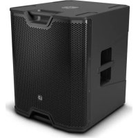
PROPERTIES
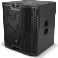
MAILA SUB forms the basis of every MAILA system. The 2.5 kW 2x15" high-performance subwoofer works in bandpass design and, with its newly developed SysCore® DSP, delivers a massive and powerful bass foundation in every application.
The acoustic concept of the MAILA SUB is based on a planar wave bandpass design with a quarter wave horn and a symmetrical driver structure. By arranging the two 15^ speakers opposite each other, the MAILA SUB enables exceptional impulse compensation, which results in powerful and precise low-frequency pressure.
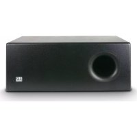
The four large-area bass reflex openings, in conjunction with the housing design, ensure optimized air flow and reduced flow losses, which not only leads to a lower noise level, but above all to higher efficiency at low frequencies.
The housing of the subwoofer consists of 18 mm thick birch plywood with integrated steel braces. The MAIL SUB defies the tough everyday road life with a hard-wearing polyurea finish. A total of six carrying handles ensure optimal grip during assembly and disassembly. The optional MAILA SUB CB roller board is the ideal choice for comfortable transport over long distances.
With LogoLink®, LD Systems has donated another innovation to MAILA. With the free MAILA App (iPadOS), every MAILA system can be adjusted quickly, easily and in detail and wirelessly supplied with software updates. Once connected, the app automatically recognizes the existing MAILA components and enables the system to be optimally set up before and during an event. The highlight: The required wireless antennas are invisibly integrated into the LD logo of the MAILA SUB.

MAILA APP (iPadoS)
The MAILA app for iPadOS is available free of charge in the App Store.

CONSTRUCTION
The subwoofer has 6 ergonomic carrying handles that allow for comfortable transportation. Non-slip rubber rails are located on the bottom and on one side of the housing, so that the subwoofer can be placed both vertically and lying on its side. A connecting plate for the LD MAILA COL speaker column is located on the top of the subwoofer and one on the side opposite the side rubber rails. M20 threads for mounting the LD MAILA DB distance rod and for securing the MAILA COL speaker column are also located in the connecting plates.

DANGER:
Always place the subwoofer in a suitable place on a sufficiently stable, level and horizontal surface. Make sure that the subwoofer or the speaker system cannot fall off the edge of the stage (e.g. due to vibration).
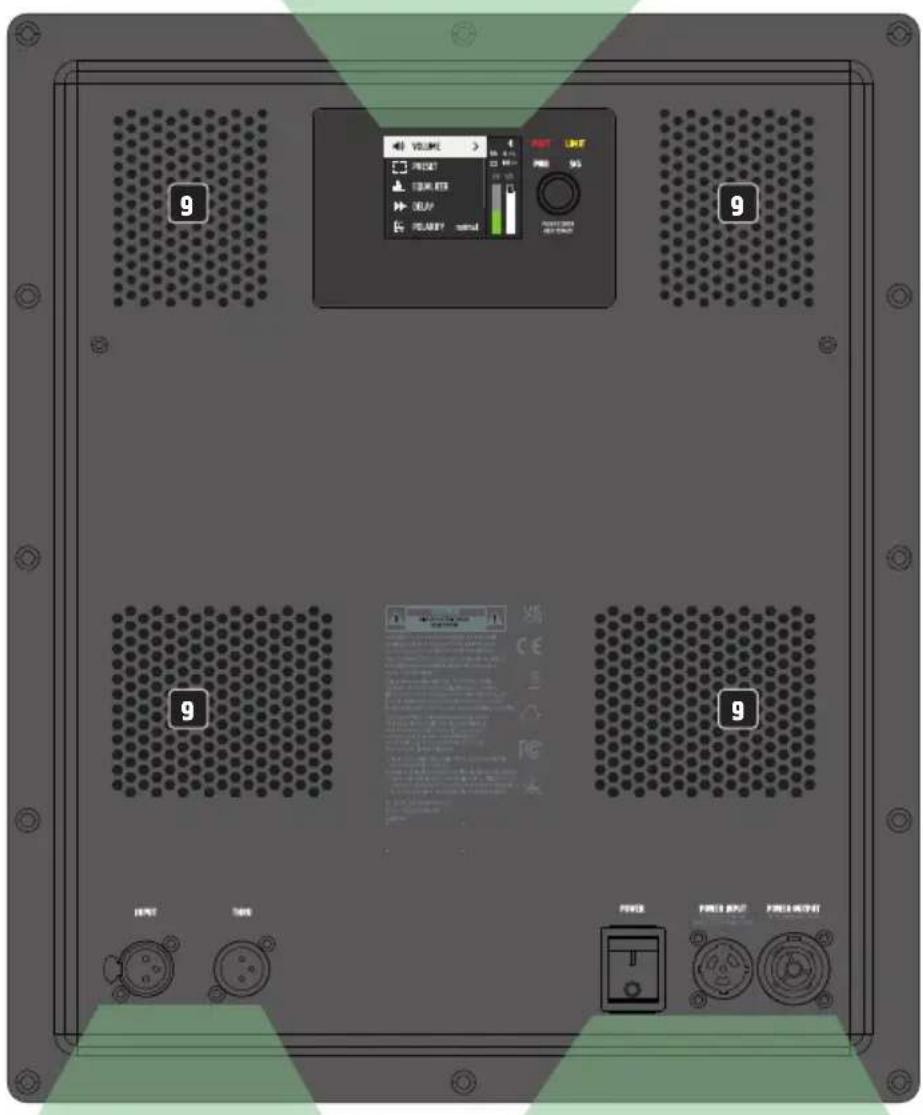
CONNECTIONS, OPERATING AND DISPLAY ELEMENTS
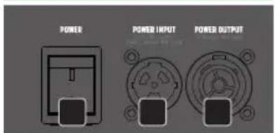
1 POWER INPUT
PowerCON TRUE1 power input jack. A suitable power cord is included in the scope of delivery
2 POWER
On-off switch. Always turn the speaker on as the last device in the signal chain and turn it off as the first device.
3 POWER OUTPUT
The PowerCON TRUE1 mains output socket is used to supply power to other system components. Make sure that the total power consumption of all connected devices does not exceed the value specified in amperes (A) on the device!
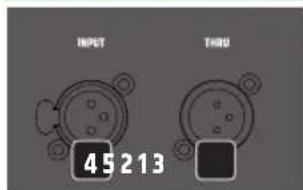
4 INPUT
Balanced line input with locking, female 3-pin XLR socket.
5 THRU
Balanced line output for forwarding the line input signal (male 3-pin XLR socket).
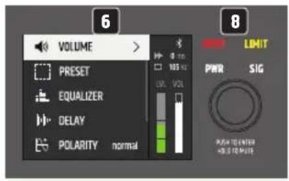
6 LC-DISPLAY
Multifunctional graphic LC display with lighting.
7 PUSH TO ENTER / HOLD TO MUTE
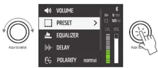
Rotary push encoder for navigating the main menu and submenus and adjusting system settings. Select the individual menu items in the main menu and in the submenus by turning the encoder and confirm the selection by pressing the encoder. Change a numerical value or status in a menu item by turning the encoder and confirm the change by pressing the encoder. To go one level higher in the menu structure, select the arrow symbol < and confirm the selection.
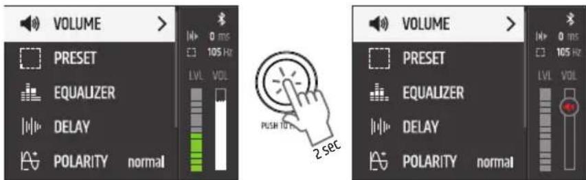
Press the encoder for about 2 seconds to mute the subwoofer and again for about 2 seconds to unmute it.
8 LEDs TO INDICATE DEVICE STATUS
PWR - (Power) The white indicator LED lights up when the device is correctly connected to the mains and switched on.
SIG - (signal) The white indicator LED lights up when an audio signal is present at the device.
LIMIT - (limiter) The yellow indicator LED lights up when the loudspeaker system is operated in the upper limit range. A brief flashing of the LED is not critical. To protect the system, an excessive signal level is gently reduced by the integrated limiter. If the limiter LED lights up longer or stays on, reduce the volume level.
PROT - (Protect) The red indicator LED lights up if the subwoofer is overloaded or overheated. The subwoofer is automatically muted. After reaching normal operating conditions, the device switches back to normal operating mode after a few minutes.
9 VENTILATION OPENINGS
To avoid damage to the device, do not cover the ventilation openings on the back and ensure that air can circulate freely.
SERVICE
HINTS
- When the subwoofer is switched on, all settings such as PRESET and EQUALIZER are loaded as they were before the subwoofer was switched off. The subwoofer is ready for operation after a short time.
- After about 30 seconds without any input via the turn-push encoder, the display system exits Levels in the menu structure and the main display with the selection VOLUME is automatically displayed.
DISPLAY MAIN
In normal operation, the main display is activated, with the main menu, the set delay and the activated preset being displayed. The Bluetooth status, the volume level (LVL) and the gain (VOL) are displayed graphically.
If the top segment of the level display lights up red, this indicates that the input stage is being operated above the distortion limit (clip). Reduce the output level of the playback device (e.g. mixer) until the clip segment no longer lights up and the subwoofer reproduces audio signals without distortion.
VOLUME
To adjust the level of the subwoofer, select VOLUME in the main menu off, confirm, then set the desired value from -40 dB to +10 dB and confirm again.
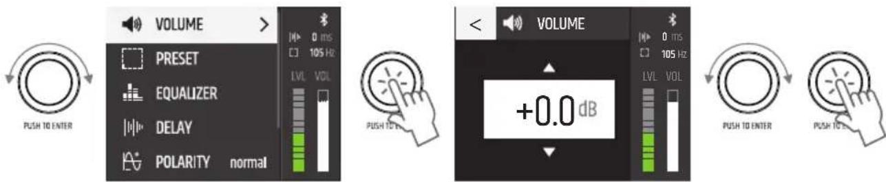
mute: Press the encoder for approximately 2 seconds to mute the subwoofer and again for approximately 2 seconds to unmute (at all menu levels).
PRESET
To set the upper crossover frequency of the subwoofer, select PRESET from the main menu, confirm, then select the desired preset and confirm again. To exit the menu level, select the arrow symbol and confirm your selection.
| PRESET |
| 60Hz |
| 80 Hz |
| 90 Hz |
| 100 Hz |
| 105 Hz |
| 110 Hz |
| 120 Hz |
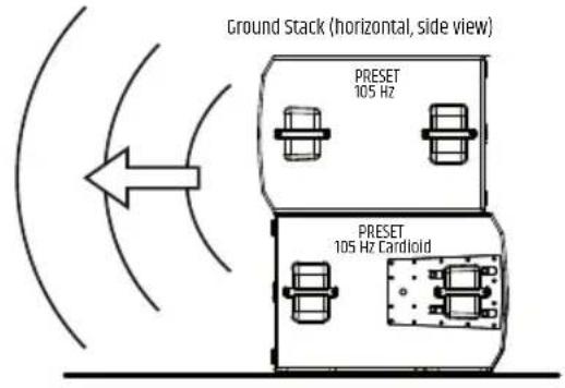
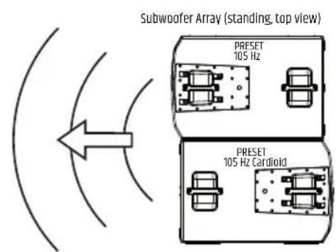
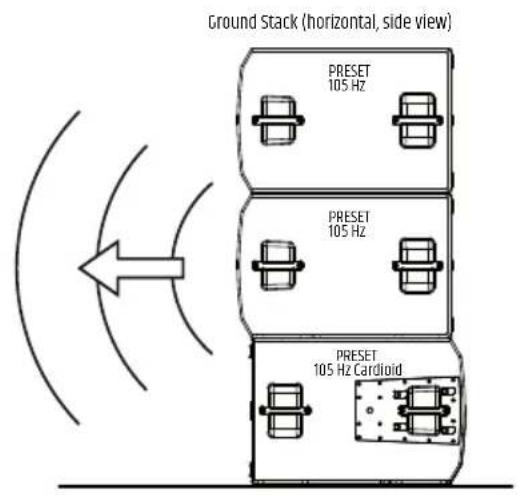
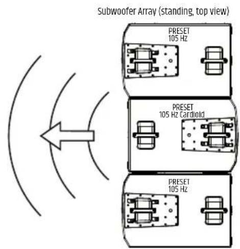
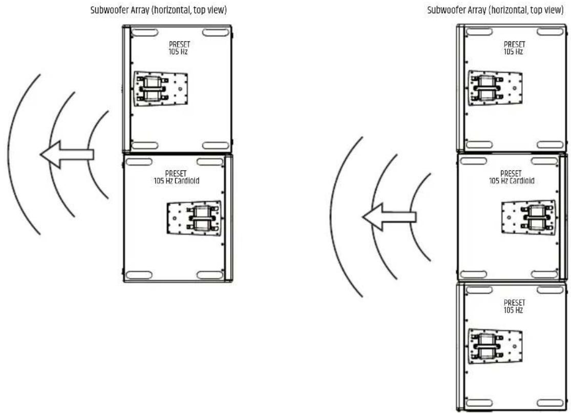
| 105 Hz Cardioid |
With the help of one or two additional subwoofoers (same models, same software version) and the 105 Hz Cardioid preset, a subwoofer array with directional radiation can be realized. The subwoofoers are arranged horizontally, stacked on top of each other (ground stack) and placed upright (standing) or horizontally next to each other (see illustrations).
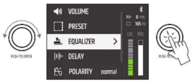
EQUALIZER
The integrated DSP (Digital Signal Processor) has a powerful 10-band fully parametric equalizer. Select EQUALIZER in the main menu and confirm the selection.
The functionality of the equalizer bands 1 and 10 can be set either as fully parametric or as a low shelf (band 1, LS) or hi shelf (band 10, HS).
| EQ ON / OFF | |||
| NR FREQ Q GAIN | |||
| 130 | -20000 0.1 | -10.0 / LS -20 +10 | |
| 230 | -20000 0.1 | -10.0 -20 +10 | |
| 330 | -20000 0.1 | -10.0 -20 +10 | |
| 430 | -20000 0.1 | -10.0 -20 +10 | |
| 530 | -20000 0.1 | -10.0 -20 +10 | |
| EQ ON / OFF | |||
| NR FREQ Q GAIN | |||
| 6 30 - 20000 0.1 - | 10.0 -20 - +10 | ||
| 7 30 - 20000 0.1 - | 10.0 -20 - +10 | ||
| 8 30 - 20000 0.1 - | 10.0 -20 - +10 | ||
| 9 30 - 20000 0.1 - | 10.0 -20 - +10 | ||
| 10 30 - 20000 0.1 - | 10.0 / HS -20 - +10 | ||
To set the frequency in Hertz under FREQ, the Q factor or the functionality of bands 1 and 10 under Q and the amplification in dB under GAIN, select the appropriate column in the desired equalizer band (NR 1-10), confirm and set the value as required and confirm again. The selected value is shown with a white background.
The EQ bands can be disabled individually by selecting and confirming the band number. An X is now displayed in place of a tick symbol and the values in the corresponding band appear grayed out. Select and confirm again to activate the band.
The entire equalizer can be deactivated by selecting the EQ line, confirming, then selecting OFF and confirming again. All values in the equalizer are now greyed out. To activate the equalizer, select ON and confirm. To exit the menu level, select the arrow symbol and confirm your selection.
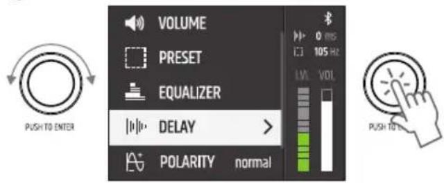
DELAY
To delay the audio signal, select DELAY off, confirm, then select the desired submenu item and confirm again. The value or status can now be set as desired, confirm each entry.
| DELAYTIME x.x ms | ms / m / ft Set delay | lay time in selected delay unit |
| DELAY UNIT ms Delay | delay unit milliseconds | |
| m Delay | Unit Meters | |
| feet Delay | unit feet | |
| TEMPERATURE x °C / °F Set the ambient temperature in the selected temperature unit | ||
| TEMP. UNIT °C Temperature | Temperature unit | Celsius |
| °F Temperature | unit Fahrenheit | |
To exit the menu level, select the arrow symbol and confirm your selection.
POLARITY
To set the polarity of the audio signal, select POLARITY off, confirm, then select the desired status and confirm the selection.
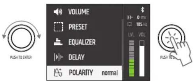
| POLARITY | normal normal | polarity |
| inverted inverted | polarity |
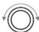
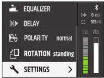
ROTATION
To set the rotation of the display, select ROTATION off, confirm, then select the desired status and confirm the selection.
PUSH TO ENTER
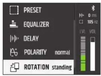

| ROTATION | standing | Subwoofer standing upright |
| horizontal | Subwoofer lying on the side |
SETTINGS
To access the system settings menu, select SETTINGS and confirm the selection. Then select the desired submenu item and confirm the selection.
PUSH TO ENTER

| SYSTEM STATE | SYSTEM STATUS DISPLAY | |
| PIN LOCK * * * * | ← ① Enter PIN code to LOCK | Protect the subwoofer from accidental and unauthorized operation by activating the lock function. Enter a 4-digit PIN and confirm your entry. Access is now only possible after entering the PIN. Reset PIN: Press and hold the encoder while powering on. |
| BLUETOOTH OFF | Bluetooth disabled. | |
| ON | Bluetooth enabled, allowing access to the system via tablet app. | |
| DISPLAY Brightness Setting the display brightness from 10% to 100%. | ||
| Screensaver active | Deactivation of the display lighting after about 1 minute without an entry using the rotary-push encoder. | |
| inactive Display lighting permanently on. | ||
| RESET | FACTORY DEFAULT | Restore factory settings: Select and confirm RESET. |
| RESET | ||
(the illustrations in the device menu may vary slightly depending on the software version)
MAILA APP
Download the MAILA app, which is available free of charge in the App Store, onto your tablet and install it. Activate Bluetooth in the system settings of the active MAILA components. Also activate Bluetooth in the system settings of your tablet and start the MAILA app. The MAILA components with activated Bluetooth within range are now automatically displayed in the MAILA app after a short time.
FIRMWARE UPDATE
Use the MAILA app to check whether new firmware is available for your device. Start the update procedure using the MAILA app. Make sure that there is a stable wireless connection between the device and tablet and do not switch off either the device or the tablet before the update procedure is complete. Aborting the update procedure can lead to device malfunctions. The MAILA app for iPadOS is available free of charge in the App Store.
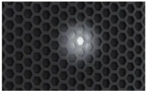
INDICATION-LED
The subwoofer has a white indication-LED on the front behind the front grille. This can be activated for easy identification of the subwoofer using the MAILA app. The MAILA app for iPadOS is available free of charge in the App Store.
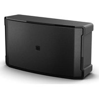
OPTIONAL ACCESSORIES
LDMAILASUBCB (Castor Board)
LDMAILASUBPC (Protective Cover)
CARE, MAINTENANCE AND REPAIR
In order to ensure the perfect functioning of the device in the long term, it must be serviced regularly and serviced if necessary. The need for care and maintenance depends on the intensity of use and the environment.
We generally recommend a visual inspection before each start-up. Furthermore, we recommend all 500 hours of operation, or at the latest after one year in the case of lower usage intensity, to carry out all the below-mentioned and applicable care measures. In the case of defects that can be traced back to insufficient care, the warranty claims may be restricted.
MAINTENANCE (CAN BE CARRIED OUT BY THE USER)
WARNING! Before any maintenance work, the power supply and, if possible, all device connections must be disconnected.

A NOTICE! Improper care can damage the device and even destroy it.
- Housing surfaces must be cleaned with a clean, damp cloth. It is important to ensure that no moisture can penetrate the device.
- Air inlet and outlet openings must be regularly cleaned of dust and dirt. If compressed air is used, care must be taken to prevent damage to the device (eg fans must be blocked in this case).
- Cables and plug contacts must be cleaned regularly and freed from dust and dirt.
- In general, no cleaning agents or agents with an abrasive effect may be used for care, otherwise the surface quality can be expected to be impaired.
- Devices should generally be stored in a dry place and protected from dust and dirt.
MAINTENANCE AND REPAIR (ONLY BY QUALIFIED PERSONNEL)
DANGER! There are live components in the device. Even after the mains connection has been disconnected, there may still be residual voltage in the device, eg due to charged capacitors

A NOTICE! There are no user-serviceable assemblies in the device.

A NOTICE! Maintenance and repair measures may only be carried out by specialist personnel authorized by the manufacturer. If in doubt, contact the manufacturer.

A NOTICE! Improperly performed maintenance work can affect the warranty.
DIMENSIONS (mm)
TECHNICAL SPECIFICATIONS
Item number LDMAILASUB
Product type MAlLA Subwoofer
Type Powered
Woofer dimensions 2 × 15
Woofer magnet Neodymium
woofer brand Custom made
Woofer voice coil 4" /100mm
amplifiers Class D
Item number LDMAILASUB
RMS 2500 W
Frequency response (-6dB) 33Hz - Preset
Protection circuits Limiter, over voltage, over temperature
Input impedance 20k ohms
Controls On/off switch, rotary/push encoder
Indicators LC-Display, Power, Signal, Limit, Protect, Indication LED
Line inputs 1
Line input connectors XLR
Line outputs 1
Line output connectors XLR
Wireless Connectivity LogoLink for App Control
Operating voltage 100-240VAC / 50-60Hz, SMPS
Power consumption (max.) 1300 W
Operating Temperature 0 - 40 °C
Relative Humidity < 80%, not condensing
Cabinet material 18 mm Plywood
Cabinet surface Polyurea
Cabinet construction Quarter Wave Horn Bandpass
handles 6
Width 540mm
Height 934mm
Depth 803 mm
Weight 90 kg
DSP Characteristic
Bit depth AD/DA converter 24 bits
Sampling frequency 48 kHz
Bluetooth
Bluetooth version 4.2
Bluetooth transmission power 9 dBm
Bluetooth frequency range 2402-2480 MHz
DISPOSAL

Packaging:
- Packaging can be fed into the material cycle via the usual disposal routes.
- Please separate the packaging in accordance with the disposal laws and recycling regulations in your country.
Device:
- This device is subject to the European Waste Electrical and Electronic Equipment Directive, as amended. WEEE Directive Waste Electrical and Electronic Equipment. Old devices and batteries do not belong in household waste. The old device or batteries must be disposed of via an approved waste disposal company or a municipal waste disposal facility. Please observe the applicable regulations in your country!
- Observe all disposal laws applicable in your country.
- As a private customer, you can obtain information on environmentally friendly disposal options from the retailer from whom the product was purchased or from the relevant regional authorities.
Batteries and rechargeable batteries:
- Batteries do not belong in household waste. Batteries and accumulators must be disposed of via an authorized waste disposal company or a municipal waste disposal facility.
- Observe all disposal laws and regulations applicable in your country.
- As a private customer, you can obtain information on environmentally friendly disposal options from the retailer from whom the product was purchased or from the relevant regional authorities.
- Devices with batteries or accumulators that cannot be removed by the user must be taken to a collection point for electronic devices.
MANUFACTURER DECLARATION
MANUFACTURER'S WARRANTY & LIMITATION OF LIABILITY
Adam Hall GmbH, Adam-Hall-Str.1, D-61267 Neu Anspach / Email Info@adamhall.com / +49 (0)6081 / 9419-0. For our current warranty terms and limitation of liability see: https://cdn-shop.adamhall.com/media/pdf/MANUFACTURERS-DECLARATIONS LD SYSTEMS.pdf. In the event of service, please contact your sales partner.
UKCA- CONFORMITY
Hereby, Adam Hall Ltd. declares that this product meets the following guidelines (where applicable)
Electrical Equipment (Safety) Regulations 2016
Electromagnetic Compatibility Regulations 2016 (SI 2016/1091)
The Restriction of the Use of Certain Hazardous Substances in Electrical and Electronic Equipment Regulation 2012 (SI 2012/3032)
Radio Equipment Regulations 2017(SI 2016/2015)
UKCA-DECLARATION OF CONFORMITY
Products that are subject to Electrical Equipment(Safety)Regulation 2016, EMC Regulation 2016 or RoHS Regulation can be requested at info@adamhall.com. Products that are subject to the Radio Equip-ments Regulations 2017 (SI2017/1206) can be downloaded from www.adamhall.com/compliance/
FCC STATEMENT
- This device complies with Part 15 of the FCC Rules. Operation is subject to the following two conditions:
(1) This device may not cause harmful interference, and
(2) This device must accept any interference received, including interference that may cause undesired operation.
- Changes or modifications not expressly approved by the party responsible for compliance could void the user's authority to operate the equipment.
RADIATION EXPOSURE STATEMENT
This equipment complies with FCC radiation exposure limits set forth for an uncontrolled environment. This equipment should be installed and operated with minimum distance 20cm between the radiator & your body.
NOTE: This equipment has been tested and found to comply with the limits for a Class B digital device, pursuant to Part 15 of the FCC Rules. These limits are designed to provide reasonable protection against harmful interference in a residential installation. This equipment generates, uses and can radiate radio frequency energy and, if not installed and used in accordance with the instructions, may cause harmful interference to radio communications. However, there is no guarantee that interference will not occur in a particular installation. If this equipment does cause harmful interference to radio or television reception, which can be determined by turning the equipment off and on, the user is encouraged to try to correct the interference by one or more of the following measures:
- Reorient or relocate the receiving antenna.
- Increase the separation between the equipment and receiver.
- Connect the equipment into an outlet on a circuit different from that to which the receiver is connected.
- Consult the dealer or an experienced radio/TV technician for help.
EU DECLARATION OF CONFORMITY
Adam Hall GmbH hereby declares that this radio system type complies with Directive 2014/53/EU. The full text of the EU declaration of conformity is under the following Internet address available: www.adamhall.com/compliance/
Misprints and mistakes, as well as technical or other changes are reserved!
DEUTSCH
ACCESSIONS OPTIONNELS
PUSH TO ENTER / HOLD TO MUTE
Adam Hall GmbH, Adam Hall Straße 1, D-61267 Neu-Anspach
e-mail Info@adamhall.com / +49 (0) 6081/9419-0.
https://cdn-shop.adamhall.com/media/pdf/MANUFACTURERS-DECLARATIONS_LD_SYSTEMS.pdf
www.adamhall.com/compliance/.
DEKLARACJA ZGODNOSCI UE
LDMAILASUBCB (scheda rulli)
Adam Hall Ltd. | The Seedbed Business Centre | SS3 9QY Essex | UK
- DEUTSCH
- ABOUT THIS MANUAL
- INTENDED USE
- EXPLANATIONS OF TERMS AND SYMBOLS
- SAFETY INSTRUCTIONS
- DANGER:
- WARNING:
- ATTENTION:
- ATTENTION HIGH VOLUMES WITH AUDIO PRODUCTS!
- SIGNAL TRANSMISSION VIA RADIO (e.g. W-DMX or audio radio systems, Bluetooth):
- NOTES FOR PORTABLE INDOOR DEVICES
- SCOPE OF DELIVERY
- PROPERTIES
- MAILA APP (iPadoS)
- CONSTRUCTION
- CONNECTIONS, OPERATING AND DISPLAY ELEMENTS
- POWER INPUT
- POWER
- POWER OUTPUT
- INPUT
- THRU
- LC-DISPLAY
- PUSH TO ENTER / HOLD TO MUTE
- LEDs TO INDICATE DEVICE STATUS
- VENTILATION OPENINGS
- SERVICE
- HINTS
- DISPLAY MAIN
- VOLUME
- PRESET
- EQUALIZER
- DELAY
- POLARITY
- ROTATION
- SETTINGS
- MAILA APP
- FIRMWARE UPDATE
- INDICATION-LED
- OPTIONAL ACCESSORIES
- CARE, MAINTENANCE AND REPAIR
- MAINTENANCE (CAN BE CARRIED OUT BY THE USER)
- MAINTENANCE AND REPAIR (ONLY BY QUALIFIED PERSONNEL)
- DIMENSIONS (mm)
- TECHNICAL SPECIFICATIONS
- Item number LDMAILASUB
- DSP Characteristic
- Bluetooth
- DISPOSAL
- Packaging:
- Device:
- Batteries and rechargeable batteries:
- MANUFACTURER DECLARATION
- MANUFACTURER'S WARRANTY & LIMITATION OF LIABILITY
- UKCA- CONFORMITY
- UKCA-DECLARATION OF CONFORMITY
- FCC STATEMENT
- RADIATION EXPOSURE STATEMENT
- EU DECLARATION OF CONFORMITY
- ACCESSIONS OPTIONNELS
- PUSH TO ENTER / HOLD TO MUTE
- DEKLARACJA ZGODNOSCI UE
Brand : LD Systems
Model : MAILA SUB
Category : Subwoofer