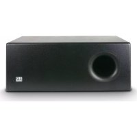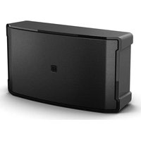
DQOR SUB 8 A - Subwoofer LD Systems - Free user manual and instructions
Find the device manual for free DQOR SUB 8 A LD Systems in PDF.


User questions about DQOR SUB 8 A LD Systems
0 question about this device. Answer the ones you know or ask your own.
Ask a new question about this device
Download the instructions for your Subwoofer in PDF format for free! Find your manual DQOR SUB 8 A - LD Systems and take your electronic device back in hand. On this page are published all the documents necessary for the use of your device. DQOR SUB 8 A by LD Systems.
USER MANUAL DQOR SUB 8 A LD Systems
natural_image
Black rectangular electronic device labeled 'LD' with textured surface and ventilation grille (no other text or symbols visible)CONTENTS / INHALTSVERZEICHNIS / CONTENU / CONTENIDO / TREŚĆ / CONTENUTO
ENGLISH
INFORMATION ON THIS SHORT MANUAL 3
INTENDED USE 3
DEFINITIONS AND SYMBOL EXPLANATIONS 3
SAFETY INSTRUCTIONS 4
INSTRUCTIONS FOR INDOOR
INSTALLATION EQUIPMENT 7
PACKAGING CONTENT 7
INTRODUCTION 8
SET-UP 9
INSTALLATION 9
CONNECTIONS AND OPERATING/DISPLAY ELEMENTS 10
TERMINAL BLOCK CONNECTIONS 13
CARE, MAINTENANCE, AND REPAIR 14
TECHNICAL DATA 15
DISPOSAL 18
MANUFACTURER'S DECLARATIONS 18
DEUTSCH
text_image
QR code image containing encoded data, no visible human-readable textScan this QR Code to get to the download section of DQOR SUB 8 A (W).
Here you can get the complete User manual in the following languages:
EN, DE, FR, ES, PL, IT
https://r.ld-systems.com/01/04049521940644
ENGLISH
This device was developed and manufactured under high quality requirements to ensure many years of trouble-free operation. This is what LD Systems stands for with its name and many years of experience as a manufacturer of high-quality audio products. Please read these operating instructions carefully so that you can quickly and optimally use your new LD Systems product.
You can find more information about LD Systems on our website WWW.LD-SYSTEMS.COM
INFORMATION ON THIS SHORT MANUAL
These instructions do not replace the detailed operating instructions
(https://r.ld-systems.com/01/04049521940644).
Please always read the detailed operating instructions first before operating the unit and observe the additional safety instructions contained therein!
INTENDED USE
The product is a device for professional audio installation!
The product has been developed for professional use in the field of audio installation and is not intended for household use!
Furthermore, this product is intended for installation by qualified personnel with specialist knowledge and for operation by properly trained persons!
Use of the product that is not in accordance with the specified technical data and operating conditions is considered improper use!
Liability is exempted when damage and third-party damage to persons and property is caused by inappropriate use!
The product is not suitable for:
- Use by persons (including children) with limited physical, sensory, or mental abilities or lack of experience and knowledge.
- Children (children must be instructed not to play with the device).
DEFINITIONS AND SYMBOL EXPLANATIONS
- DANGER: The word DANGER, possibly in combination with a symbol, indicates immediately hazardous situations or conditions risking life and limb.
- WARNING: The word WARNING, possibly in combination with a symbol, indicates potentially hazardous situations or conditions risking life and limb.
- CAUTION: The word CAUTION, possibly in combination with a symbol, indicates situations or conditions that may lead to injury.
- ATTENTION: The word ATTENTION, possibly in combination with a symbol, indicates situations or conditions that may lead to damage to property and/or the environment.
This symbol identifies hazards that can cause electric shock.

This symbol indicates hazardous areas or hazardous situations.
This symbol indicates hazards caused by hot surfaces.
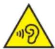
This symbol indicates hazards due to high volume levels.
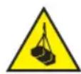
This symbol indicates hazards due to suspended loads.

This symbol indicates a device in which there are no user-serviceable parts.

This symbol indicates additional information on the operation of the product.

This symbol indicates a device that may only be used in dry rooms.
SAFETY INSTRUCTIONS
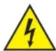
DANGER:
- Do not open the device, and do not make any modifications to it.
- If your device no longer functions properly, if liquids or objects get inside it, or if it has been damaged in any other way, switch it off immediately and disconnect it from the power supply. This device may be repaired only by authorised repair technicians.
- For devices of protection class 1, the protective conductor must be connected correctly. Never disconnect the protective conductor. Devices of protection class 2 do not have a protective conductor.
- Ensure that live cables are not kinked or otherwise mechanically damaged.
- Never bypass the device fuse.
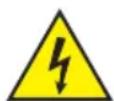
WARNING:
- The device may not be operated if it shows obvious signs of damage.
- The device may only be installed in a voltage-free state.
- If the mains cable of the device is damaged, the device must not be used.
- Permanently attached mains cables may only be replaced by a qualified person.
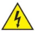
ATTENTION:
- Do not operate the device if it has been exposed to large temperature fluctuations (for example, after transport). Moisture and condensation can damage the device. Switch on the device only when it has reached ambient temperature.
- Make sure that the voltage and frequency of the mains correspond to the values specified on the device. If the device has a voltage selector switch, do not turn the device on until it has been set correctly. Use only suitable mains cables.
- To disconnect the device from the mains on all poles, it is not sufficient to press the on/off switch on the device.
- Make sure that the fuse used corresponds to the type printed on the device.
- Ensure that suitable measures have been taken against overvoltage (for example, lightning strikes).
- Observe the specified maximum output current on devices with a Power Out connection. Ensure that the total current consumption of all connected devices does not exceed the specified value.
- Replace plug-in mains cables with original cables only.

DANGER:
- Danger of suffocation/choking! Plastic bags and small parts must be kept out of reach of persons (including children) with reduced physical, sensory, or mental capabilities.
- Danger caused by falling device! Make sure that the device is securely installed and cannot fall down. Only use suitable stands or mounts (particularly for fixed installations). Ensure that accessories are properly installed and secured. Ensure that all applicable safety regulations are observed.

WARNING:
- Use the device in the prescribed manner only.
- Operate the device only with the accessories recommended and intended by the manufacturer.
- Observe safety regulations applicable in your country during installation.
- After connecting the device, ensure that all cables are routed so as to avoid damage or accidents, such as from tripping.
- Always observe the specified minimum distance to normally flammable materials! Unless explicitly stated, the minimum distance is 0.3 m.

CAUTION:
- Moving components such as mounting brackets pose a jamming hazard.
- In the case of devices with motor-driven components, there is a risk of injury due to the movement of the device. Sudden movement of the device can cause startle reactions.

ATTENTION:
- Do not install or use the device in the vicinity of radiators, accumulators, stoves, or other heat sources. Ensure that the device is always installed in such a way that it is sufficiently cooled and cannot overheat.
- Do not place any ignition sources such as burning candles near the device.
- Ventilation openings must not be covered, and fans must not be blocked.
- For transport, use the original packaging or packaging provided by the manufacturer.
- Avoid any impacts to or shaking of the device.
- Observe the IP rating and the ambient conditions such as temperature and humidity according to the specifications.
- Devices can be continuously further developed. In the event of deviating information on operating conditions, performance, or other device properties between the user manual and the device labelling, the information on the device always takes priority.
- The device is not suitable for tropical climate zones or for operation over 2,000 m above sea level.

CAUTION:
Connecting signal cables can cause significant interference noise. Make sure that devices connected to the output are muted while making connections. Otherwise, noise levels may cause damage.
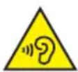
ATTENTION: HIGH-VOLUME AUDIO PRODUCTS!
This device is designed for professional use. The commercial operation of this device is subject to the applicable national regulations and guidelines for accident prevention. Hearing damage due to high volume and continuous exposure: use of this product may generate high sound pressure levels (SPLs) that may cause hearing damage. Avoid exposure to high volumes.

INSTRUCTIONS FOR INDOOR INSTALLATION EQUIPMENT
- Devices for installation applications are designed for continuous operation.
- Devices for indoor installation are not weather-resistant.
- Surfaces and plastic parts can age even in installation equipment, for example, due to UV radiation and temperature fluctuations. This generally does not impair functionality.
- With permanently installed devices, the accumulation of impurities, e.g. dust, is to be expected. Always observe the care instructions.
- Unless explicitly stated otherwise on the device, the devices are intended for installation heights of less than 5 m.
PACKAGING CONTENT
Remove the product from the packaging and remove all packaging material. Please check the completeness and integrity of the delivery and notify your distribution partner immediately after purchase if the delivery is not complete or if it is damaged.
The packaging content for the product LDDQORSUB8A includes:
- 1× DQOR SUB 8 A Subwoofer, Black
- 1 set of terminal blocks
- 1 pair of non-slip rubber feet (pre-assembled)
- Safety and compliance information (user manual as a download via QR code)
The packaging content for the product LDDQORSUB8AW includes:
- 1× DQOR SUB 8 A Subwoofer, White
- 1 set of terminal blocks
- 1 pair of non-slip rubber feet (pre-assembled)
- Safety and compliance information (user manual as a download via QR code)
INTRODUCTION
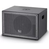
The DQOR® SUB 8 A from the DQOR® Series is an active subwoofer for indoor installation with an 8" woofer and a 10" passive radiator. It has two outputs with 140 W RMS power that have been specially developed for connecting external full-range speakers. These outputs are fine-tuned using the DSP presets to ensure optimum audio pairing with the DQOR® series speakers or any other speaker.
Engineered for high performance with a compact design, it enables a powerful 2.1 audio system without the need for separate amplifier racks.
Its clean, flat design makes the DQOR® SUB 8 A an elegant addition to any room, uniting aesthetics with superior audio performance. Thanks to 250 W RMS, it delivers impressive sound quality with up to 108 dB SPL and an extension of the low frequencies down to 37 Hz.
The DQOR® SUB 8 A has rubber feet for placement on the floor or can be easily installed with the optional surface-mounted bracket. This offers flexible mounting options, holes for neat cable management, locking screws, a safety lock, and a hinge mechanism for quick assembly.
Four terminal strips make balanced stereo input, VCA volume control, and remote control of the standby mode possible. The dip switches can be used to select the stereo/mono mode, the automatic standby mode, and the DSP preset.
The active indoor subwoofer can be used in many different areas, such as in the hospitality industry, in retail, in the entertainment industry, or in companies.
It is available in two colours: black (RAL9005) and white (RAL9016).
FEATURES
- 8" active subwoofer with 10" passive radiator
- Clean, flat design with robust aluminium housing
• 250 W RMS subwoofer performance - 2 × 140 W amplifier for controlling passive speakers for a 2.1 system
- DSP presets for DQOR® speakers or HPF for any speakers
- Optional surface-mounted bracket (wall + ceiling) with hinges for easy installation
SET-UP

Always place the subwoofer in a suitable location on a sufficiently stable, level, and horizontal surface. Do not place the subwoofer, for example, on wall projections from which it could fall, such as due to vibration!
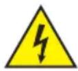
Only connect the subwoofer to the power supply and other devices after it has been set up!
INSTALLATION
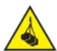
DANGER: Overhead mounting requires extensive experience, including the calculation of the load limit values of the installation material and regular safety inspection of all installation materials and devices. If you do not have these qualifications, do not attempt to perform an installation yourself. Refer instead to a qualified professional. There is a risk that devices that are incorrectly installed and secured and may come loose and fall down. This can cause serious injury or death.

Only use the LD Systems original accessory LDDQORSUB8WMB for wall and ceiling mounting!
Only connect the subwoofer to the power supply and other devices after it has been installed!
CONNECTIONS AND OPERATING/DISPLAY ELEMENTS
text_image
6 VCA 5 SAT OUT 1 2 + C 7 STANDBY 3 LINE IN 1 POWER 2 4 LINE IN 2 + - G 1 POWER IN 100-200V ~ 55-ECHF, FUSE YEA 250V REPLA5 FUSE AS MARKET POWER CONSUMPTION 550V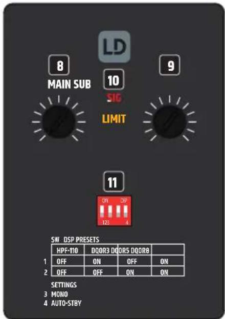
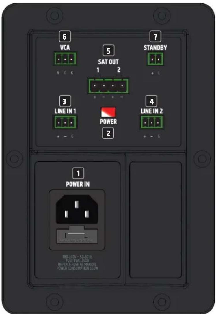
IEC mains socket with integrated fuse holder. A suitable mains cable is included in the packaging content. IMPORTANT NOTE: Only replace the fuse with a fuse of the same type and value. Follow the information printed on the housing. In the event of repeated fuse failure, please contact an authorised service centre.
2 POWER
The power LED illuminates white when the subwoofer is operational. The LED illuminates red when it is in standby mode. If a fault occurs in the system (for example, overtemperature, short circuit), the subwoofer is muted and the LED flashes red (Protect).
3 LINE IN 1
Analogue audio input with a balanced terminal block connection. The +, -, and G poles are for the balanced input signal (suitable for unbalanced cabling). Terminal blocks are included in the packaging content. The input signal from LINE IN 1 is amplified and output to SAT OUT 1. LINE IN 1 and LINE IN 2 are internally summed to mono for the subwoofer signal.
4 LINE IN 2
Analogue audio input with a balanced terminal block connection. The +, -, and G poles are for the balanced input signal (suitable for unbalanced cabling). Terminal blocks are included in the packaging content. The input signal from LINE IN 2 is amplified and output to SAT OUT 2. LINE IN 1 and LINE IN 2 are internally summed to mono for the subwoofer signal.
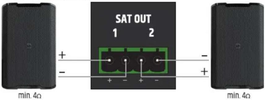
5 SAT OUT 1 / 2
Speaker outputs 1 and 2 for connecting low-impedance satellite speakers (min. 4 ohms).
Please ensure terminal block poles are correctly assigned (see TERMINAL BLOCK CONNECTIONS in this manual). The total power handling of the connected speakers should be approximately equal to the amplifier power.
6 VCA
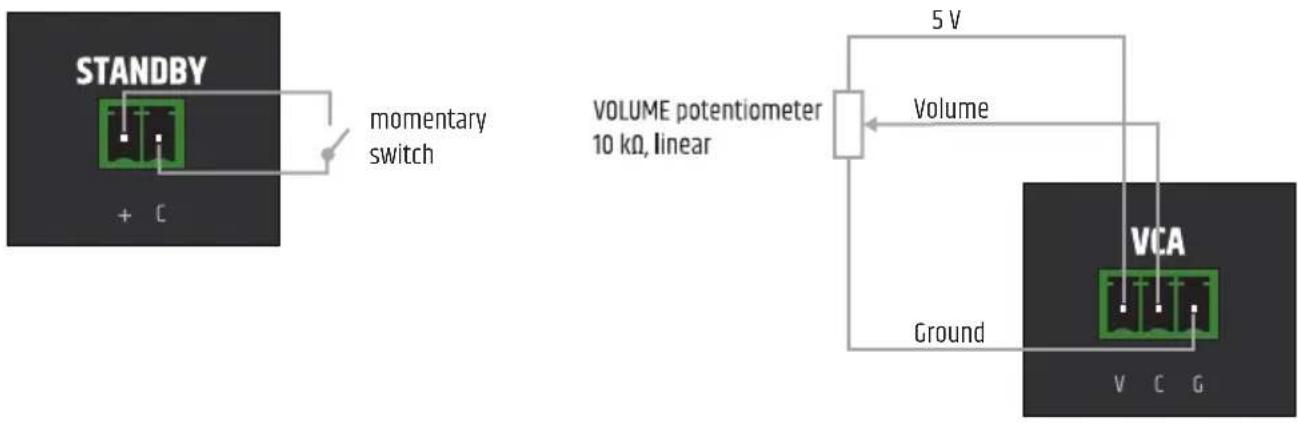
Terminal block connection for the use of an external volume control. Please ensure terminal block poles are correctly assigned (see TERMINAL BLOCK CONNECTIONS in this manual).
7 STANDBY
Standby mode can be activated manually using an external button (momentary switch). Press the button to activate standby mode and mute the subwoofer and speaker outputs. Press the button again to end standby mode. The standby function via an external button has priority over the automatic standby function (see SETTINGS).
8 MAIN
Setting the overall volume (subwoofer and SAT OUT 1 / 2). The subwoofer volume level is controlled by adjusting the SUB level control accordingly. Turning to the right increases the volume, turning to the left decreases it.
9 SUB
Volume control for the subwoofer. Turning to the right increases the volume, turning to the left decreases it.
10 STATUS DISPLAY
SIG: When an audio signal is present at LINE IN 1 and/or LINE IN 2, the signal indicator lights up white. The signal indicator lights up red if the LINE IN 1 and/or LINE IN 2 input stage is pushed beyond its limit. If this occurs, reduce the volume level on the playback device. Failure to do so may result in distorted sound reproduction and damage to the amplifier and speakers.
11 DIP SWITCH 1-4
DSP PRESETS
Switch 1 + 2 OFF: high-pass filter at 110 Hz
Switch 1 ON + Switch 2 OFF: speaker preset for DQOR3
Switch 3 MONO: Set the switch to the ON position to sum the signals from the line inputs LINE IN 1 and LINE IN 2 to mono.
Switch 4 AUTO-STBY: Move the switch to the ON position to activate the device's automatic standby function. If the standby function is activated, the subwoofer system is automatically switched to standby mode if no audio signal is detected for approx. 20 minutes. This reduces energy consumption in a sensible way. As soon as an audio signal is present again, the subwoofer system is automatically powered up from standby mode and is fully operational again within approx. 3 seconds.
The power LED on the back panel lights up red in standby mode. If the power LED lights up white, the device is ready for operation.
TERMINAL BLOCK CONNECTIONS
LINE IN 1 + 2 connections

text_image
balanced LINE IN 1 POWER LINE IN 2 unbalanced + - G + - GSTANDBY connections VCA connections
text_image
STANDBY + C momentary switch VOLUME potentiometer 10 kΩ, linear 5 V Volume Ground VCA V C GSAT OUT 1 + 2 connections
text_image
SAT OUT 1 2 + - + - + - min. 4Ω min. 4Ω
ATTENTION! When wiring terminal blocks, please note the correct assignment of the poles/terminals. The manufacturer accepts no liability for damage caused by faulty wiring!

Tip: For wiring analogue line inputs, it is preferable to use balanced audio cables.
CARE, MAINTENANCE, AND REPAIR
In order to ensure the long-term, proper functioning of the device, it must be regularly cleaned and, if necessary, serviced. The care and maintenance required depends on the intensity of use and the environment in which it is used.
We recommend a visual inspection before each operation. Furthermore, we recommend carrying out all the applicable service measures specified below once every 500 operating hours or, in the case of a lower intensity of use, at the latest after one year. Warranty claims may be limited should defects result from inadequate service and maintenance.
CARE (CARRIED OUT BY USER)
WARNING! Before carrying out any care and maintenance work, the power supply and, if possible, all device connections must be disconnected.

NOTE! Improper care can lead to impairment or even destruction of the device.
- Housing surfaces must be cleaned with a clean, damp cloth. Make sure that no moisture can penetrate the device.
- Air inlets and outlets must be regularly cleaned of dust and dirt. If compressed air is used, make sure that damage to the device is prevented (for example, fans must be blocked in this case).
- Cables and connectors must be cleaned regularly, and dust and dirt must be removed.
- In general, no cleaning or disinfection agents or abrasive agents may be used, as they may damage the surface finish. Solvents in particular, such as alcohol, can impair the function of housing seals.
- Devices must generally be stored in a dry environment and protected from dust and dirt.
MAINTENANCE AND REPAIR (BY QUALIFIED PERSONNEL ONLY)
DANGER! There are live components in the device. Even after disconnecting from the mains, there may still be residual voltage in the device, for example, due to charged capacitors.

PLEASE NOTE! There are no user-serviceable assemblies in the device.

NOTE! Maintenance and repair work may only be carried out by sufficiently qualified specialist personnel. If in doubt, consult a specialist workshop.

NOTE! Improperly performed maintenance work may affect warranty claims.

PLEASE NOTE! For conversion or retrofit sets provided by the manufacturer, it is essential to observe the enclosed installation instructions.
TECHNICAL DATA
Product number LDDQORSUB8A
General information
Directional characteristic Omnidirectional
RMS output power 250 W
Amplifier class Class D
SPL (1 W/1 m) 86 dB
Max. SPL peak (Sine Burst, 110 dB
Half-space/1 m, THD ≤10%)
Max. SPL peak (Pink Noise, 119 dB)
Half-space/1 m, CF 4)
Frequency response (-3 dB, rel. avg) 43 Hz
Frequency response (-10 dB, rel. avg) 37 Hz
Transition frequency 200 Hz
Protection functions Soft start, short circuit, overheating, overvoltage, undervoltage, direct current
Colour Black or White
Inputs
Number of line inputs 2
Line-in connection type 3-pin terminal strip / 3.81 mm pitch
Line inputs
Nom. Sensitivity (< 1% THD, 1 kHz) 0 dBu
Nom. Input clipping 19 dBu
Impedance 16 kΩ
Min. CMRR (0 dBu, mid. volume, 1 kHz) 50 dB
Outputs
Output signal types Loudspeakers/speakers
Number of speaker outputs 2
Speaker output connection type 4-pin terminal strip / 5.08 mm pitch
Min. speaker impedance 40
Signal processing
Bit depth of AD/DA converter 24 bit
Sample rate of AD/DA converter 48 kHz
Min. signal-to-noise ratio (SNR) 96 dB
System latency 2 ms
Amplifier
| Number of satellite outputs 2 | |
| Satellite output power per channel (RMS) | 25 W |
| Sub output power per channel (RMS) | 125 W |
| Satellite output power per channel (Peak) | 45 W |
| Sub output power per channel (Peak) | 180 W |
| Max. THD+N (SAT out, 0 dBu, Volume Centre, 1 kHz, 20 kHz BW) | 0.01% |
| Max. THD+N (SUB out, 0 dBu, Volume Centre, 63 kHz, 20 kHz BW) | 0.02% |
External control
| Resistor for volume control (VCA) 10 kΩ |
| VCA input connection socket 3-pin terminal strip / 3.81 mm pitch |
| GPI-controllable functions Standby |
| GPI input connection socket Terminal strip 2-pin / pitch 3.81 mm |
Woofer
| Size 8" |
| Magnet Ferrite |
| Voice coil 2.5" |
| Passive diaphragm 10" |
Mains operation
| Operating voltage 100 V AC - 240 V AC (±10%) / 50 - 60 Hz | |
| Power consumption 550 W | |
| Power consumption in idle mode 25 W | |
| Max. power consumption in standby mode | 0.5 W |
| Power supply type Switching power supply (SMPS) | |
| Inrush current | 2.7 A |
| Mains connection | IEC C14 socket |
| Fuse | T6.3AL / 250 V |
Standby
Auto standby after 20 min.
Wake-up time in standby mode 3 s
Wake-up threshold -54 dBFS
Housing
Type Closed with passive diaphragm
Housing material Die-cast aluminium, plastic
Front grille material Aluminium
Cooling
Cooling system Convection cooling
Ambient conditions
Maximum humidity < 85% (non-condensing)
Safety class Class 1
Dimensions and weight
Width 537.4 mm
Height 304.4 mm
Depth 185.6 mm
Weight 15.2 kg
DISPOSAL

Packaging:
- Packaging can be fed into the reusable material cycle using the usual disposal methods.
- Please separate the packaging in accordance with the disposal laws and recycling regulations in your country.
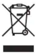
Device:
- This device is subject to the European Directive on Waste Electrical and Electronic Equipment, as amended. WEEE Directive Waste Electrical and Electronic Equipment. Waste equipment and batteries do not belong in household waste. Waste equipment or batteries must be disposed of via an authorised waste disposal company or a municipal waste disposal facility. Please observe the applicable regulations in your country!
- Observe all disposal laws applicable in your country.
- As a private customer, you can obtain information on environmentally friendly disposal options from the seller of the product or the appropriate regional authorities.
MANUFACTURER'S DECLARATIONS
MANUFACTURER'S WARRANTY AND LIMITATION OF LIABILITY
Adam Hall GmbH, Adam-Hall-Str. 1, D-61267 Neu-Anspach / Email Info@adamhall.com / +49 (0)6081 / 9419-0. Our current warranty conditions and limitation of liability can be found at: https://cdn-shop.adamhall.com/media/pdf/MANUFACTURERS-DECLARATIONS_LD_SYSTEMS.pdf. For service requests, please contact your distribution partner.
CE CONFORMITY
Adam Hall GmbH hereby confirms that this product meets the following guidelines (where applicable): Low-Voltage Directive (2014/35/EU) EMC Directive (2014/30/EU) RoHS (2011/65/EU) RED (2014/53/EU)
EC DECLARATION OF CONFORMITY
Declarations of conformity for products subject to the LVD, EMC, and RoHS Directives can be requested from info@adamhall.com. Declarations of conformity for products subject to RED can be downloaded from www.adamhall.com/compliance/.
Subject to misprints and errors, as well as technical or other modifications!