VKM1800.0SR - Hob Küppersbusch - Free user manual and instructions
Find the device manual for free VKM1800.0SR Küppersbusch in PDF.
User questions about VKM1800.0SR Küppersbusch
0 question about this device. Answer the ones you know or ask your own.
Ask a new question about this device
Download the instructions for your Hob in PDF format for free! Find your manual VKM1800.0SR - Küppersbusch and take your electronic device back in hand. On this page are published all the documents necessary for the use of your device. VKM1800.0SR by Küppersbusch.
USER MANUAL VKM1800.0SR Küppersbusch
natural_image
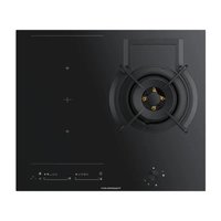
Four white circles arranged in a 2x2 grid on a black background (no text or symbols)VKM1800.0
text_image
KüppersbuschPlease read the users an installation instructions carefully before installation of the appliance and before starting to use.
natural_image
Pure technical line drawing of a curved structural component with an arrow indicating downward direction (no text or symbols)natural_image
Mechanical assembly diagram showing two vertical prisms with labeled components (a, b, c, d, e), no text or symbols present.Zu Punkt c
natural_image
Close-up of hands handling a white plastic roller or tape, no visible text or symbolsWichtig:
natural_image
Three 3D-rendered metallic objects: a curved bracket, a rounded rectangular cutout, and a rectangular prism with the label 'oder' (no other text or symbols)b
natural_image
Three gray 3D geometric shapes: a curved pipe elbow, a rectangular prism, and a rectangular block, with no text or symbols present.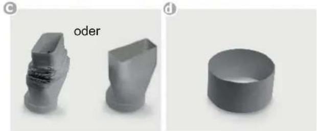
natural_image
Three 3D geometric shapes: a block-like structure, a rounded rectangular prism, and a cylindrical ring, all labeled with 'oder' in the top-left corner (no other text or symbols)
natural_image
Exterior view of a mechanical device with a circular component and a black connector, labeled 'Lüfter' (no other text or symbols visible)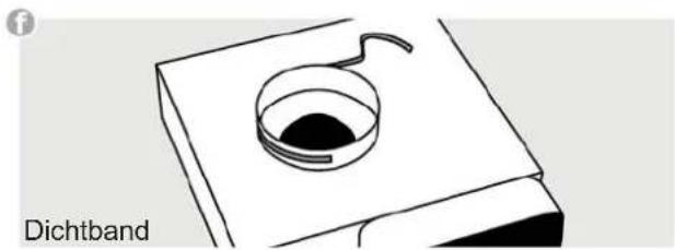
natural_image
Simple line drawing of a Dichtband device with a circular component on top (no text or symbols on the device itself)Sockelfi Iter (optional)
g
natural_image
3D model of an Aktivkohlefi Inter component (no text or symbols on the object itself)1.1 For your information....14
1.2 Intended use 14
2 Safety Instructions and Warnings 15
2.1 For connection and operation .....15
2.2 General information on the hob 15
2.3 For persons 16
2.4 Explanation for symbols and indications .....17
3 Using the fan 18
3.4.1 Switching the fan on and off 18
3.4.2 Fan time lag 18
3.4.3 Stop delay time 18
4 Cleaning and care 19
4.1 Hob fan ....19
5 Instructions for assembly 20
5.1 Safety instructions for kitchen unit fi tters .....20
5.2 Installation 20
5.3 Extraction air system assembly .....22
5.4 7-pole fan plug connector ....23
5.5 Hob fan installation 23
6 Decommissioning and disposal f the appliance 24
6.1 Switching the appliance off completely .....24
6.2 Disposing of the packaging 24
6.3 Disposing of old appliances 24
1. General
1.1. For your information...
Please keep this manual in a safe place and pass it on to new owners for their information and safety.
1.2. Intended use
The fan has been designed for installation next to a suitable hob. It is electronically connected to the hob.
Only the fans and hobs authorised by Küppersbusch may be installed together.
2. Safety Instructions and Warnings
2.1. For connection and operation
- The appliances are constructed in accordance with the relevant safety regulations.
- Connecting the appliances to the mains and repairing and servicing the appliances may only be carried out by a qualified electrician according to currently-valid safety regulations. For your own safety, do not allow anyone other than a qualified service technician to install, service or repair the product.
- If the mains supply cable of this appliance is damaged, it has to be replaced by the manufacturer, the Customer Service of the manufacturer or by another qualified person to avoid danger.
- The appliance may not be operated with an external timer or an external telecontrol system.
2.2. General information on the hob
- Never allow the induction hob to operate unattended, as the high power setting results in extremely fast reactions.
- When cooking, pay attention to the heat-up speed of the cooking zones. Avoid boiling the pots dry as there is a risk of the pots overheating!
- Do not place empty pots and pans on cooking zones which have been switched on.
• Take care when using simmering pans as simmering water may dry up unnoticed, resulting in damage to the pot and to the hob for which no liability will be assumed. - It is essential that after using a cooking zone you switch it off with the respective minus key and not just with the pan recognition device.
• Overheated fats and oils may spontaneously ignite. Always supervise the preparation of food with fats and oils. Never extinguish ignited fats and oils with water! Switch the appliance off and then carefully cover the flame, for example with a lid or an extinguisher blanket. - The glass ceramic surface of the hob is extremely robust. You should, however, avoid dropping hard objects onto the glass ceramic
hob. Sharp objects which fall onto your hob might break it.
- There is a risk of electric shocks if the glass ceramic hob develops fractures, cracks, tears or damage of any other kind. Immediately switch off the appliance. Disconnect the fuse immediately and call Customer Service.
- If the hob cannot be switched off due to a defect in the sensor control immediately disconnect your appliance and call Customer Service.
• Take care when working with home appliances! Connecting cables must not come into contact with hot cooking zones. - Risk of fire: never store items on the hob.
- The glass ceramic hob should not be used as a storage area.
- Do not put aluminium foil or plastic onto the cooking zones. Keep everything which could melt, such as plastics, foil and in particular sugar and sugary foods away from hot cooking zones. Use a special glass scraper to immediately remove any sugar from the ceramic hob (when it is still hot) in order to avoid damaging the hob.
- Metal items (pots and pans, cutlery, etc.) must never be put down on the induction hob since they may become hot. Risk of burning!
- Do not place combustible, infl ammable or heat deformable objects directly underneath the hob.
- Metal items worn on your body may become hot in the immediate vicinity of the induction hob. Caution! Risk of burns! Non-magnetisable objects (e.g. gold or silver rings) are not affected.
- Never use the cooking zones to heat up unopened tins of food or packaging made of material compounds. The power supply may cause them to burst!
- Keep the sensor keys clean since the appliance may consider dirt to be fi nger contact. Never put anything (pans, tea towels etc.) onto the sensor keys!
-
If food boils over onto the sensor keys, we advise you to activate the OFF key.
-
Hot pans and pots should not cover resp. be moved to close to the sensor keys, since this will cause the appliance to switch off automatically.
- Place the pan as close to the centre of the cooking zone as possible.
- Whenever possible, use the back cooking zones for large pans so that the sensor keys are not heated up too much (touch control overheating; error message E2, touch control cut off).
- Activate the childproof lock if there are any pets in the home which could make contact with the hob.
- The induction hob may not be used when pyrolysis operation is taking place in a built-in oven.
- Never clean the glass ceramic hob with a steam cleaner or similar appliance!
- Make sure there are no items (e.g. cleaning cloths) right next to the hob extractor. They could be sucked in by the air current. Liquids and small items must always be kept away from the appliance.
- Never operate the appliance without installing a filter.
- Filter with too much fat deposits causes fi re hazard!
- Constant supervision is essential when deep-frying; fl ambéing is not permitted.
- A sufficient supply of inlet air must be provided when operating wood, coal, gas or oil heaters requiring a chimney. The permissible negative pressure which results from the hood in the location of the heaters requiring a chimney may not exceed 4 Pa (0.04 mbar) as this results in a risk of poisoning.
- Vapour also emits moisture into the air in the kitchen during the cooking process.
- Only a little moisture is removed from the vapours in the convection air mode. This is why a sufficient supply of fresh air must always be provided, e.g. by opening the window or using domestic ventilation systems.
• Always make sure that the indoor climate is normal and comfortable (45 - 60 % humidity).
- Switch the hob extractor down to a lower setting for around 20 minutes or activate the automatic delayed stop function every time the hob extractor is used in the convection air mode.
2.3. For persons
- These appliances may be used by children aged 8 years and over and by persons with physical, sensory or mental impairments or by persons who lack experience and/or know-how, provided they are supervised or have been instructed in the safe used of the appliance and have understood the risks relating to the appliance. Children may not play with the appliance. Cleaning and maintenance by the user may only be carried out by children when they are supervised.
- The surfaces of the heating and cooking zones become hot during use. Keep small children away at all times.
- Only hob protective grids and hob covers produced by the hob manufacturer or the manufacturers of the hob protective grids and hob covers authorised by the manufacturer in the instructions for use may be used. The use of unsuitable hob protective grids and hob covers may result in accidents.
- Persons with cardiac pacemakers or implanted insulin pumps must make sure that their implants are not affected by the induction hob (the frequency range of the induction hob is 20-50 kHz).
2.4. Explanation for symbols and indications
The appliance was produced according to state of the art technology. Machines nevertheless give rise to risks which cannot be constructively avoided.
In order to guarantee sufficient safety for the use, safety instructions are also given. These instructions are marked by way of the highlighted texts which follow.
Sufficient safety in operation will only be guaranteed when these instructions are observed.
The designated text passages have different meanings:
DANGER
Note indicating an imminent threat which may result in death or very serious injury.
CAUTION
Note indicating a potentially dangerous situation which may result in death or very serious injury.
IMPORTANT
Note indicating a dangerous situation which may result in minor injury or damage to the appliance.

PLEASE NOTE
Note to be observed in order to make handling the appliance easier.
The following danger symbols are used at some points:
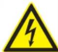
WARNING OF ELECTRICAL ENERGY RISK OF FATAL INJURY!
Live components have been installed near this symbol. Covers bearing this sign may only be removed by a certifi ed skilled electrician.
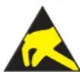
OBSERVE REGULATIONS FOR HANDLING ELECTROSTATICALLY SENSITIVE COMPONENTS AND MODULES (ESDS).
Electrostatically endangered components and modules are located behind covers bearing the adjacent symbol. Never touch plug connections, strip conductors or component pins. Only qualified staff members who are familiar with ESDs are authorised to carry out any technical intervention work.
text_image
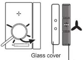
Glass coverThe open cover does not need to be removed.
text_image
2. □─┐│→ │ ┌│
text_image
Diagram showing a hand holding a square with an '人' (person) and plus sign, followed by an arrow pointing to a rectangle labeled '3'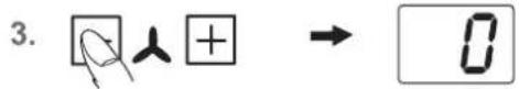

text_image
1. min → 9'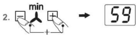
text_image
2. min → 59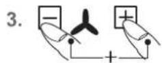
3. Using the fan
The ventilator keys are on the right side of the touch control panel.
Remove the glass cover before initial operation of the fan. The cover does not need to be removed from models with an open cover.
Important:
Do not put the cover down onto the induction hob! Risk of burning!
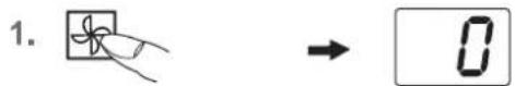
3.4.1 Switching the fan on and off
- Press the fan ON/OFF key (approx. 1 s.)
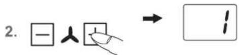
- Press the fan Plus key 44 s.).
You will then be able to select a power setting, 1,2,3 or 4, by using the Plus ☑ Minus key . The symbol for the fan will light up.
The intensive power setting 4 operates for 10 minutes, after which the power level is automatically reduced to power setting 3.
- Press the fan Minus key until 0 is shown in order to switch fan off.
Hint
In order to ensure that extraction functions well with tall cooking pots (e.g. pots used for cooking asparagus), you can place a wooden spoon under the lid of the pot.
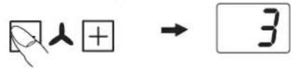
3.4.2 Fan time lag
The fan time lag is used after cooker in order to remove cooking odours. The filter is also dried in the fan.
- Press simultaneously the fan Plus key and Minus key
- The fan time lag of 10 minutes will be activated. The symbol for the fan time lag will light up min
- Pressing simultaneously again the Plus- and Minus key will set 60 minutes.
- The time lag function is deactivated by pressing the two keys simultaneously again.
The fan setting can be freely adjusted or changed when the fan time lag is switched on.
3.4.3 Stop delay time
The fan motor should continue operating for another 10-20 minutes every time the hob has been used for cooking. When the fan is switched off after having been in operation for at least 15 minutes, an automatic time lag at a low setting will follow for around 15 minutes.
This guarantees optimal functioning and the removal of remaining cooking steam.
When using a recirculating air filter, please always allow for a stop delay time of 10 - 60 minutes in order to optimally remove cooking odours.
When the fan is switched on again, in rare cases the odour molecules present in the filter may be combined with steam so that they are detected again. These remaining odours will disappear when the fan continues to operate.
Important
When the convection air mode is in operation, ventilation must be sufficient in order for the air humidity to be removed.
4. Cleaning and care
4.1. Hob fan
Cleaning the metal grease fi Iters
Clean the metal grease filters in the dishwasher or in mild soapy water at least once a month or in the event of excessive grease deposits and/or intensive use.
To remove the fi liter, lift up the fan cover and lift the U-shaped stainless steel ventilation plate in the suction intake opening upwards to remove it from the fan. Now remove the fi liter. To do so, press the lock in the recessed handle downwards and remove the fi liter.
The fi liter can be rinsed in a dishwasher. Stand the fi liter upright in the dishwasher. Please use only rinse aid that is suitable for use with aluminium in order to avoid damaging and discolouring the fi liters.
Never rinse right next to glasses or light-coloured porcelain.
Do not operate the fan without grease fi Iters!
After rinsing the fi Iter, dry it and replace it in the fan. Please make sure that the recessed handle is visible after you have replaced the fi Iter. If possible, wipe the easily accessible inside of the fan with a cloth dampened with detergent every time you replace a fi Iter, while at the same time paying attention to protruding parts in the inside of the fan.
Fan cleaning and care
The fan is best cleaned every time you clean the fi lters. Condensation water may collect under the fi lter after water has boiled rapidly with the lid of the pot removed. This is quite normal. The water should, however, be removed and the inside of the fan cleaned.
The ventilation openings in the cover ensure that residual moisture resulting from cooking and cleaning can escape if necessary when the fan is not in operation and the cover is on.
Please clean the filter and the inside of the fan if unpleasant remaining odours escape.
The fan is best cleaned with a soft damp cloth and mild soapy water.
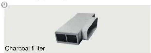
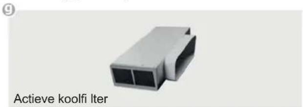
Service
The filter must remain accessible. Replace the charcoal filter mats of a charcoal filter every 5 to 24 months.
5. Instructions for assembly
5.1. Safety instructions for kitchen unit fi tters
- Veneers, adhesives and plastic surfaces of surrounding furniture must be temperature resistant (at least 75^ ). If the veneers and surfaces are not sufficiently heat resistant they may become deformed.
- Ensure that all live connections are safely insulated when installing the hob.
- Cover strips between the wall and the worktop behind the hob which are made of solid wood are permissible as long as minimum clearances in accordance with the installation diagrams are maintained.
- Minimum clearances of the hob cut-out towards the rear are to be maintained in accordance with the installation diagram.
- For installation directly next to a tall cupboard, a safety distance of at least 50 mm must be ensured. The side surface of the tall cupboard should be fitted with heat resistant material. Due to working requirements, however, the distance should be at least 300 mm.
- The clearance between the hob and an extraction hood must be at least as large as that stipulated in the assembly instructions for the cooker hood.
- The packaging materials (plastic foil, polystyrene, nails etc.) must be kept out of reach of children as these parts are potentially dangerous. Small parts can be swallowed and there is a danger of plastic sheeting causing suffocation.
5.2. Installation
Important information
- Avoid excessive thermal development from below e.g. from a baking oven without a cross flow cooling device.
- The induction hob may not be used when pyrolysis operation is taking place in a built-in oven.
- When installing the appliance on top of a drawer it is essential to ensure that no sharp items are stored in the drawer since these could become bent on the underside of the hob and prevent the drawer from being opened and closed.
- If a shelf has been inserted underneath the hob, there must be a clearance of at least 20 mm to the underside of the hob in order to ensure that the hob is sufficiently ventilated.
- The hob may not be installed above refrigerators, free-zers, dishwashers, washing machines or dryers.
- To avoid danger of fi re, make sure that no combustible objects which could easily catch fi re or become deformed on exposure to heat are directly next to or under the surface.
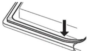
Sealing of the hob
Before installation, correctly insert the sealing unit delivered with the hob.
natural_image
Pure technical line drawing of a curved mechanical component with an arrow indicating downward motion (no text or symbols)- No liquids may penetrate between the edge of the hob and the worktop or between the hob and the wall and come into contact with any electrical appliances.
- When installing a hob into an uneven worktop, e.g. with a ceramic or similar covering (tiles etc.), the seal on the hob is to be removed and the seal between the hob and worktop made with plastic sealing materials (putty).
- The hob must under no circumstances be sealed with silicone sealant! This would make it impossible to remove the hob at a later date without damaging it.
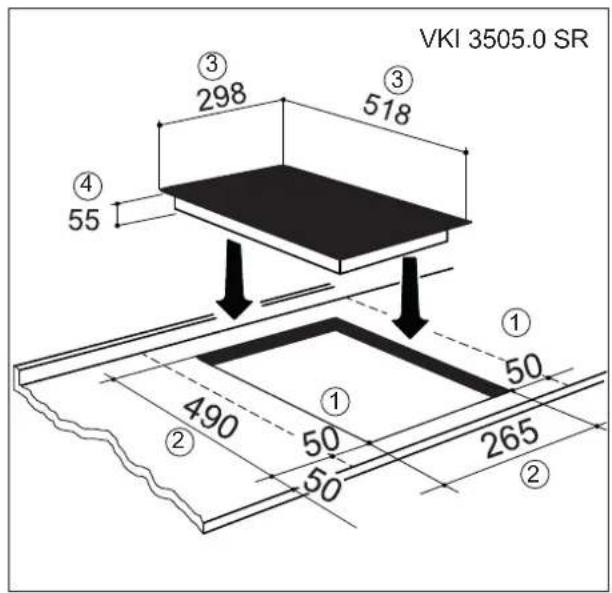
Worktop cut-out
Cut out the worktop recess accurately with a good, straight saw blade or recessing machine. The cut edges should then be sealed so that no moisture can penetrate.
The area is cut out as illustrated. The glass ceramic hob must have a level and flush bearing. Any distortion may lead to fracture of the glass panel. Make sure that the sealing of the hob is properly seated.
text_image
VKI 3505.0 SR ① 50 ② 490 ③ 298 ④ 55 ⑤ 518 ⑥ ⑦ 50 50 265 ②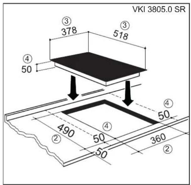
text_image
VKI 3805.0 SR ③ 378 ③ 518 ④ 50 ④ 50 490 ② 50 ② 360
text_image
VKI 3505 + Zub. 1130 443 300 3 140 520 ④ 55 170 418 490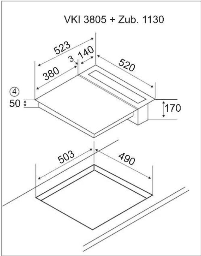
text_image
VKI 3805 + Zub. 1130 523 380 140 520 ④ 50 170 503 490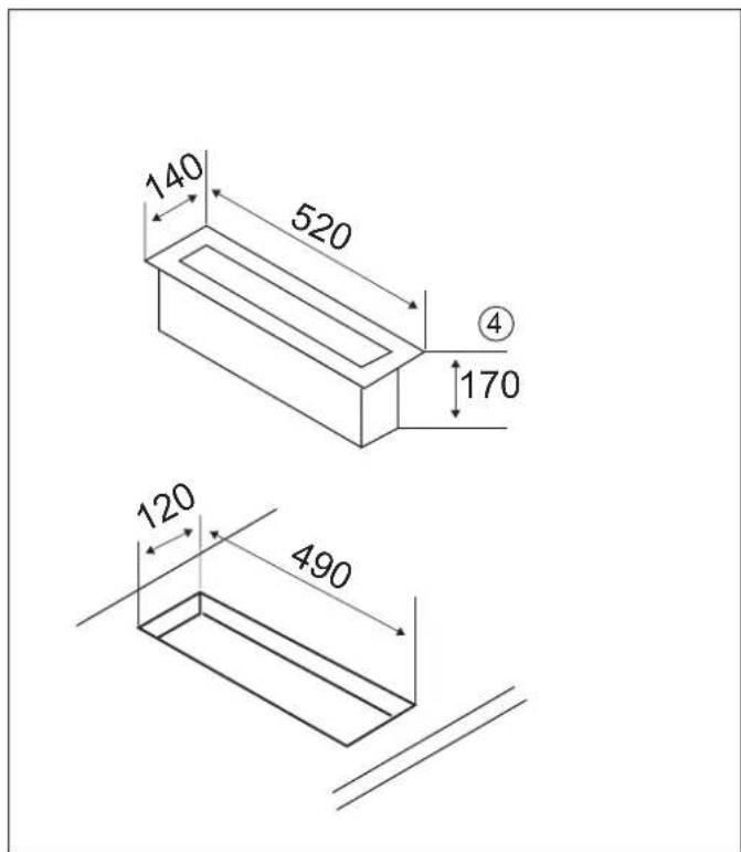
text_image
140 520 ④ 170 120 490Important:
There is a risk of breakage if the hob is canted or subjected to stress during installation!
1 Minimum clearance to adjacent walls
2 Cut-out dimension
3 Outer dimensions of the hob
4 Installation height
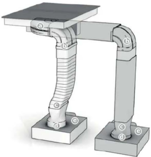
5.3. Extraction air system assembly
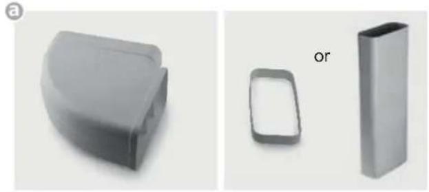
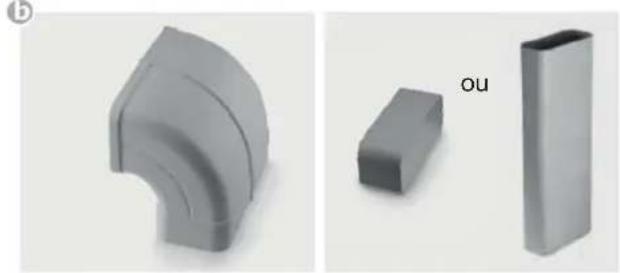
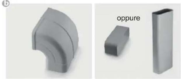
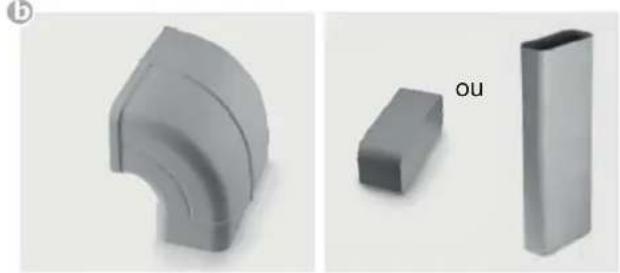
The hob and the fan can be connected with a fl exible hose or a fl at duct.
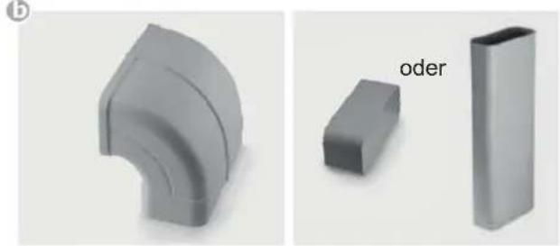
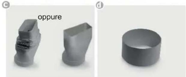
The exhaust air components for on these two options are supplied with the hob and are fitted into each other according to the illustration. Shorten the flat duct with a fine saw if necessary.
natural_image
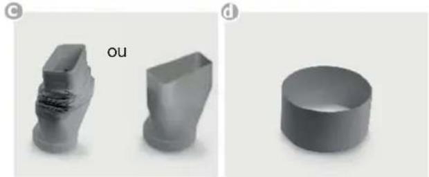
3D diagram of a mechanical assembly with labeled components (a-e), showing two vertical arms and a central threaded component (no text or symbols beyond labels)On point c
The fl exible connection piece is used for a worktop thickness of 600 mm. Please make sure that installation is as taut and crease-free as possible by shortening excess material.
On point f
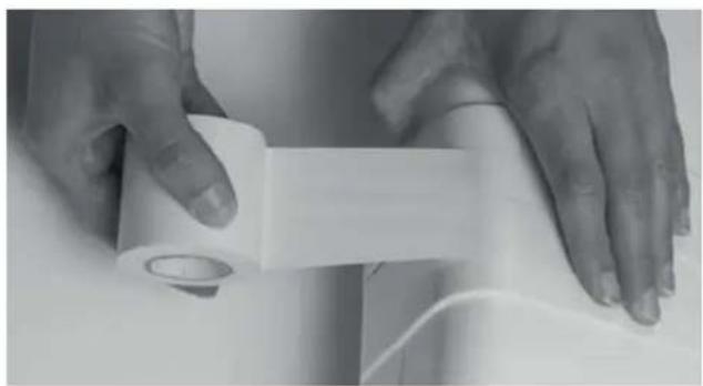
Apply sealing tape to the plinth fan connecting pieces (f) before attaching the adapter piece (d) to the plinth fan (e).
natural_image
Close-up of hands holding a white plastic roller or tape, no visible text or symbolsImportant:
The components must all be firmly fastened as shown with the adhesive tape enclosed after they have been attached.
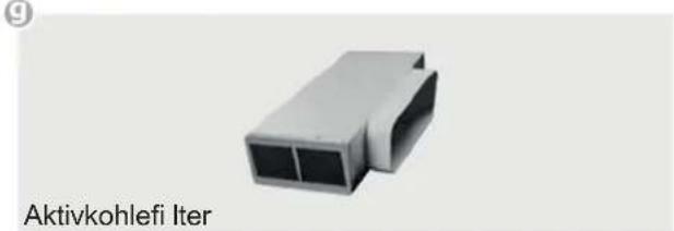
Exhaust air duct components
natural_image
Three 3D-rendered objects: a curved plastic housing, a rounded rectangular prism, and a hollow square (no text or symbols)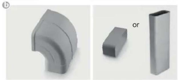
natural_image
Three gray 3D geometric shapes: a curved pipe elbow, a rectangular prism, and a rectangular block, with no text or symbols present.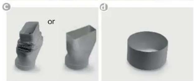
natural_image
Three 3D geometric shapes: a stepped block, a rounded rectangular prism, and a circular ring, all labeled 'or' (no text or symbols on the shapes themselves)
natural_image
Exterior view of a gray electronic device with a black circular component and a black plug, labeled 'Fan' at the bottom (no other text or symbols visible)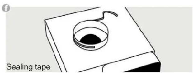
text_image
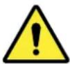
Sealing tapePlinth fi Iter (optional):
natural_image
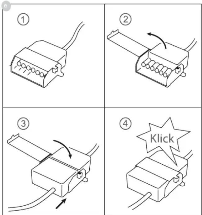
3D model of a gray file interconnect structure (no text or symbols on the object itself)Connect the two 7-pole plus for the fan connection.
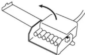
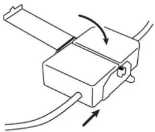
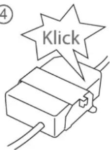
Open the plug retainer on the 7-pole plug (fan) of the hob and attach the 7-pole fan mating connector (e) until it is securely engaged. Then close the plug retainer again.
DANGER
Risk of electric shocks
The fan plug connection must be made before the mains connection!
The appliance must be cut off from the electricity supply before the plug retainer is opened again. The appliance may only be connected to the mains once the plug connection has been made.
The hob may only be switched on when the fan mating connector has been attached and the plug retainer closed.
- The product may only be connected by a qualified fi tter according to applicable local regulations. The same applies for the extraction air connections. The fi tter is responsible for proper functioning at the installation site.
- On installation, observe the relevant national building regulations and the regulations of the electricity suppliers.
- The hob fan can be operated in the extraction air and recirculation air mode.
- Lead the outgoing air outside through a ventilation shaft intended for this purpose or through the wall of the building.
- Outgoing air may not be led into a smoke or exhaust gas fl ue which is in operation. Contact the district master chimney sweep if you are in any doubt.
- A sufficient supply of inlet air must be provided if a wood, coal, gas or oil heater requiring a chimney is operated in the environment of the hob fan, since an insufficient supply of air results in a risk of poisoning. The safe operation of the hob fan is guaranteed when the negative pressure resulting from the hob fan does not exceed 0.04 mbar (4 Pa) and a sufficient supply of inlet air can flow into the room.
- Exhaust air pipes must comply with fire class B 1 DIN 4102.
- Please make sure that the minimum nominal width of the appliance connecting pieces is not reduced.
- A system recommended for the airflow and compatible with the hob extractor should always be used.
- The nominal width of the recirculation air pipe should not be less than 150 mm.
- Exhaust air pipes should be as short as possible. They should not have a 90-degree angle; instead they should have soft bends and no reductions in their cross-section.
- Never use pipes with a diameter of less than 150 mm. No bends/angles may be laid 50 cm before the fan module.
- Always insert a straight piece of approx. 50 cm between two angles/bends.
- The cross-section of wall vents and the cut-out in the base panel should should at least correspond to the exhaust air pipe. The outflow opening must be at least 500~cm^2 . Reduce the height of the skirting boards or make corresponding openings.
- When installing the appliance make sure that the convection air unit is still accessible when the kitchen has been completely installed.
- If necessary levelling feet for the kitchen units must be moved.

PLEASE NOTE
When the convection air mode is in operation, ventilation must be sufficient in order for the air humidity to be removed.
6. Decommissioning and disposal of the appliance
6.1. Switching the appliance off completely
The appliance is to be put out of operation when its useful life has finally come to an end.
- Disconnect the safety fuse for the domestic wiring system in order to prevent a risk of electric shocks.
- Ensure the environmentally friendly disposal of the extractor once it has been removed.
6.2. Disposing of the packaging
Please ensure the environmentally-friendly disposal of the packaging that came with your appliance. Recycling the packaging material saves on resources and cuts down on waste.
6.3. Disposing of old appliances
The symbol on the product or on its packaging indicates that this product may not be treated as household waste. Instead it must be handed over to the applicable collection point for the recycling of electrical and electronic equipment.
By ensuring that this product is disposed of correctly you will help to protect the environment and human health, which could otherwise be harmed through the inappropriate disposal of this product. For more detailed information about recycling this product, please contact your local city office, your household waste disposal service or the shop where you purchased the product.
Table des matières
1 En général 25
natural_image
Pure technical line drawing of a curved structural component with an arrow indicating direction (no text or symbols)natural_image
3D diagram of a mechanical assembly with labeled components (a-e), showing two vertical arms and a central threaded component (no text or symbols beyond labels)Au sujet du point c
natural_image
Close-up of hands holding a white plastic roller with a circular cap, no visible text or symbolsImportant :
natural_image
Three gray 3D-rendered objects: a curved rectangular block, a rounded rectangle with a cutout, and a rectangular prism (no text or symbols)b
natural_image
Three gray 3D geometric shapes: a curved pipe elbow, a rectangular prism, and a rectangular block (no text or symbols)©
natural_image
Three 3D geometric shapes: a stepped block, a rectangular prism, and a circular ring, displayed side by side (no text or symbols)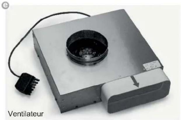
natural_image
Exterior view of a portable electronic device with a circular vent and power plug, labeled 'Ventilateur' (no other text or symbols visible)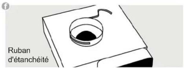
text_image
Glazen afdekkingnatural_image
Pure technical line drawing of a curved structural component with an arrow indicating direction (no text or symbols)natural_image
Technical illustration of a mechanical assembly with labeled components (a-e), showing two vertical supports and a curved internal structure (no text or symbols beyond labels)Betreff ende punt c
natural_image
Close-up of hands holding a white plastic sheet with a circular cap, no visible text or symbolsBelangrijk:
natural_image
Three 3D-rendered mechanical parts: a curved bracket, a rounded rectangular cutout, and a rectangular block with label 'of' (no text or symbols on the shapes themselves)
natural_image
Three 3D geometric shapes: a curved pipe elbow, a rectangular prism, and a rectangular block, all without any text or symbols.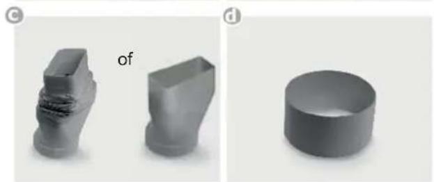
natural_image
Three 3D geometric shapes: a stepped block, a rounded rectangular prism, and a circular ring, all labeled with 'of' in the top-left corner (no other text or symbols)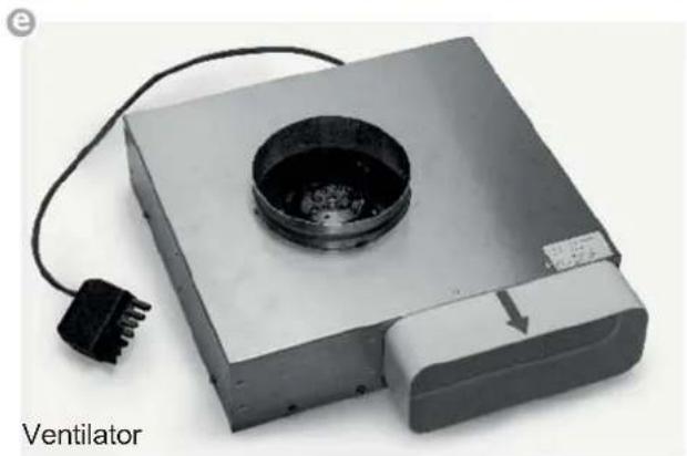
natural_image
Exterior view of a portable electronic device with a circular vent and power plug (no text or symbols visible)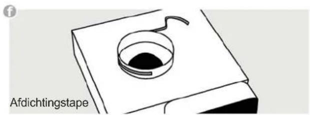
text_image
AfdichtingstapePlintfi Iter (optioneel):
natural_image
Line drawing of a 3-pin electrical connector with leads and wiring (no text or symbols)②
natural_image
Pure mechanical diagram of a device with no text, numbers, or symbols③
natural_image
Pure mechanical diagram showing a lever mechanism with arrows indicating motion (no text or symbols)④
text_image
Klick5.5. Montage kookplaatventilator
text_image
Copertura in vetronatural_image
Diagram of a curved structural component with an arrow indicating direction (no text or symbols)natural_image
Mechanical assembly diagram showing two articulated arms with labeled components (a, b, c, d, e), no text or symbols present.Al punto c
natural_image
Close-up of hands handling a white plastic roller or tape, no visible text or symbolsImportante!
natural_image
Three metallic 3D objects: a curved bracket, a rounded rectangular cutout, and a rectangular prism with a label 'oppure' (no other text or symbols)b
natural_image
Three gray 3D geometric shapes: a curved pipe elbow, a rectangular prism, and a rectangular block labeled 'oppure' (no other text or symbols)©
natural_image
Three 3D geometric shapes: a stepped block, a rectangular prism, and a cylindrical ring, all labeled with 'oppure' in the top-left corner (no other text or symbols)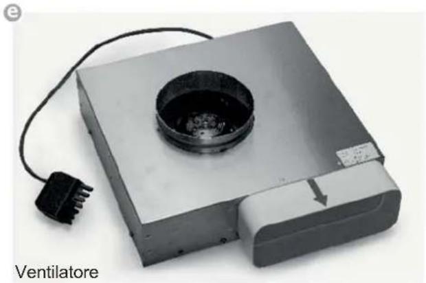
natural_image
Exterior view of a portable electronic device with a circular vent and power plug (no text or symbols visible)
text_image
Nastro ermeticonatural_image
Pure technical line drawing of a curved structural component with an arrow indicating direction (no text or symbols)natural_image
3D diagram of a mechanical assembly with labeled components (a-e), showing two vertical arms and a central threaded component (no text or symbols beyond labels)Al punto c
natural_image
Close-up of hands handling a white plastic roller with a circular cap (no text or symbols visible)Importante:
natural_image
Three 3D model parts: a curved plastic housing, a rounded rectangular prism, and a hollow square (no text or symbols)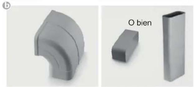
natural_image
Three gray 3D geometric shapes: a curved pipe elbow, a rectangular prism, and a rectangular block labeled 'O bien' (no other text or symbols)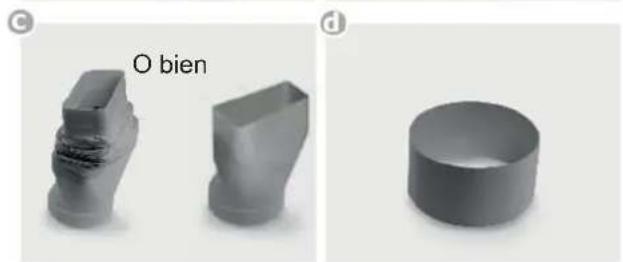
natural_image
Three 3D geometric shapes: a folded block, a rectangular prism, and a circular ring, all labeled with 'O bien' in the top left (no other text or symbols)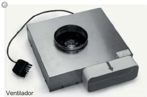
natural_image
Exterior view of a portable electronic device with a circular vent and power plug, labeled 'Ventilador' (no other text or symbols visible)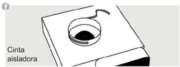
text_image
Cinta aisladoranatural_image
Diagram of a curved structural component with an arrow indicating direction (no text or symbols)natural_image
Mechanical assembly diagram showing two articulated arms with labeled components (a, b, c, d, e), no text or symbols present.Sobre o ponto c
natural_image
Close-up of hands holding a white plastic roller with a circular cap, no visible text or symbolsImportante!
natural_image
Three 3D-rendered metallic objects: a curved bracket, a rounded rectangular cutout, and a rectangular prism (no text or symbols)b
natural_image
Three gray 3D geometric shapes: a curved pipe elbow, a rectangular prism, and a rectangular block (no text or symbols)©

natural_image
Three 3D geometric shapes: a stepped block, a rectangular prism, and a circular ring, displayed side by side (no text or symbols)
natural_image
Exterior view of a portable electronic device with a circular vent and plug, labeled 'Ventilador' (no other text or symbols visible)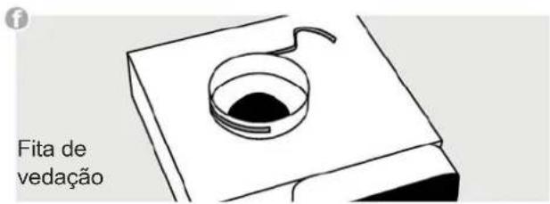
text_image
QR code image containing encoded data, no visible human-readable textK06-180159/01