SET CVB 8501 - Intercom Siedle - Free user manual and instructions
Find the device manual for free SET CVB 8501 Siedle in PDF.

| Product type | Video intercom bus kit |
| Brand | Siedle |
| Model | SET CVB 8501 |
| Power supply for SNG 850- unit | 230 V AC, 50/60 Hz, ±10% |
| SNG output voltage | 27.5 V DC and 12 V AC |
| SNG output current | 0.5 A DC, 1 A AC |
| Camera | 1/3" CMOS sensor, 756 x 504 pixels, 550 TV lines |
| Lens | 3.7 mm |
| Viewing angle | Horizontal approx. 70°, Vertical approx. 50° (estimated) |
| Indoor station screen | 8.8 cm (3.5 inches) color TFT |
| Screen settings | Color and brightness adjustable in 7 levels |
| Volume | Communication and ringtone adjustable in 5 levels |
| Ring tones | 11 tones, call distinction |
| Outdoor station protection rating | IP 54, IK 8 |
| Power supply unit protection rating | IP 30 |
| Operating temperature outdoor station | -20°C to +40°C |
| Operating temperature power supply unit | 0°C to +40°C |
| Number of call buttons outdoor station | 1 or 2 depending on version |
| Main functions | Call, speak, see, open door, LED lighting, heating, ringtone deactivation, floor call |
| Outdoor station mounting | Surface-mounted, recommended height 1.50 m |
| Indoor station mounting | Surface-mounted or plug-in, recommended height 1.60 m |
| Programming | Plug+Play, manual, or via PC with BPS 650- |
| Max. range (0.8 mm wire) | 50 m between SNG and outdoor station, 50 m between SNG and indoor station |
| Electrical installation | To be performed by a specialist, comply with EN 62368-1 |
Frequently Asked Questions - SET CVB 8501 Siedle
User questions about SET CVB 8501 Siedle
0 question about this device. Answer the ones you know or ask your own.
Ask a new question about this device
Download the instructions for your Intercom in PDF format for free! Find your manual SET CVB 8501 - Siedle and take your electronic device back in hand. On this page are published all the documents necessary for the use of your device. SET CVB 8501 by Siedle.
USER MANUAL SET CVB 8501 Siedle
TaK, TbK In-Home-Bus
Kamerazweig
Siedle Basic video set in bus technology with the functions calling, speech, vision and door release. Number of integrated call buttons: 1-2
Each Basic set can be expanded with selected door and indoor stations, and enhanced with switching functions and a telephony connection.
CV 850-...-02 door station performance features:
- Integrated camera with automatic day/night switchover, LED lighting and 2-stage heating
- Integrated door loudspeaker
- Adjustable voice volume
Number of integrated call buttons: 1 (CV 850-1-02), 2 (CV 850-2-02) - Acoustic button acknowledgement can be activated
- Backlit nameplates exchangeable from the front
- For surface mounting with housing front made of high-quality plastic
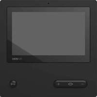
VIB 150-0 indoor station performance features:
- 8.8cm (3.5 inch) TFT colour display
Colour and brightness can be set in seven stages - Speech and call volume can be set in five stages
11 call tones - Call differentiation: Storey call, 2 door calls and internal call from standard/deluxe indoor stations
- LED status display: Incoming calls, active call, muting
- Door release/light function via the bus line
- Manual door connection even without a door call
- Parallel switching of max. 4 indoor stations without internal speech operation
- Handy 2-step mounting: Base plate with terminals can be pre-installed, toolless final assembly
SNG 850-0 set line rectifier performance features:
- 10 bus addresses for supplying the bus users
- Integrated door release and light contact
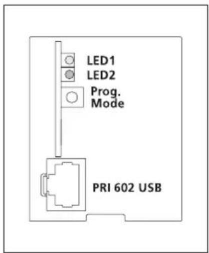
- Programming: manual, Plug+Play or via BPS 650-... (Windows PC) with ZBVG 650-... and PRI 602-... USB
Electrical voltage

- Mounting, installation and servicing work on electrical devices may only be performed by a suitably qualified electrician.
Failure to observe this regulation could result in the risk of serious damage to health or fatal injury due to electric shocks.
Operation at an altitude of up to 2000m above sea level.
- Observe EN 62368-1! In a building installation, an all-pole mains switch with a contact opening of at least 3mm must be provided. The device must not be exposed to water drops or sprayed water! Sufficient ventilation must be ensured. Pay particular attention to ensure that ventilation slots are not covered.
- When using stranded cores as cable material, these must be fitted with wire end ferrules without fail.
Electrostatic charging

As a result of electrostatic charging, direct contact with the circuit board can result in destruction of the device. Direct contact with the circuit board must therefore be avoided.

In the case of video systems, the following mounting situation must be avoided at all costs:
- direct backlight
- direct sunlight
- very bright image backgrounds
- highly reflective walls opposite the camera
- lamps or direct light sources
Scope of supply SET CVB 850-1
CV850-1-02
VIB 150...
- SNG 850-...
- Siedle screwdriver
This product information
Scope of supply SET CVB 850-2
CV850-2-02
- 2 x VIB 150-...
- SNG 850...
- Siedle screwdriver
This product information
Mounting CV 850-...
1 Unscrew the front of the housing. To do this, release the Siedle screw on the underneath of the housing. Hinge the front of the housing forward.
2 Surface mounting the door station. Recommended mounting height appr. 1.50m / 4.9 ft. to centre device. Please note: The cable is inserted in the lower area of the base plate!
3 Strip back the installation cable close to the wall (appr. 10mm ) and insert the cores into the base plate. Fasten the base plate using 4 screws. Close the two openings at the top using rubber stoppers. Install in accordance with the terminal diagram.
The cores may only be laid in the admissible installation space.
4 The pick-up angle of the camera can be mechanically preadjusted on the vertical and horizontal by appr. 30^ depending on the mounting situation. To change the pick-up direction of the camera, it can be
positioned in the required direction. To change the pick-up direction, loosen the two cross-head screws slightly. Position the camera in the required direction. Then fix the required position using the two cross-head screws.
5 Depending on the installation environment, it may be necessary to change the door station speech volume in order to permit clear speech transmission.
6 Hook the front of the housing onto the base plate at the top and close. Tighten the screw on the underneath of the housing.
Mounting SNG 850-...
7 Clip the line rectifier onto the top hat rail.
Mounting VIB 150-...
Strip back cable to appr. 80~mm
8 Recommended mounting height appr. 1.60m to display height/ viewing height.
9 Open the device by pushing in the locking lever and taking off the front side.
10 When mounting directly on the wall, fasten the base plate using 4 screws, paying attention that the plate is the right way up (top marking).
11 When mounting on a switch box, use the screw openings in the centre of the device, paying attention that the plate is the right way up (top marking).
12 Install in accordance with the wiring diagram. The cores of the installation cable must be stored inside the free installation space in the base plate.
13 With Plug+Play programming do not close the housing until programming is under way. Hook the housing into the base plate from above and close by exerting a slight pressure.
Dismantling VIB 150...
14 To remove the housing, press the lock upwards. The circuit board remains in the housing superstructure.
Lettering
15 Open the nameplate from the outside, for example using a flat bladed screwdriver, and carefully remove the inscription insert. To insert the nameplate, lock into place by exerting light pressure.
Installation
16 Connect in accordance with the relevant circuit diagram.
17 Circuit diagram for SET CVB 850-... extended with one Vario door station with BCM 653-...
Note
a) The camera branch and monitor branch must be laid separately and must not be located in the same cable. This can result in disturbance to the picture composition.
Range
The In-Home bus must be installed on one pair of cores when using J-Y(St)Y, and when using a YR conductor, on two YR cores positioned side by side. Using J-Y(St)Y conductors reduces the likelihood of interference.
SNG 850- to door station max. 50m SNG 850- to the most remote indoor device max. 50m with 0.8mm core diameter.
With a core diameter of 0.6mm the range is halved.
Terminal assignment CV 850-...
TaK, TbK In-Home bus camera branch
To, To Relay contact door release
Terminal assignment VIB 150-...
TaM, TbM In-Home bus monitor branch
+M, -M Supply voltage 20-30 V DC
ETb, ERT Storey call button
Terminal assignment SNG 850...
L1, N Power connection
Ta, Tb In-Home bus
b, c Power supply 12 V AC
To, To Relay contact door release
Li, Li Relay contact light
Commissioning
Simple commissioning using Plug+Play programming.
Upgrade capability
The Basic set can be extended with the following components. The overall extension of the Basic sets set must not exceed 10 users, whereby one door station supports two users.
Video indoor station Siedle Basic VIB 150-...
Audio indoor station Siedle Basic AIB 150-...
DoorCom Analog DCA 650-...
- Bus switching unit BSE 650-...
Video door station of the In-Home bus system with BCM 653/658...
- Audio door station of the In-Home bus system
Further system components may be needed.
Plug+Play programming
Basics
Specifications CV 850-...-02
Colour system: PAL
Image pick-up: CMOS sensor 1/3"
756 x 504 Pixel
Resolution: 550 TV lines
Lens: 3,7 mm
Pick-up angle: horizontal appr. 65^ , vertical appr. 50^
Mechanical adjustment range:
30^ horizontal/vertical
Integrated LED lighting
2-step heating: 12 V AC,
max. 110mA
Supply: via In-Home bus
Contact type: contact 24 V, 2 A
Protection system: IP 54, IK 8
Ambient temperature:
-20°C to +40°C
Dimensions (mm) W × H × D:
82× 226× 39
Specifications VIB 150-...
Operating voltage: via In-Home bus
Operating current: on supply via
+M/-M max. 300 mA
Dimensions (mm) W x H x D:
135× 115× 24
Specifications SNG 850-...
Operating voltage: 230 V AC,
+/-10%,50/60 Hz
Operating current: 200mA
Output voltage: 27.5 V DC, 12 V AC
Output current: 0.5 A DC, 1 A AC
Fusing: Primary fuse 1 T 250 mA L,
secondary short circuit proof
Contact type:
2 n.o. contacts 24 V, 2 A
Protection system: IP 30
Ambient temperature:
0^ to +40^
Horizontal pitch (HP): 9
Dimensions (mm) W x H x D:
162× 89× 60
Plug+Play programming offers the simplest opportunity for those without programming experience to commission the set. The entire installation of all users must have been completed.
The housings of the indoor stations must not yet have been closed. The Plug+Play mode must be activated on the SNG 850-... line rectifier. The top call button of the door station is always assigned to the first indoor device.
Conditions for Plug+Play:
- Install the system in accordance with the wiring diagram
- Connect the base plates of the indoor devices, do not yet close the housings
- At the door station, inscribe the assignment of call buttons if possible straight away.
- Set the SNG 850-... to the Plug+Play mode by holding down the programming mode button for 5 seconds. LED 1 must light up continuously.
- Attach the indoor devices to the base plates in the same order as the call buttons are assigned.
- The storey call briefly sounds as an acknowledgement. The next indoor device can be closed.
After all the indoor devices have been closed, press the programming mode button on the SNG 850-...
The programming mode is switched off, the programming of the system is complete.
Reset Plug+Play
In the event of a failed programming attempt, Plug+Play programming can be carried out again.
- Switch off the supply voltage.
- Remove all telephones from the base plates.
- Switch the supply voltage back on again and wait until the SNG 850-... is in normal operating mode (approx. 1-2 minutes)
- Set the SNG 850-... to the
Plug+Play mode by holding down the programming mode button for 5 seconds.
- Hold down the programming button at the door station for 4 seconds until an acknowledgement tone is audible.
- Plug+Play programming can now begin again.
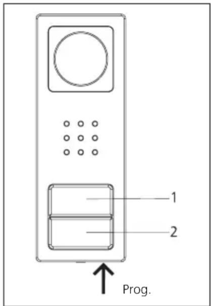
Button assignment
Upper button = Indoor device 1
Lower button = Indoor device 2
Programming - Plug+Play
Procedure - Example
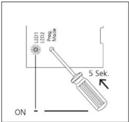
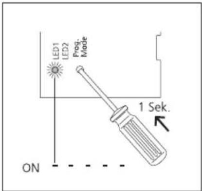
1 Activate the Plug+Play mode at the SNG 850-..., hold down the programming mode button for 5 seconds. LED 1 lights up permanently.
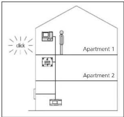
2 Set up the indoor device in residence 1, storey call can be heard as acknowledgement and the LED flashes. Indoor device 1 is assigned to button 1.
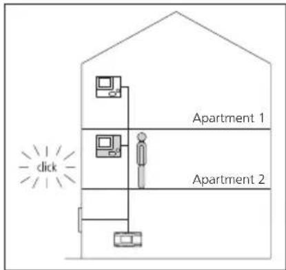
3 Set up the indoor device in residence 2,storey call can be heard and the LED flashes. Indoor device 2 is assigned to button 2.
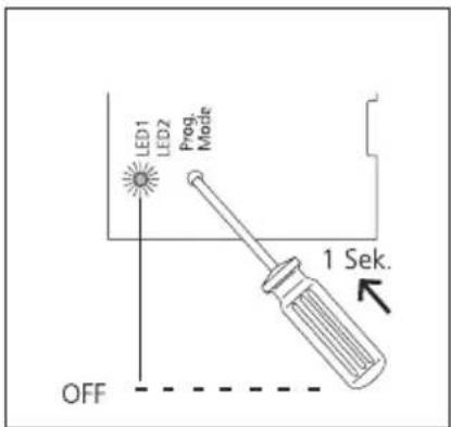
4 Switch off the Plug+Play mode at the SNG 850-... by briefly pressing the programming mode key. LED 1 on the SNG 850-... now flashes again in the normal operating display. All LEDs on the indoor devices are off, the system is ready for operation.
Programming
Overview of functions
Storey call
The storey call button (ERT) is used to call into the apartment from an apartment door. Application e.g. apartment building with 4 apartments and a common staircase. Storey call buttons are installed in front of every apartment front door.
Switching on the light
If you press the door release button twice, the lighting is switched on, provided your electrical installer has connected it.
Muting the bell
If you press the speech button twice, all the ringtones are switched off and back on. To indicate the muting function, the LED display is red. If a visitor rings the doorbell, the button flashes for as long as the indoor device is muted.
Accepting door calls
The call can be accepted by pressing the speech button within 45 seconds after the last ringtone. The call is ended by briefly pressing the speech button again. The indoor telephone only ever transmits speech in one direction and switches over automatically. If the automatic switchover function does not work due to loud incidental noises at the door station, it is possible to force switch over of the speech direction from the indoor device to the door station by pressing and holding down the speech button.
Selecting a door station
Press the speech button to establish a connection to the door station from where the last call came.
Important remarks prior to programming
On principle, the SET CAB/CVB 850... can be commissioned and programmed by one person.
- Complete the installation
- Activate programming mode on the SNG 850... set line rectifier
- Set the door station to the programming mode
- Program the indoor device
End programming mode
While the SNG 850-... is in the programming mode, several steps can be programmed in sequence. There is no need to quit the programming mode after every operation.
| Display LED 1 "Operation" | |||
| LED flashes evenly (System ramp-up) | 0,3s 0,3s | 0,3s 0,3s | 3s |
| LED flashes short on, long off (Operation display, system is functional) | 1s | 20ms 1s | |
| LED flashes short on, long off (Programming mode active) | 0,3s 2s | 0,3s etc. | |
| LED remains alight (Plug+Play programming is active) | |||
| Display LED 2 "Fault" | |||
| LED flashes unevenly (More than 10 users) | 2s | C. | |
| LED flashes unevenly Unsuitable device connected in Plug+Play mode | 0,3s 0,3s 0,2s | s | |
| LED flashes evenly No door station connected in Plug+Play mode | 2s | ||
Programming - manual
Programming door calls
Application
Call from the door station to an indoor device.
The call tone volume can be set on the indoor device (see AIB/VIB 150... operating instructions).
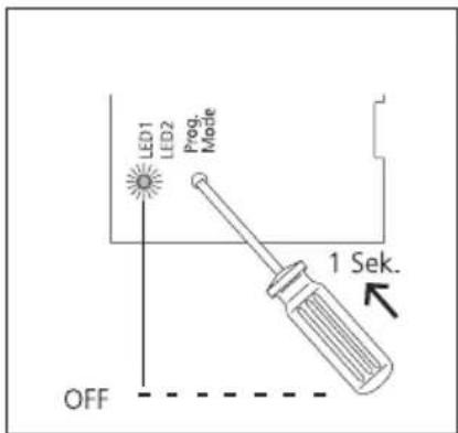
1 Activate the programming mode on the SNG 850-... Briefly press the programming mode button, LED 1 flashes every 2 seconds.
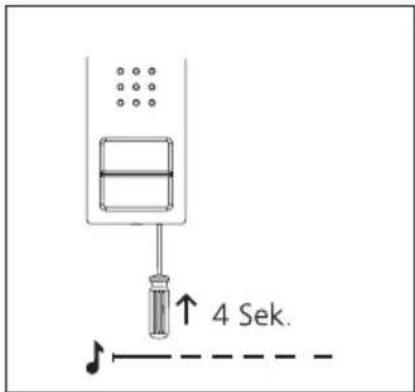
2 At the door station, hold down the programming button for 4 seconds. A protracted acknowledgement tone is then audible which is repeated every 5 seconds as long as the programming mode remains active.
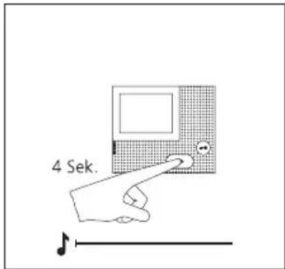
3 Hold down the speech button for 4 seconds. A protracted acknowledgement tone sounds as confirmation and the muting LED begins to flash. The bus indoor device establishes the speech connection to the door station. The bus indoor device is now in the programming mode.
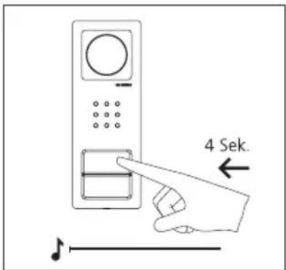
4 On the door station, press and hold the desired call button for 4 seconds until a sustained tone can be heard from the door loudspeaker. The call button is now assigned to the bus indoor device.
5 The call button is now firmly assigned to the bus indoor devices.
Program additional users using the same procedure or quit the programming mode.
Application
TaK, TbK Bus In-Home branch camera
To, To Contact de relais gache
Programming - Plug+play
Fondements
Dimensions (mm) I x H x P :
82× 226× 39
Dimensions (mm) I x H x P :
135× 115× 24
Dimensions (mm) I x H x P :
162× 89× 60
circa 65^ , in verticale circa 50^
TaK, TbK In-Home-Bus cameratak
To, To Relaiscontact deuropener
Klemmenindeling VIB 150...
TaM, TbM In-Home-Bus monitor
+M, -M Verzorgingspanning 20-30 V DC
Programming - plug+play
Forudsaetninger
Tekniske specifikationer CV 850-...02
Farvesystem: PAL
Kamera: CMOS-sensor 1/3"
756 x 504 pixel
TaK, TbK In-Home-buss kameragren
To, To Relakontakt dorroppnare