254301 - Safety harness SILVERLINE - Free user manual and instructions
Find the device manual for free 254301 SILVERLINE in PDF.

| Product Type | Safety Harness |
| Brand | Silverline |
| Model | 254301 |
| Applicable Standards | EN361 (full body harness), EN358 (work positioning) |
| Usage | Fall protection, restraint, work positioning |
| Material | Polyester |
| Maximum Breaking Strength | 16 kN |
| Maximum User Weight | 140 kg (including clothing and tools) |
| Temperature Range | -40 to +80 °C |
| Attachment Points | Dorsal (A) per EN361, lateral (x2) per EN358 |
| Waist Belt Circumference (min/max) | 810 mm / 1200 mm |
| Harness Weight | 1.3 kg |
| Adjustments | Shoulder straps, chest strap, leg straps, waist belt |
| Service Life | 5 years from first use (max 10 years from manufacture) |
| Maintenance | Clean with warm water (30-60°C) with mild neutral pH detergent; air dry; inspect before each use |
| Storage | Dry place, moderate temperature, away from UV and chemicals |
| Repairs | Prohibited; any damaged equipment must be taken out of service |
| Warranty | Lifetime, subject to registration (30 days after purchase) |
Frequently Asked Questions - 254301 SILVERLINE
User questions about 254301 SILVERLINE
0 question about this device. Answer the ones you know or ask your own.
Ask a new question about this device
Download the instructions for your Safety harness in PDF format for free! Find your manual 254301 - SILVERLINE and take your electronic device back in hand. On this page are published all the documents necessary for the use of your device. 254301 by SILVERLINE.
USER MANUAL 254301 SILVERLINE
natural_image
Person wearing a full-body harness and safety harness, full-body view of human torso (no text or symbols visible)
natural_image
Person wearing a full-body safety harness and harness, viewed from behind (no text or symbols visible)


silverlinetools.com
text_image
Anatomical diagram of a human torso with numbered labels pointing to different body parts and harnesses.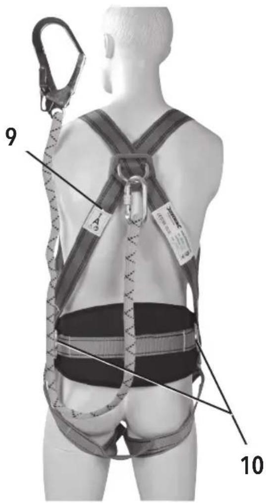
text_image
9 10
natural_image
Person wearing safety harness and hooded jacket, holding a rope (no visible text or symbols)B

natural_image
Person wearing a full-body safety harness and backpack, viewed from behind (no visible text or symbols)C

natural_image
Person wearing a hooded jacket and cap, adjusting a jacket with a belt (no visible text or symbols)D
natural_image
Person wearing a cap and jacket, holding an object with a dark object (no visible text or symbols)E

natural_image
Back view of a person wearing a hooded jacket and full-body harness (no visible text or symbols)F

natural_image
Person wearing a vest and belt, interacting with another person (no visible text or symbols)G

natural_image
Person wearing a belt and pants, hands clasped (no visible text or symbols)H
natural_image
Person wearing a full-body safety harness and belt, hands visible adjusting the belt (no text or symbols)|
English 04 & 48
Français ...... 10 & 56
Deutsch......16 & 62
Español......22 & 68
Italiano 28 & 76
Thank you for purchasing this Silverline tool. This manual contains information necessary for safe and effective operation of this product. This product has unique features and, even if you are familiar with similar products, it is necessary to read this manual carefully to ensure you fully understand the instructions. Ensure all users of the tool read and fully understand this manual.
Description of Symbols
The rating plate on your tool may show symbols. These represent important information about the product or instructions on its use

Wear hearing protection
Wear eye protection
Wear breathing protection
Wear head protection

Read instruction manual

Caution!

Conforms to relevant legislation and safety standards
A Carefully read and understand these instructions and any label attached to the tool before use. Keep these instructions with the product for future reference. Ensure all persons who use this product are fully acquainted with these instructions.
Specification
Model: 254301
Applicable standards:....EN361 (Full Body Harness)
EN358 (Work Positioning Systems)
Purpose:....Fall arrest, restraint & work positioning
Material: Polyester
Maximum strength: 16kN
Temperature range: -40 to +80°C
Attachment points: EN361: Dorsal (A)
EN358: Lateral (x2)
Max. user weight....140kg*
Belt size (min. waist) : 32" (810mm)
Belt size (max. waist): 47" (1200mm)
Net weight: 1.30kg
As part of our ongoing product development, specifications of Silverline products may alter without notice.
*The operator must be able to achieve a safe and comfortable fit, using the adjustment options provided. The Lateral Attachment Points (10) must be located at waist level on the user's sides, opposite each other. The equipment must not be used if it cannot be adjusted to fit the operator comfortably and securely.
Safety Instructions for Height Safety Equipment
⚠ WARNING: Activities involving the use of this equipment are inherently dangerous. ALWAYS carry out a risk assessment before work commences, including rescue arrangements.
⚠ WARNING: Specific training is essential before using this equipment. It must only be used by competent and responsible individuals, taking care not exceeding the limitations of the equipment.
⚠ WARNING: Failure to adhere to any warnings and recommendations given in these instructions may result in severe injury or even death! When using this equipment you personally assume all risks and responsibilities for all damage, injury or death which may occur during or following incorrect use of this equipment. You are responsible for your own actions and decisions.
If you are unable, or not in a position to assume this responsibility or to accept these risks, DO NOT USE THIS EQUIPMENT.
a) NEVER use equipment that has exceeded its shelf and/or service life.
b) This product MUST NOT be stressed beyond its strength rating.
c) DO NOT use components of fall arrest gear outside its limitations, or for applications for which they were not specifically designed.
d) Avoid impacts and rubbing against abrasive surfaces during use, transport and storage.
e) DO NOT use connectors with manual locking mechanisms in areas where they are frequently opened and closed.
f) Ensure locking mechanisms and safety devices engage securely and connectors are fully closed and locked before use.
g) NEVER combine components that are not recommended by the manufacturer as being compatible. One item may interfere with the safe function of another, jeopardising the function of the system as a whole.
h) NEVER attach a fall arrest system to an anchorage if you are unsure about the strength and condition of the anchorage.
i) Take into account the length of every single component of a fall arrest system, including the connectors, when determining the total length of the system.
j) The clearance under the user must be sufficient to prevent him from striking an obstacle in the event of a fall.
k) DO NOT allow any part of a fall arrest, work positioning or restraint system to come into contact with sharp edges or abrasive surfaces during use. Reposition if necessary or choose an alternative anchorage.
1) Any component of a fall arrest system must be individually inspected according to the manufacturer's recommendations and procedures. After assembly, the system must be inspected as a functional unit.
m) Any kind of repair or modification of this equipment is strictly PROHIBITED.
n) DO NOT tie knots in harnesses, lanyards and ropes. DO NOT allow equipment to become tangled.
o) Equipment that has been exposed to extreme conditions, failed an inspection, or has been used to arrest a fall, must be retired and destroyed. Never expose items made with synthetic fibre components to direct flames.
p) DO NOT use shock absorbers that have been partially deployed, or when the plastic sheath is damaged.
q) Destroy retired equipment immediately to prevent further use.
r) All users of fall arrest gear must be medically fit for activities at height and must wear appropriate personal protective equipment for the environment, work carried out, and tools used.
s) Carry out a risk assessment for every activity, and define a rescue plan that can be safely and rapidly executed in case of emergency.
t) All product markings must remain intact and clearly legible for the entire service life of this equipment.
u) Store the equipment with its dedicated service record and usage instructions. Gear with uncertain service history must be removed from service and destroyed.
v) Before using this equipment, ensure that it complies with local federal regulations and other applicable safety standards.
w) Textile products, including webbing and ropes, MUST NOT be marked using ink from marker pens or paint, as these substances may potentially lead to chemical damage of the material.
x) Store in accordance with the manufacturer's instructions.
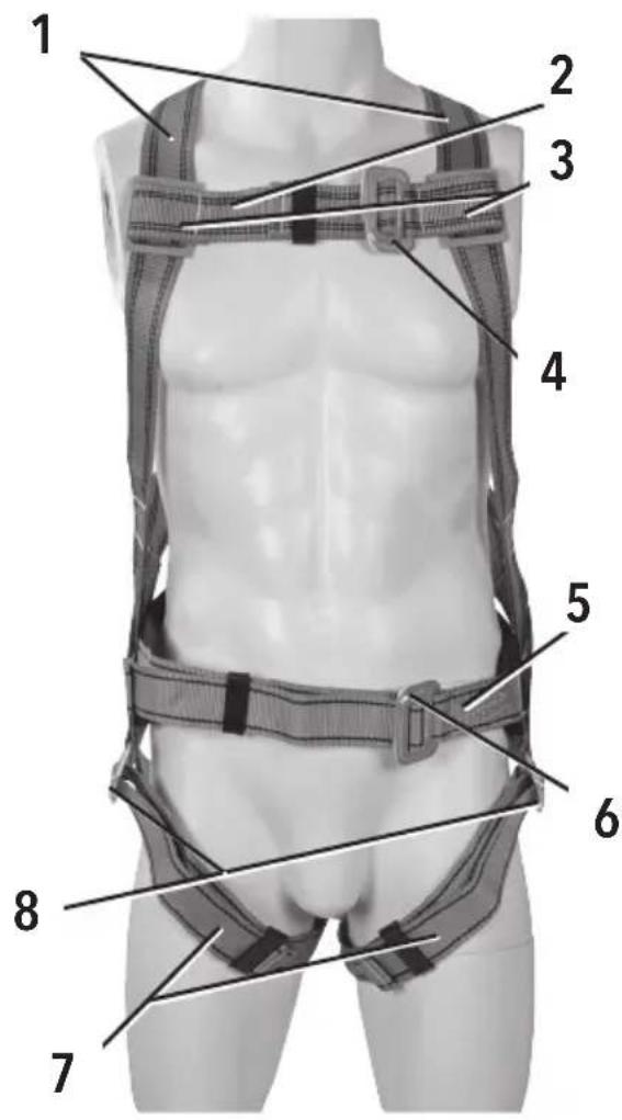
Product Familiarisation
| 1 | Shoulder Straps |
| 2 | Chest Strap |
| 3 | Chest Strap Sliders |
| 4 | Chest Buckle(three-bar slide & square link connections) |
| 5 | Waist Belt Strap |
| 6 | Waist Belt Buckle(three-bar slide & square link connections) |
| 7 | Leg Straps |
| 8 | Leg Strap Buckles(three-bar slide & square link connections) |
| 9 | Dorsal Attachment Point (A) |
| 10 | Lateral Attachment Points (EN358) |
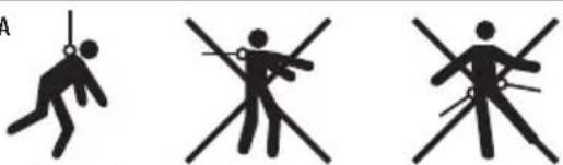
Intended Use
- This harness is designed for use in a fall arrest system, where, used in combination with a suitable lanyard, shock absorber and anchorage, it prevents the user from going into a free fall. It can also be used as part of a restraint/work positioning system, combined with a suitable lanyard.
Fig. A
natural_image
Three pictograms showing different poses of a pole, one with a fulcrum and one without, all without any text or symbols.Fall Arrest Fall Restraint Positioning
Usage limitations
- This equipment is designed for use by one person with a combined total weight no greater than 140kg, including clothing, tools, and other user-borne objects
- Acidic, alkaline, or other environments with harsh substances may damage the equipment. DO NOT expose to corrosive environments for prolonged periods of time. Organic substances and salt water are particularly corrosive to metal parts
- DO NOT use in environments with temperatures lower than -40°C or greater than 80°C
- Avoid contact with rough, abrasive surface, sharp edges, cutting tools etc.
- Equipment must be shielded when used near welding, metal cutting, or other activities that produce large amounts of heat
- Use extreme CAUTION when working near energised electrical sources. Metal hardware conducts electric current. Maintain a safe working distance (at least 3m) from all electrical hazards
- This harness is NOT suitable for applications where the user is going to be suspended for extended periods of time. Use a suspended workseat or a seat sling instead
⚠ WARNING: Fall arrest gear is designed to arrest a fall from height ONLY ONCE! If subjected to an arrested fall, the gear must be withdrawn from service and rendered unusable.
Unpacking Your Product
- Carefully unpack and inspect your product. Fully familiarise yourself with all its features and functions
- Ensure all parts of the product are present and in good condition. If any parts are missing or damaged, have such parts replaced before attempting to use this product
Before Use
Pre-use checks
- A visual and tactile (i.e. by sense of touch) inspection must be carried out before every use. All parts of the gear must be inspected in an area with appropriate light conditions
- Slowly pass webbing, belt or rope through your hands to detect small cuts of 1mm or more in material edges, abrasions and twist damage. Feel for softening and hardening of fibres and look for ingress of contaminants
- Inspect all stitching for visual damage
- Check all hardware and connectors for damage and confirm functionality. Confirm safety devices (such as gates on karabiners etc) are functioning properly
Note: Refer to the 'Maintenance' section for further advice on fault conditions.
Fitting and adjustment
• Preparation (see Fig. B):
- Identify all parts and straps (see 'Product Familiarisation')
- Open and release the Chest Buckle (4) and both Leg Strap Buckles (8)
Note: Loosen all three-bar slide and square link type connections fully, in order to relighten during fitting.
- Lift the harness on the D-ring of the Dorsal Attachment Point (A)(9), and ensure all straps are hanging straight
• Fitting shoulder and chest (see Fig.C-E):
- Fit the Shoulder Straps (1) of the harness over your shoulders
- Place your arms through the Shoulder Straps, so the Dorsal Attachment Point (A)(9) is located on the back
Note: Ensure the harness is not twisted 'inside out', by checking that the D-ring of the Dorsal Attachment Point (A) (9) is located outermost.
-
Close the Chest Strap (2) by inserting the three-bar slide through the square link, so both parts sit flat on top of each other and interlock. Adjust by pulling the end of the webbing through the belt slider, until a snug fit is achieved
-
Adjust the Chest Strap Sliders (3) up or down the harness
Note: The Chest Strap must run squarely over the sternum. It must not run diagonally or close to the throat region.
• Fitting legs (see Fig. F-G):
- Stand upright and straight, locate the Leg Straps (7) and ensure they are not twisted
- Reach behind and pass the first Leg Strap in between your legs from back to front
- Fasten the Leg Strap Buckle (8), by inserting the three-bar slide through the square link, so both parts sit flat on top of each other and interlock
- Repeat on the other side
- Adjust the Leg Straps by pulling the end of the webbing through the belt slider, until a snug fit is achieved and the webbing material sits comfortably, as high as possible, between the inside leg and groin. Release and readjust if necessary, until a safe fit has been achieved
⚠ WARNING: Correct fitting of the Leg Straps (7) is of paramount concern for the safe and effective function of the harness. Severe injury can occur during an arrested fall, if the webbing material is twisted, or if the Leg Straps are not adjusted properly in the groin region.
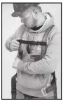
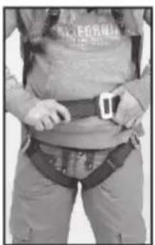
• Fitting waist belt (see Fig. H-I):
-
Stand upright and straight, locate both ends of the Waist Belt Strap (5) and ensure they are not twisted
-
Fasten the Waist Belt Buckle (6), by inserting the three-bar slide through the square link, so both parts sit flat on top of each other and interlock
- Adjust the Waist Belt Strap by pulling the end of the webbing through the belt slider, until a snug fit is achieved
Note: Confirm comfortable yet snug fit of the harness by squatting down and moving your arms above your head. The user must be able to comfortably move around and reach his working position, without the harness restricting movement.
Connecting to other fall arrest system components
- Use the Dorsal Attachment Point (A) (9) to connect to the shock absorber or shock absorber/lanyard combination using a suitable karabiner
WARNING: Karabiners and other connectors must ALWAYS be used with the gate closed and securely locked. Refer to the connector manufacturer's instructions for verification and inspection procedure.
⚠ WARNING: The total length of a lanyard connected to an energy absorber should NOT exceed 2m.
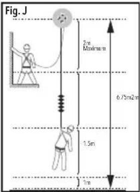
Clearance
- Fall clearance:
Before use, it is essential to verify the clearance required beneath the user. This clearance must be sufficient to prevent the user from hitting the ground or another obstacle, in the event of a fall (see Fig. J)
- Swing falls:
⚠ WARNING: The force of striking an object in a swing fall may cause serious injury or death.
Swing falls occur when the anchorage is not located directly above the point where a fall occurs (see Fig. K). Minimise swing falls by working as close as possible to the anchorage. DO NOT enter a situation where a swing fall could occur, if it is likely to result in an injury
Note: The risk of swing falls significantly increases the clearance required when using a self-retracting lifeline or another variable length connecting system.
Connecting to work positioning or restraint systems
Note: This harness is fitted with a Waist Belt Strap (5) and Lateral Attachment Points (10) that enable its use in work positioning systems as described in EN358.
- The Lateral Attachment Points (10) are designed to either hold the user in a certain position whilst working (work in suspension), or to prevent the worker from entering a zone where a fall is possible (travel restraint, leash principle, see Fig. L)
- The Lateral Attachment Points must ONLY be used to attach to a work positioning system. DO NOT connect to a fall arrest system
• ALWAYS use the two lateral D-rings together by clipping a suitable positioning lanyard between them
• There should be a supporting surface for the feet for comfortable work positioning - Movement must be restricted to a maximum of 0.6m, and the lanyard
text_image
Fig. J 2 m Maximum 6.75m2m 1.5m 1m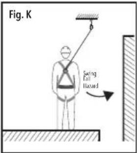
text_image
Fig. K Swing Fall Hazard
text_image
Fig. L Restraint Laryard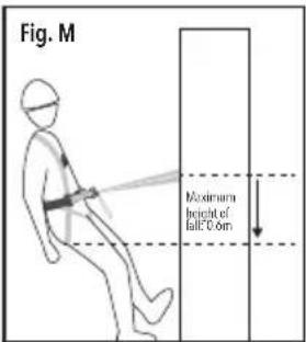
text_image
Fig. M Maximum height of fall 0.05mmust be kept under constant tension (see Fig. M)
⚠ WARNING: When connectors are
poorly positioned, the attachment D-rings could act as a lever on the gate of a karabiner and subsequently damage it, when sudden tension comes on to the rope. ALWAYS ensure that connectors remain safely positioned during use.
Compatibility
- This harness is compatible with miscellaneous fall arrest systems and safety gear, including but not limited to the following Silverline products:
• 253162 Shock Absorbing Lanyard
• 253600 Karabiner
• 252190 Restraint Positioning Lanyard
Notes:
- Connecting hardware must be compatible in size, shape, and strength. Non-compatible connectors may accidentally disengage and lead to serious injury or even death
- Only use connectors, such as D-rings, snaphooks, karabiners and other equipment with a minimum rating of 22kN
⚠ WARNING: Always verify that all components used in combination with each other are compatible.
Anchorage requirements
text_image
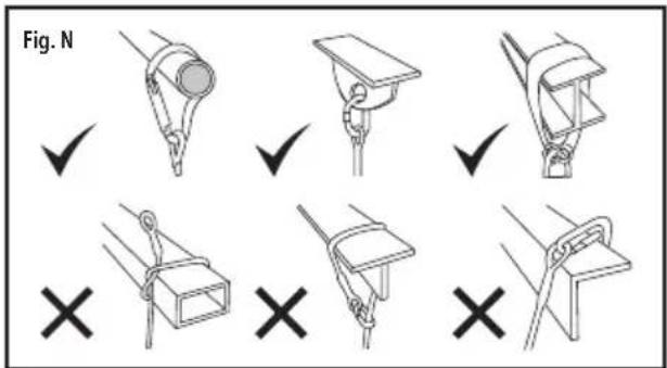
Fig. N ✓ ✓ ✓ ✗ ✗ ✗ ✗- According to EN795 the minimum strength of any anchorage is 10kN
- Check anchorage for signs of deterioration
- As with all fall arrest gear, anchorages must be subjected to regular inspections by a competent person. Inspect at least once every three months and record findings in a dedicated service record
- Check that the karabiner is the correct size for the anchorage to be used. If the karabiner is too small, use an anchor sling to connect to the anchorage
Anchorage position
- The anchorage of the system should preferably be located above the user's position
Use as part of a fall arrest system
- Anchorages selected for fall arrest systems should be capable of sustaining a static load, applied in the directions permitted by the system of at least:
• 22kN for non-certified anchorages, or
- Two times the maximum arrest force for certified anchorages
- If more than one system is attached to one anchorage, the required strength should be multiplied by the number of systems attached
Removing the harness
- Ensure you are located in a safe place away from any fall hazards
- Open both Leg Strap Buckles (6) by passing the three-bar slide through the square link
- Open the Chest Strap (2) buckle
- Remove your arms from the harness
Note: Inspect the harness after use, and follow instructions for cleaning, disinfection, transport and storage as outlined in 'Maintenance'.
Operation
Note: This equipment must ONLY be used by competent operators. All users must be trained in its safe use. Inexperienced users must receive instruction prior to using this equipment. A risk assessment must be carried out before undertaking any operations requiring fall arrest equipment.
⚠ WARNING: ALWAYS wear personal protective equipment appropriate for the work area and type of activity, including but not limited to, eye protection, gloves, hard hat, protective shoes and hearing protection.
Note: Check the correct fitting and adjustment at least every 2 hours during use. This may save your life! Regularly check connections with other equipment in the system, and ensure various system components are correctly positioned with respect to each other.
Rescue plan
⚠ WARNING: A suitable and sufficient risk assessment must be carried out before commencing with any kind of work at height, or any work that requires the use of personal protective equipment (PPE) as a control measure.
- The user must have a rescue plan and the means at hand to implement it
- The plan must take into account the equipment and special training necessary to effectively conduct prompt rescue under all foreseeable conditions
Accessories
- Additional fall arrest gear, workwear and other personal protection equipment is available from your Silverline stockist
Maintenance
Note: All fall arrest equipment must be regularly inspected, cleaned and maintained by a competent person, in accordance with local laws and regulations. Maintenance must be recorded in a dedicated service record (see end of this manual).
⚠ WARNING: Carry out a visual and tactile inspection of all components every time the equipment is used. Carry out a detailed examination if the equipment has not been used for some time. Note: A thorough, detailed examination of the equipment must be carried out at regular intervals, at least once annually, or more frequently depending on use.
⚠ WARNING: It is ILLEGAL to carry out any kind of repair or modification to this equipment.
⚠ WARNING: Should any damage be detected, remove the equipment from service immediately. It must then be rendered unusable and discarded.
Visual/tactile inspection
The following defects potentially result in degradation and/or weakening of equipment components:
- Cuts of 1mm or more at the edges of webbing
- Surface abrasion across the face of the webbing, at webbing loops and around the edges
- Damage to stitching
- Knots other than those intended by the manufacturer
- Chemical attack potentially resulting in local weakening and softening (often indicated by flaking of the surface). Discolouration of the fibres may also be present
- Heat or friction damage indicated by fibres with a glazed appearance which may feel harder than surrounding fibres
- UV-light degradation which can be difficult to identify, particularly visually, but there may be some loss of colour (if dyed) and a powdery surface
- Partially deployed energy absorber (e.g. short pull-out of tear webbing)
- Contamination (e.g. with dirt, grit, sand etc.) which may result in internal or external abrasion
- Damaged, oxidised or deformed fittings (e.g. karabiners, screw link connectors, scaffold hooks)
- Damage to the sheath and internal damage to the core of a rope
Note: See 'Service life and product obsolescence' if such damage or other defects are detected during inspection.
Cleaning
Note: Correct cleaning is essential to ensure integrity of this equipment. Follow the cleaning instructions below without deviation.
- Clean webbing straps and buckles in warm water (30 – 60°C) with a mild pH neutral (pH7) household detergent. In the event of minor soiling, wipe with a cotton cloth or carefully clean using a soft brush
- DO NOT under any circumstances use any abrasive materials, acids, basic detergents or solvents
- Disinfect parts that come into contact with the operator's skin, using a disinfectant suitable for the material of the equipment (see 'Specification'). Strictly follow the disinfectant manufacturer's recommendations and procedures
- ALWAYS allow the equipment to dry naturally, and keep it away from open fire or any other heat source
Note: This also applies to equipment that has become wet during use.
Transport
- ALWAYS transport this equipment inside a dedicated bag or suitable container that protects it from mechanical damage and shields the equipment from high temperatures, humidity, UV rays and chemicals
Storage
- Store this tool carefully in a secure, dry place out of the reach of children
- Store at moderate temperature and humidity, away from direct sunlight or chemicals, inside a dedicated, UV-proof bag or container
- Never place heavy objects on top of this equipment
Disposal
Service life and product obsolescence
WARNING: Fall arrest gear is designed to arrest a fall from height ONLY ONCE! If subjected to an arrested fall, the gear must be withdrawn from service and rendered unusable.
Note: The date on which the product is removed from the original packaging for the first time becomes the 'date of first use', which should be recorded on the Inspection Record (see end of this manual). The specified working life begins from this point.
- Due to the ingress of dirt and grit, chemical contamination, edge and surface damage, UV-light degradation and general wear and tear, all fall arrest, work positioning and restraint equipment manufactured from synthetic fibres (webbing and/or rope) is subject to a manufacturer's statement of obsolescence, which is a requirement of BS EN365:2004
- This equipment is subject to a maximum working life of 5 years from the recorded date of first use, providing the product has been correctly stored, maintained and subjected to regular inspections by a trained and competent person
- New equipment may be stored for a maximum of 5 years from the date of manufacturing as indicated on the product, and will still give the potential 5-year working life – providing it remains in the original manufacturer's packaging
Note: Other reasons why the product may be considered obsolete include, but are not limited to, changes of applicable standard, regulations or legislation, development of new techniques, or incompatibility with other equipment.
⚠ WARNING: Remove fall arrest equipment from service if:
- it has been used to arrest a fall
- any damage is present
- identification is not evident (permanent markings are not legible or have been damaged/removed)
- it exceeds its specified service life
- its full service history is unknown
- you have any doubt as to its integrity
Silverline Tools Guarantee
This Silverline product comes with a forever guarantee
Register this product at www.silverlinetools.com within 30 days of purchase in order to qualify for the forever guarantee. Guarantee period begins according to the date of purchase on your sales receipt.
Registering your purchase
Registration is made at silverlinetools.com by selecting the Guarantee Registration button. You will need to enter:-
- Your personal details
• Details of the product and purchase information
Once this information is entered your guarantee certificate will be created in PDF format for you to print out and keep with your purchase.
Terms & Conditions
Guarantee period becomes effective from the date of retail purchase as detailed on your sales receipt.
PLEASE KEEP YOUR SALES RECEIPT
If this product develops a fault within 30 days of purchase, return it to the stockist where it was purchased, with your receipt, stating details of the fault. You will receive a replacement or refund.
If this product develops a fault after the 30 day period, return it to:
Silverline Tools Service Centre
PO Box 2988
Yeovil
BA21 1WU, UK
The guarantee claim must be submitted during the guarantee period.
You must provide the original sales receipt indicating the purchase date, your name, address and place of purchase before any work can be carried out.
You must provide precise details of the fault requiring correction.
Claims made within the guarantee period will be verified by Silverline Tools to establish if the deficiencies are related to material or manufacturing of the product.
Carriage will not be refunded. Items for return must be in a suitably clean and safe state for repair, and should be packaged carefully to prevent damage or injury during transportation. We may reject unsuitable or unsafe deliveries.
All work will be carried out by Silverline Tools or its authorized repair agents.
The repair or replacement of the product will not extend the period of guarantee
Defects recognised by us as being covered by the guarantee shall be corrected by means of repair of the tool, free of charge (excluding carriage charges) or by replacement with a tool in perfect working order.
Retained tools, or parts, for which a replacement has been issued, will become the property of Silverline Tools.
The repair or replacement of your product under guarantee provides benefits which are additional to and do not affect your statutory rights as a consumer.
What is covered:
The repair of the product, if it can be verified to the satisfaction of Silverline Tools that the deficiencies were due to faulty materials or workmanship within the guarantee period.
If any part is no longer available or out of manufacture, Silverline Tools will replace it with a functional replacement part.
Use of this product in the EU.
What is not covered:
Silverline Tools does not guarantee repairs required as a result of:
Normal wear and tear caused by use in accordance with the operating instructions eg blades, brushes, belts, bulbs, batteries etc.
The replacement of any provided accessories drill bits, blades, sanding sheets, cutting discs and other related items.
Accidental damage, faults caused by negligent use or care, misuse, neglect, careless operation or handling of the product.
Use of the product for anything other than normal domestic purposes.
Change or modification of the product in any way.
Use of parts and accessories which are not genuine Silverline Tools components.
Faulty installation (except installed by Silverline Tools).
Repairs or alterations carried out by parties other than Silverline Tools or its authorized repair agents.
Claims other than the right to correction of faults on the tool named in these guarantee conditions are not covered by the guarantee.
Introduction
natural_image
Three pictograms showing different poses of a stick or rod, with no text or symbols present.text_image
Fig. N ✓ ✓ ✓ ✓ × × ×natural_image
Three pictograms showing different poses of a person holding a tool, with no visible text or symbols.text_image
Abb. J 2m Maximum 6.75m2m 1.5m 1m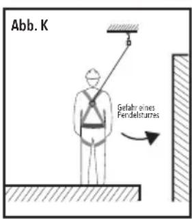
text_image
Abb. N ✓ ✓ ✓ ✓ ✗ ✗ ✗ ✗Silverline Tools Service Centre
PO Box 2988
Yeovil
natural_image
Three pictograms showing different poses of a person holding objects, no text or symbols presenttext_image
Fig. N ✓ ✓ ✓ ✓ ✗ ✗ ✗ ✗Silverline Tools Service Centre
PO Box 2988
Yeovil
BA21 1WU, GB
text_image
Fig. N ✓ ✓ ✓ ✓ ✗ ✗ ✗ ✗⚠ WAARSCHUWING: Vervang valbeveiliging uitrusting wanneer:
Silverline Tools Service Centre
PO Box 2988
Yeovil
BA21 1WU, GB
text_image
Rys. N ✓ ✓ ✓ ✓ × × ×Silverline Tools Service Centre
PO Box 2988
Yeovil
BA21 1WU, UK
Thank you for purchasing this Silverline tool. This manual contains information necessary for safe and effective operation of this product. This product has unique features and, even if you are familiar with similar products, it is necessary to read this manual carefully to ensure you fully understand the instructions. Ensure all users of the tool read and fully understand this manual.
Description of Symbols
The rating plate on your tool may show symbols. These represent important information about the product or instructions on its use

Wear hearing protection Wear eye protection Wear breathing protection Wear head protection

Read instruction manual

Caution!

Conforms to relevant legislation and safety standards
⚠️ Carefully read and understand these instructions and any label attached to the tool before use. Keep these instructions with the product for future reference. Ensure all persons who use this product are fully acquainted with these instructions.
Specification
Model: 252190
Applicable standards:.... EN354 (Fall protection lanyards)
EN358 (Work positioning belts and lanyards) EN362 (Karabiners)
Material: Karabiner: steel grade 35CrMo Scaffold hook: steel grade C45 Rope: Polyester Thimble: Polyethylene
Maximum strength: 25kN
Temperature range: -40 to +80^
Dimensions (total length x rope
diameter x thimble diameter): 1660 x 14mm
Net weight: 0.89kg
As part of our ongoing product development, specifications of Silverline products may alter without notice.
Safety Instructions for Height Safety Equipment
⚠ WARNING: Activities involving the use of this equipment are inherently dangerous. ALWAYS carry out a risk assessment before work commences, including rescue arrangements.
⚠ WARNING: Specific training is essential before using this equipment. It must only be used by competent and responsible individuals, taking care not exceeding the limitations of the equipment.
⚠ WARNING: Failure to adhere to any warnings and recommendations given in these instructions may result in severe injury or even death! When using this equipment you personally assume all risks and responsibilities for all damage, injury or death which may occur during or following incorrect use of this equipment. You are responsible for your own actions and decisions. If you are unable, or not in a position to assume this responsibility or to accept these risks, DO NOT USE THIS EQUIPMENT.
a) NEVER use equipment that has exceeded its shelf and/or service life.
b) This product MUST NOT be stressed beyond its strength rating.
c) DO NOT use components of fall arrest gear outside its limitations, or for applications for which they were not specifically designed.
d) Avoid impacts and rubbing against abrasive surfaces during use, transport and storage.
e) DO NOT use connectors with manual locking mechanisms in areas where they are frequently opened and closed.
f) Ensure locking mechanisms and safety devices engage securely and connectors are fully closed and locked before use.
g) NEVER combine components that are not recommended by the manufacturer as being compatible. One item may interfere with the safe function of another, jeopardising the function of the system as a whole.
h) NEVER attach a fall arrest system to an anchorage if you are unsure about the strength and condition of the anchorage.
i) Take into account the length of every single component of a fall arrest system, including the connectors, when determining the total length of the system.
j) The clearance under the user must be sufficient to prevent him from striking an obstacle in the event of a fall.
k) DO NOT allow any part of a fall arrest, work positioning or restraint system to come into contact with sharp edges or abrasive surfaces during use. Reposition if necessary or choose an alternative anchorage.
1) Any component of a fall arrest system must be individually inspected according to the manufacturer's recommendations and procedures. After assembly, the system must be inspected as a functional unit.
m) Any kind of repair or modification of this equipment is strictly PROHIBITED.
n) DO NOT tie knots in harnesses, lanyards and ropes. DO NOT allow equipment to become tangled.
o) Equipment that has been exposed to extreme conditions, failed an inspection, or has been used to arrest a fall, must be retired and destroyed. Never expose items made with synthetic fibre components to direct flames.
p) DO NOT use shock absorbers that have been partially deployed, or when the plastic sheath is damaged.
q) Destroy retired equipment immediately to prevent further use.
r) All users of fall arrest gear must be medically fit for activities at height and must wear appropriate personal protective equipment for the environment, work carried out, and tools used.
s) Carry out a risk assessment for every activity, and define a rescue plan that can be safely and rapidly executed in case of emergency.
t) All product markings must remain intact and clearly legible for the entire service life of this equipment.
u) Store the equipment with its dedicated service record and usage instructions. Gear with uncertain service history must be removed from service and destroyed.
v) Before using this equipment, ensure that it complies with local federal regulations and other applicable safety standards.
w) Textile products, including webbing and ropes, MUST NOT be marked using ink from marker pens or paint, as these substances may potentially lead to chemical damage of the material.
x) Store in accordance with the manufacturer's instructions.
Product Familiarisation
1 Scaffold Hook
2 Karabiner
3 Rope Thimbles
4 Protective Sleeves (with safety labels)
5 Lanyard
Intended Use
- This lanyard is primarily used to connect to a suitable anchorage as part of a work positioning or restraint system. It can also be used as part of a fall arrest system, if used in combination with a suitable energy absorber.
⚠ WARNING: ALWAYS use in conjunction with a compatible fall arrest system when working at height.
Fig. A
natural_image
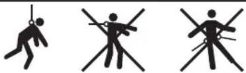
Three pictograms showing human figures in various poses: one with a string, one crossed with a cross, and one crossed with a stick (no text or symbols)Fall Arrest Fall Restraint Positioning
Usage limitations
- This equipment is designed for use by one person with a combined total weight no greater than 140kg, including clothing, tools, and other user-borne objects
- Manual screw locking karabiners should only be used where frequent opening and closing is not required
- Acidic, alkaline, or other environments with harsh substances may damage the hardware of the karabiner. DO NOT expose the karabiner to corrosive environments for prolonged periods of time. Organic substances and salt water are particularly corrosive to metal parts
- DO NOT use in environments with temperatures lower than -40°C or greater than 80°C
- Equipment must be shielded when used near welding, metal cutting, or other activities that produce large amounts of heat
- Use extreme CAUTION when working near energised electrical sources. Metal hardware conducts electric current. Maintain a safe working distance (at least 3m) from all electrical hazards
⚠ WARNING: Fall arrest gear is designed to arrest a fall from height ONLY ONCE! If subjected to an arrested fall, the gear must be withdrawn from service and rendered unusable.
Unpacking your Product
- Carefully unpack and inspect your product. Fully familiarise yourself with all its features and functions
- Ensure all parts of the product are present and in good condition. If any parts are missing or damaged, have such parts replaced before attempting to use this product
Before Use
Pre-use checks
- An inspection must be carried out before every use. All parts of the gear must be inspected in an area with appropriate light conditions
- Check correct function of Karabiner (2) and Scaffold Hook (1), and smooth operation of their safety mechanisms
- Check the Lanyard (5), Rope Thimbles (3) and the Protective Sleeves (4) for damage
Note: Refer to the 'Maintenance' section for further advice on inspection and fault conditions.
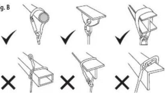
Anchorage requirements
Fig. B
text_image
g. B ✓ ✓ ✓ ✓ ✗ ✗ ✗ ✗- According to EN795 the minimum strength of any anchorage is 10kN
- Check anchorage for signs of deterioration
- As with all fall arrest gear, anchorages must be subjected to regular inspections by a competent person. Inspect at least once every three months and record findings in a dedicated service record
- Check that the karabiner is the correct size for the anchorage to be used. If the karabiner is too small, use an anchor sling to connect to the anchorage
Anchorage position
- The anchorage of the system should preferably be located above the user's position
Use as part of a fall arrest system
- Anchorages selected for fall arrest systems shall be capable of sustaining a static load, applied in the directions permitted by the system of at least
• 22kN for non-certified anchorages, or - Two times the maximum arrest force for certified anchorages
- If more than one system is attached to one anchorage, the required strength shall be multiplied by the number of systems attached
Use as part of a work positioning system
- Structures to which a work positioning system is attached shall be capable of sustaining a static load, applied in the directions permitted by the system of at least 13kN, or twice the potential impact force, whichever is greatest. If more than one system is attached to one anchorage, the required strength shall be multiplied by the number of systems attached
Use as part of a restraint system
- Anchorages to which a restraint or travel restraint system is attached shall be capable of sustaining a static load, applied in the directions permitted by the system of at least
• 4.5kN for non-certified anchorages, or
• Two times the foreseeable force for certified anchorages - If more than one system is attached to one anchorage, the required strength shall be multiplied by the number of systems attached
Connecting to other system components
- When used as part of a fall arrest system, connect to dorsal attachment point of harness, combined with a suitable energy absorber
⚠ WARNING: The total length of a lanyard connected to an energy absorber shall NOT exceed 2m.
- Connect to appropriate D-rings on work positioning or restraint system (refer to manufacturer's recommendations)
⚠ WARNING: Karabiners and other connectors must ALWAYS be used with the gate closed and securely locked.
Clearance
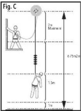
- Fall clearance:
Before use, it is essential to verify the clearance required beneath the user. This clearance must be sufficient to prevent the user from hitting the ground or another obstacle, in the event of a fall (see Fig. C)
- Swing falls:
⚠ WARNING: The force of striking an object in a swing fall may cause serious injury or death.
Swing falls occur when the anchorage is not located directly above the point where a fall occurs (see Fig. D). Minimise swing falls by working as close as possible to the anchorage. DO NOT enter a situation where a swing fall could occur, if it is likely to result in an injury
Note: The risk of swing falls significantly increases the clearance required when using a self-retracting lifeline or another variable length connecting system.
Compatibility
- This product is compatible with miscellaneous fall arrest systems and safety gear, including but not limited to the following Silverline products:
• 251483 Premium Restraint & Fall Arrest Harness
• 251657 Wide Back Support Belt
Notes:
- Connecting hardware must be compatible in size, shape, and strength. Non-compatible connectors may accidentally disengage and lead to serious injury or even death
- Only use connectors, such as D-rings, snaphooks, karabiners and other equipment with a minimum rating of 22kN
- ALWAYS take the length of connectors into consideration, when planning the layout of a fall arrest system, as it will influence the total length of the fall
⚠ WARNING: Always verify that the connecting karabiner and the D-ring on the harness or anchorage connector are compatible.
Operation
Note: This equipment must ONLY be used by competent operators. All users must be trained in its safe use. Inexperienced users must receive instruction prior to using this equipment. A risk assessment must be carried out before undertaking any operations requiring fall arrest equipment.
WARNING: ALWAYS wear personal protective equipment appropriate for the work area and type of activity, including but not limited to eye protection, gloves, hard hat, protective shoes and hearing protection.
Opening and closing the screw gate karabiner
• To open, turn the knurled locking sleeve anticlockwise until the gate opens
- Push the gate inwards to open the karabiner
- To close, release the mechanism, let the gate return to its closed position, and turn the knurled locking sleeve all the way clockwise, into the locked position
WARNING: This karabiner must ALWAYS be used with the gate closed and fully locked. To check whether the gate is securely locked, ensure that the locking sleeve has been turned clockwise all the way, so it prevents the gate from opening when pushed.
text_image
Fig. C 2m Maximum 6.75m2m 1.5m 1m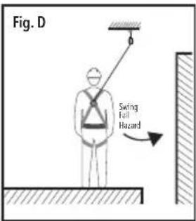
text_image
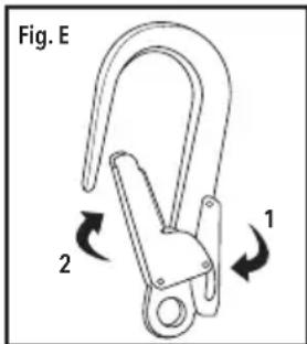
Fig. D Swing Fall HazardOpening and closing the scaffold hook
-
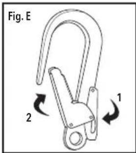
Push the locking lever (see Fig. E: "1") towards the hook's spine
-
The gate (see Fig. E: "2") is now unlocked and can be pushed in to open
-
Release gate and locking lever to close
WARNING: This scaffold hook must ALWAYS be used with the gate closed and fully locked. To check whether the gate is securely locked, try pushing the gate open
text_image
Fig. E 2 1from the outside; it must not open without the locking lever being operated first.
Making connections
(see Fig. B)
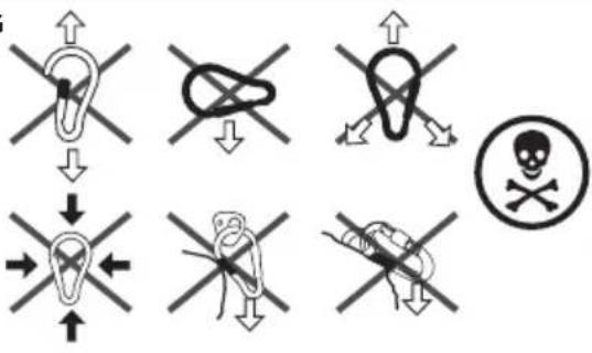
⚠ WARNING: Never apply multiple loads to a single karabiner.
- When using a karabiner to connect to an anchorage, or when connecting components of a fall arrest system together, ensure that accidental disengagement ('rollout') cannot occur
Note: Rollout is possible when interference between a karabiner and the mating connector causes the karabiner's gate or keeper to accidentally open and release.
- DO NOT use connectors that will not completely close over the anchor point
• DO NOT make knots in a lanyard
• DO NOT hook a lanyard back on to itself
• DO NOT attach two or more karabiners to each other
• DO NOT attach two or more karabiners into one D-ring
• DO NOT attach karabiners directly to a horizontal lifeline
⚠ WARNING: ALWAYS follow the manufacturer's instructions supplied with each system component.
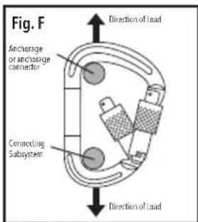
Proper alignment of the karabiner under load
- The karabiner must be installed so that the loads are applied in the area designed for greatest strength (see marking on the product and FIG. F+G)
- The anchorage or anchorage connector should be seated in the radius of the karabiner opposite the gate
• DO NOT apply loads across the gate
- The karabiner must be able to move freely and without interference during use. ANY constraint or external pressure is DANGEROUS
- Be aware that some equipment combinations may reduce the effective strength of the karabiner (e.g. when connecting to wide straps)
text_image
Fig. F Anchorage or anchorage connector Connecting Subsystem Direction of load Direction of loadFig. G
text_image
Safety warning symbols for occupational injuries, including head injury, knee injury, skull, and crossbones with directional arrows and arrows.Note: Regularly check connections with other equipment in the system during use, and ensure various system components are correctly positioned with respect to each other. This may save your life!
Rescue plan
⚠ WARNING: A suitable and sufficient risk assessment must be carried out before commencing with any kind of work at height, or any work that requires
the use of personal protective equipment (PPE) as a control measure.
- The user must have a rescue plan and the means at hand to implement it
- The plan must take into account the equipment and special training necessary to effectively conduct prompt rescue under all foreseeable conditions
Accessories
- Additional fall arrest gear, workwear and other personal protection equipment is available from your Silverline stockist
Maintenance
Note: All fall arrest equipment must be regularly inspected, cleaned and maintained by a competent person, in accordance with local laws and regulations. Maintenance must be recorded in a dedicated service record (see end of this manual).
⚠ WARNING: Carry out a visual and tactile inspection of all components every time the equipment is used. Carry out a detailed examination if the equipment has not been used for some time. Note: A thorough, detailed examination of the equipment must be carried out at regular intervals, at least once annually, or more frequently depending on use.
WARNING: It is ILLEGAL to carry out any kind of repair or modification to this equipment.
⚠ WARNING: Should any damage be detected, remove the equipment from service immediately. It must then be rendered unusable and discarded.
Inspection procedures
- The following procedure helps detect defects potentially resulting in degradation and/or weakening of the Karabiner (2) and Scaffold Hook (1):
- Inspect for missing or altered parts. Refer to the image in 'Product Familiarisation' for identification. Verify each item is present and has not been tampered with
- Inspect the entire karabiner or hook for cracks, nicks or breaks in the metal. Inspect every millimetre
Note: If necessary, clean before inspection, so that even small hairline cracks are visible.
- Inspect for deformation, bent or dented parts. Open the gate and inspect the nose of the karabiner or hook for signs of wear, distortion or damage
- Inspect the metal surface for any signs of corrosion. Steel karabiners and hooks may show red dust as evidence of corrosion; aluminium karabiners may develop pitting or scales
- Inspect for heat damage, which can usually be seen as discolouration or darkening of the metal surfaces
- Perform a functional test: The locking mechanism must function easily, and the karabiner or hook must fully open and close smoothly and easily. When locked, the gate MUST NOT open under pressure from any direction
- Slowly pass the rope through your hands to detect small defects, abrasions and twist damage. Feel for softening and hardening of fibres and look for ingress of contaminants
- The following defects potentially result in degradation and/or weakening of the lanyard:
• Cut/broken fibres or nicks
- Kinks, knots (other than those intended by the manufacturer) or hockling (unravelling due to constant turning of the rope in the same direction, or due to shock loading)
• Brittle, fuzzy or worn fibres, fraying or abrasions
• Overall deterioration or discolouration
• Any kind of modification/attempted repairs
• Hard or shiny spots, fused fibres or strands
- Heat or friction damage indicated by fibres with a glazed appearance which may feel harder than surrounding fibres
• Burnt, charred or melted fibres or strands
• Change in diameter, compared to the original diameter (see 'Specification')
- Rope marked with paint or a permanent marker
- Loose, missing, deformed or damaged Rope Thimbles (3)
-
Eye damage (cuts, nicks, fraying, fusing, abrasion etc.)
-
Damage to protective covers/sleeves/sheaths
- Splices starting to unravel, or showing signs of damage or deterioration
- Partially deployed energy absorber (e.g. short pull-out of tear webbing)
- Damage to stitching
- Chemical attack potentially resulting in local weakening and softening (often indicated by flaking of the surface)
- UV light degradation which can be difficult to identify, particularly visually, but there may be some loss of colour (if dyed) and a powdery surface
- Contamination (e.g. with dirt, grit, sand etc.) which may result in internal or external abrasion
- Damaged, oxidised or deformed fittings (e.g. karabiners, screw link connectors, scaffold hooks)
- Inspect all other components or subsystem of the fall arrest equipment according to manufacturer's instructions
- Record inspection date and results in a dedicated service record (see end of this manual)
Note: Refer to 'Service life and product obsolescence' if any damage or other defects are detected during inspection
Cleaning
Note: Correct cleaning is essential to ensure integrity of this equipment. Follow the cleaning instructions below without deviation.
- Clean the karabiner and hook by wiping it with a soft, lightly oiled cloth
- If this is not sufficient, use warm water with a mild pH neutral (pH 7) detergent, to clean off any foreign matter. Dry thoroughly and lubricate moving parts with a suitable spray lubricant
- Clean lanyard in warm water (30 - 60°C) with a mild pH neutral (pH7) household detergent. In case of minor soiling, wipe with a cotton cloth or carefully clean using a soft brush
- DO NOT under any circumstances use any abrasive materials, acids, basic detergents or solvents
- Disinfect parts that come into contact with the operator's skin, using a disinfectant suitable for the material of the equipment (see 'Specification'). Strictly follow the disinfectant manufacturer's recommendations and procedures
- ALWAYS allow the equipment to dry naturally, and keep it away from open fire or any other heat source
Note: This also applies to equipment that has become wet during use.
Lubrication
- Occasionally apply a small amount of a suitable spray lubricant to the gate mechanism of the karabiner and hook. Afterwards, perform a thorough inspection as described in 'Inspection procedure'
Transport
- ALWAYS transport this equipment inside a dedicated bag or suitable container that protects it from mechanical damage and shields the equipment from high temperatures, humidity, UV rays and chemicals
Storage
- Store this tool carefully in a secure, dry place out of the reach of children
- Store at moderate temperature and humidity, away from direct sunlight or chemicals, inside a dedicated, UV-proof bag or container
- Never place heavy objects on top of this equipment
Disposal
Service life and product obsolescence
⚠ WARNING: Fall arrest equipment is designed to arrest a fall from height ONLY ONCE! If subjected to an arrested fall, the gear must be withdrawn from service and rendered unusable.
Note: The date on which the product is removed from the original packaging for the first time becomes the 'date of first use', which should be recorded on the Inspection Record (see end of this manual). The specified working life begins from this point.
- This equipment is subject to a maximum working life of 5 years from the recorded date of first use, providing the product has been correctly stored, maintained and subjected to regular inspections by a trained and competent person
- New equipment may be stored for a maximum of 5 years from the date of manufacturing as indicated on the product, and will still give the potential 5-year working life – providing it remains in the original manufacturer's packaging
Note: Other reasons why the product may be considered obsolete include, but are not limited to, changes of applicable standard, regulations or legislation, development of new techniques, or incompatibility with other equipment.
⚠ WARNING: Remove fall arrest equipment from service if:
- it has been used to arrest a fall
- any damage is present
- identification is not evident (permanent markings are not legible or have been damaged/removed)
- it exceeds its specified service life
- its full service history is unknown
- you have any doubt as to its integrity
Silverline Tools Guarantee
This Silverline product comes with a forever guarantee
Register this product at www.silverlinetools.com within 30 days of purchase in order to qualify for the forever guarantee. Guarantee period begins according to the date of purchase on your sales receipt.
Registering your purchase
Registration is made at silverlinetools.com by selecting the Guarantee Registration button. You will need to enter:-
- Your personal details
• Details of the product and purchase information
Once this information is entered your guarantee certificate will be created in PDF format for you to print out and keep with your purchase.
Terms & Conditions
Guarantee period becomes effective from the date of retail purchase as detailed on your sales receipt.
PLEASE KEEP YOUR SALES RECEIPT
If this product develops a fault within 30 days of purchase, return it to the stockist where it was purchased, with your receipt, stating details of the fault. You will receive a replacement or refund.
If this product develops a fault after the 30 day period, return it to:
Silverline Tools Service Centre
PO Box 2988
Yeovil
BA21 1WU, UK
The guarantee claim must be submitted during the guarantee period.
You must provide the original sales receipt indicating the purchase date, your name, address and place of purchase before any work can be carried out.
You must provide precise details of the fault requiring correction.
Claims made within the guarantee period will be verified by Silverline Tools to establish if the deficiencies are related to material or manufacturing of the product.
Carriage will not be refunded. Items for return must be in a suitably clean and safe state for repair, and should be packaged carefully to prevent damage or injury during transportation. We may reject unsuitable or unsafe deliveries.
All work will be carried out by Silverline Tools or its authorized repair agents.
The repair or replacement of the product will not extend the period of guarantee
Defects recognised by us as being covered by the guarantee shall be corrected by means of repair of the tool, free of charge (excluding carriage charges) or by replacement with a tool in perfect working order.
Retained tools, or parts, for which a replacement has been issued, will become the property of Silverline Tools.
The repair or replacement of your product under guarantee provides benefits which are additional to and do not affect your statutory rights as a consumer.
What is covered:
The repair of the product, if it can be verified to the satisfaction of Silverline Tools that the deficiencies were due to faulty materials or workmanship within the guarantee period.
If any part is no longer available or out of manufacture, Silverline Tools will replace it with a functional replacement part.
Use of this product in the EU.
What is not covered:
Silverline Tools does not guarantee repairs required as a result of:
Normal wear and tear caused by use in accordance with the operating instructions eg blades, brushes, belts, bulbs, batteries etc.
The replacement of any provided accessories drill bits, blades, sanding sheets, cutting discs and other related items.
Accidental damage, faults caused by negligent use or care, misuse, neglect, careless operation or handling of the product.
Use of the product for anything other than normal domestic purposes.
Change or modification of the product in any way.
Use of parts and accessories which are not genuine Silverline Tools components.
Faulty installation (except installed by Silverline Tools).
Repairs or alterations carried out by parties other than Silverline Tools or its authorized repair agents.
Claims other than the right to correction of faults on the tool named in these guarantee conditions are not covered by the guarantee.
Introduction
The rating plate on your tool may show symbols. These represent important information about the product or instructions on its use

natural_image
Three pictograms showing different poses: one with a stick, one with crossed lines, and one with a cross (no text or symbols)text_image
Fig. G ↑ ↓ → ← → ← → ← → → → → → → → → → → → → → → → → → → → → → → → → → → → → → → → → → → → → → → → → → → → → → → → → → → ←text_image
Fig. G ↑ ↓ ← → ← ← ← ← ← ← ← ← ← ← ← ← ← ← ← ← ← ← ← ← ← ← ← ← ← ← ← ← ← ← ← ← ← ← ← ← ← ← ← ← ← ← ← ← ← ← ← ← ← ← →Silverline Tools Service Centre
PO Box 2988
Yeovil
text_image
Fig. B ✓ ✓ ✓ ✓ ✗ ✗ ✗ ✗text_image
Fig. C 2m b/3m 6.75m/2m 1.5m 1m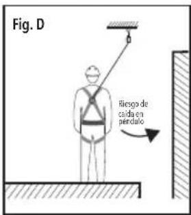
text_image
Safety warning symbols for occupational injuries, including head injury, knee joint injury, skull symbol, and crossbones with directional arrows.natural_image
Three pictograms showing human figures in various poses: one with a stick, one crossed with a cross, and one crossed with a tool (no text or symbols)text_image
g. B ✓ ✓ ✓ ✓ × × ×text_image
Fig. F Anchorage of anchorage connector Connecting Sub-saypoint Direction of Load Direction of Load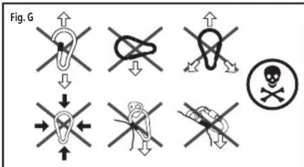
text_image
Fig. GSilverline Tools Service Centre
PO Box 2988
Yeovil
BA21 1WU, GB
text_image
Fig. B ✓ ✓ ✓ ✓ ✗ ✗ ✗ ✗⚠ WAARSCHUWING: De steigerhaak
text_image
Fig. E 2 1text_image
Fig. G ↑ ↓ → ← ← ← ← ← ← ← ← ← ← ← ← ← ← ← ← ← ← ← ← ← ← ← ← ← ← ← ← ← ← ← ← ← ← ← ← ← ← ← ← ← ← ← ← ← ← ← ← ← ← →⚠ WAARSCHUWING: Vervang valbeveiliging uitrusting wanneer:
Silverline Tools Service Centre
PO Box 2988
Yeovil
BA21 1WU, GB
4 Protective Sleeves (with safety labels)
5 Lanyard
Przeznaczenie
text_image
Rys. G ↑ ↓ ← → ← ← ← → → → → → → → → → → → → → → → → → → → → → → → → → → → → → → → → → → → → → → → → → → → → → → → → → → Rys. GSilverline Tools Service Centre
PO Box 2988
Yeovil
BA21 1WU, UK
natural_image
Person wearing a full-body harness and full-body suit with muscular torso (no text or symbols visible)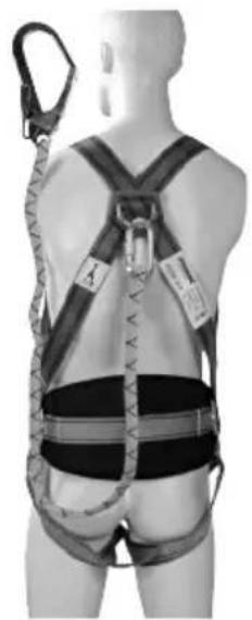
natural_image
Person wearing a full-body safety harness and harness, viewed from behind (no text or symbols visible)GB Guaranteed Forever. Register online within 30 days. Terms and Conditions apply.