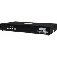
NGIU08C2POE8 - Switch Tripp Lite - Free user manual and instructions
Find the device manual for free NGIU08C2POE8 Tripp Lite in PDF.

| Product Type | Unmanaged Industrial Gigabit PoE+ Ethernet Switch |
| Model | NGI-U08C2POE8 |
| Number of RJ45 Ports | 8 ports 10/100/1000Base-T with PoE+ (30 W per port) |
| Number of SFP Ports | 2 slots 1000Base-X SFP |
| Total PoE Power Budget | 120 W (24 VDC input) / 240 W (48 VDC input) |
| Input Voltage | 24-57 VDC, dual input (primary and redundant) |
| System Power Consumption (without PoE) | 14 W |
| Power Connector | 6-pin terminal block |
| Reverse Polarity Protection | Yes |
| Operating Temperature | -40 °C to 75 °C |
| Storage Temperature | -40 °C to 85 °C |
| Operating Humidity | 5 to 95% RH (non-condensing) |
| Mounting | 35 mm DIN rail (clip pre-installed) |
| Enclosure Material | Rugged metal |
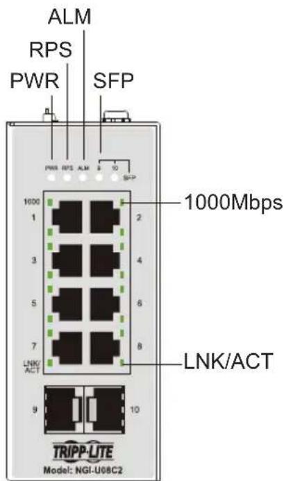
| LED Indicators | PWR, RPS, ALM, PoE 1-8, 1000, LNK/ACT, SFP |
| Configurable DIP Switches | PWR, RPS, Storm Control, QoS, P9/P10 fiber speed |
| Supported Network Standards | IEEE 802.3 10Base-T, 802.3u 100Base-T, 802.3ab 1000Base-T, 802.3af PoE, 802.3at PoE+, 802.1p QoS, 802.3az EEE |
| Advanced Features | Auto-MDI/MDIX, flow control, Storm Control, MAC auto-learning |
| Warranty | 3-year limited |
| Maintenance and Cleaning | Clean with a dry, lint-free cloth. Do not use chemicals or liquids. |
| Safety | Use a SELV power supply (24-57 VDC). Follow electrical codes. Disconnect power before servicing. |
| Spare Parts and Repairability | Replaceable SFP transceivers. No user-serviceable parts inside. |
Frequently Asked Questions - NGIU08C2POE8 Tripp Lite
User questions about NGIU08C2POE8 Tripp Lite
0 question about this device. Answer the ones you know or ask your own.
Ask a new question about this device
Download the instructions for your Switch in PDF format for free! Find your manual NGIU08C2POE8 - Tripp Lite and take your electronic device back in hand. On this page are published all the documents necessary for the use of your device. NGIU08C2POE8 by Tripp Lite.
USER MANUAL NGIU08C2POE8 Tripp Lite
8-Port Unmanaged Plus Industrial Gigabit 10/100/1000 Base-T Ethernet Switch w/ 2 GBE SFP Slots, DIN Mountable
Model: NGI-U08C2
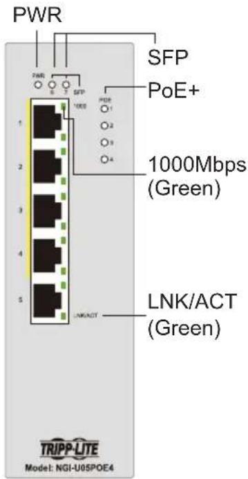
5-Port Unmanaged Plus Industrial Gigabit PoE Ethernet Switch, 4x PoE+ 30W, DIN Mountable
Model: NGI-U05POE4
5-Port Unmanaged Plus Industrial Gigabit PoE Ethernet Switch w/ 2 SFP Ports, 4x PoE+ 30W, DIN Mountable
Model: NGI-U05C2POE4
8-Port Unmanaged Plus Hardened Gigabit PoE Ethernet Switch w/ 2 SFP Ports, 8x PoE+ 30W, DIN Mountable
Model: NGI-U08C2POE8
Español 25 • Français 49 • Русский 73 • Deutsch 97
WARRANTY REGISTRATION
Register your product today and be automatically entered to win an ISOBAR ^® surge protector in our monthly drawing!
tripplite.com/warranty


Manufacturing Excellence.
1111 W. 35th Street, Chicago, IL 60609 USA • tripplite.com/support
Copyright © 2021 Tripp Lite. All rights reserved.
Package Contents
- NGI-U08C2 (non-PoE), NGI-U05POE4, NGI-U05C2POE4 or NGI-U08C2POE8 Plug-and-Play Gigabit PoE Ethernet Switch
• DIN-rail mounting clip (pre-installed on unit) - Owner's Manual
Product Features
- 5 or 8 10/100/1000Mbps RJ45 ports with PoE/PoE+ (NGI-U08C2 is a non-PoE switch)
• Each PoE port provides up to 30W
o Total PoE power budget of 120W (NGI-U05C2POE4 and NGI-U05POE4 models)
Power budget of 240W when input voltage is 48VDC or 120W when input voltage is 24VDC
• 10/100/1000, Full/Half Duplex, Auto MDI/MDIX cross-over function - Plug and Play—no configuration required
- EIP/QoS functionality
- Flow and storm control
• Rugged high-strength metal case - Industrial temperature switch models support operating temperature range of -40^ to 167^ (-40°C to 75°C)
- Easy to read LEDs indicate connection and activity status for each port
Product Features
• Meets the following IEEE standards:
o IEEE 802.3 10Base-T
o IEEE 802.3u 100Base-T
o IEEE 802.3ab 1000Base-T
o IEEE 802.3 Auto Negotiation
o IEEE 802.3z 1000Base-SX/LX
o IEEE 802.1p Class of Service (NGI-U08C2 and NGI-U08C2POE8 Models Only)
o IEEE 802.3az EEE (NGI-U08C2POE8 Only)
o IEEE 802.3af PoE
o IEEE 802.3at PoE+
• Supports MAC address auto-learning and auto-aging
- Pre-installed durable rail clip mounts firmly to any standard 35 mm DIN Rail
- User-configurable DIP switches for alarms (NGI-U08C2POE8 Only)
Optional Accessories
• N001-Series Cat5e 350 MHz Snagless UTP Cables
• N002-Series Cat5e 350 MHz UTP Ethernet Cables
• N200-Series Cat6 Gigabit Molded UTP Ethernet Cables
• N201-Series Cat6 Gigabit Snagless Molded UTP Ethernet Cables
• N320-Series Duplex Multimode 62.5/125 Fiber Patch Cables
• N520-Series Duplex Multimode 50/125 Fiber Patch Cables
• N820-Series Duplex Multimode 50/125 OM3 LSZH Fiber Patch Cables
• N286I-1P25GLXD1 Industrial Gigabit SFP Transceiver, 1000LX 1.25G
• N286I-1P25GSXD Industrial Gigabit SFP Transceiver, 1000SX 1.25G
Product Overview
NGI-U08C2 (non-PoE)


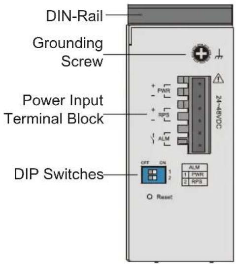
Grounding Screw
Top View
Front View
NGI-U05POE4
Top View
Front View
Product Overview
NGI-U05C2POE4
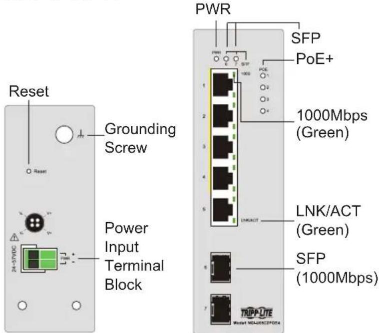
Top View
Front View
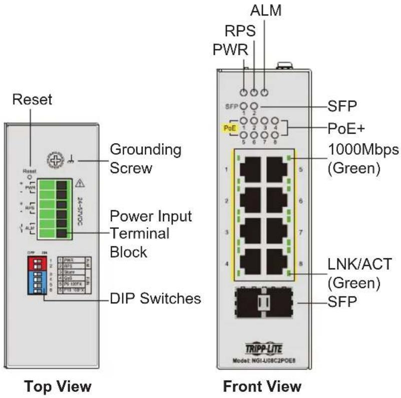
NGI-U08C2POE8
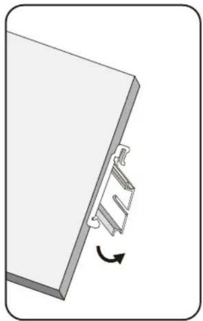
Mounting and Dismounting to DIN-Rail
Mounting the Switch
Place the Gigabit Ethernet PoE+ switches or NGI-U08C2 switch on the DIN rail from above using the slot, then push the front of the switch toward the mounting surface until it snaps into place with a click sound.
Dismounting the Switch
Press the switch from top and pull out the lower edge of the switch, then remove the switch from the DIN rail.
natural_image
Diagram of a mechanical component with a rotating arrow indicating rotation (no text or symbols)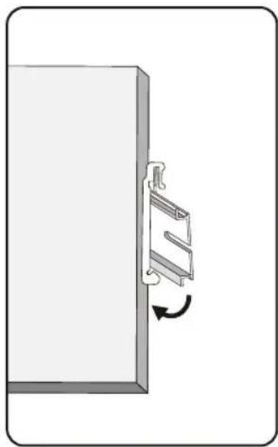
natural_image
Diagram of a door handle with a metal bracket and directional arrow indicating rotation (no text or symbols)Mounting the Switch Removing the Switch

ATTENTION: Use of a corrosion-free mounting rail is advisable. When installing, make sure to allow enough space to properly install the cabling and allow ample airflow.
Mounting and Dismounting to DIN-Rail
Wiring Requirements

WARNING: Safety measures should be taken before connecting the power cable. Turn off the power before connecting modules or wires. The correct power supply voltage is listed on the product label. Check the voltage of your power source to make sure you are using the correct voltage. DO NOT use a voltage greater than what is specified on the product label. Calculate the maximum possible current in each power wire and common wire. Observe all electrical codes dictating the maximum current allowable for each wire size. If current exceeds the maximum rating, the wiring can overheat causing serious damage to your equipment.
Please read and follow these guidelines:
- Use separate paths to route wiring for power and devices. If power wiring and device wiring paths must cross, make sure the wires are perpendicular at the intersection point.
Note: Do not run signal or communications wiring and power wiring through the same wire conduit. To avoid interference, wires with different signal characteristics should be routed separately. - You can use the type of signal transmitted through a wire to determine which wires should be kept separate. A general rule is that wiring that shares similar electrical characteristics can be bundled together.
- Always separate input wiring from output wiring.
- Labelling the wiring to all devices in the system is advised.
Mounting and Dismounting to DIN-Rail
Power Input
Safety measures should be taken before connecting the power cable. Turn off the power before connecting modules or wires. The correct power supply voltage is listed on the product label. Check the voltage of your power source to make sure you are using the correct voltage. DO NOT use a voltage greater than what is specified on the product label. Calculate the maximum possible current in each power wire and common wire. Observe all electrical codes dictating the maximum current allowable for each wire size. If current exceeds the maximum rating, the wiring can overheat causing serious damage to your equipment.

CAUTION: The surface of the power output may be hot, do not touch. Wear protective equipment before making contact.
Wiring Power Input
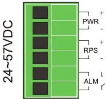
NGI-U08C2 with 6-Pin Terminal Block
Use "PWR" for Primary Power input and "RPS" for Redundant Power input. The top view of Terminal Block is shown in the figure below:
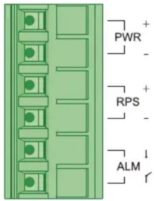
Terminal Block

Caution:
- Use copper conductors only.
- Use wiring cable with rated temperature at least 221°F (105°C).
- Tighten the wire to a torque value 4.5 lb·in (0.5 N·m).
- The wire gauge for the terminal block should range between 12\~24 AWG (4\~0.25 mm2).
To insert the power wire and connect the 24\~48VDC at a maximum of 0.4A DC power to the power terminal block:
- Use a flathead screwdriver to loosen the wire clamp screws.
- Insert the negative/positive DC wires into the PWR-/PWR+ terminals, respectively.
- Tighten the wire-clamp screws to prevent the wires from loosening.

ATTENTION: Use a power supply rated for 24\~48VDC. The device power must be supplied by SELV circuit.
Wiring Power Input
Wiring the Relay Contact (ALM)
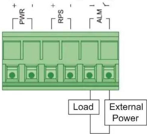
Relay rating: 24V, 1A
The NGI-U08C2 has one set of relay alarm output. This relay contact uses two contacts of the terminal block on the top panel. The two contacts of the 6-pin terminal block connector are used to detect user-configured events. The two wires attached to the fault contacts form an open circuit when a user-configured event is triggered. If a user-configured event does not occur, the fault circuit remains closed.
DIP Switch Settings
The switch supports an Alarm Relay Output function where you can connect an alarm light or a buzzer. When events occur enabled by the DIPs, the switch will operate the relay ON to enable the alarm light or buzzer. The load can be an alarm light, a buzzer or other equipment.
Wiring Power Input
User-Configurable Switches
PWR or RPS "DIP ON": When there is a power loss, the switch will operate as "Relay ON". If connecting only to single power source and a power loss occurs, the switch system will shut down and not operate as "Relay ON".
Port 1\~ Port X: "DIP ON": If the port link is down, the switch will operate as "Relay ON". In doing so, it can help to inform when link-down events occur.
It is not required to connect alarm equipment to the Alarm Relay output port. An ALARM LED indicator is located on the front panel.
Default settings for the DIP switch are set to OFF positions.
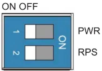
| DIP Position Description | ||
| PWR | ON | Primary power alarm reporting is enabled. |
| OFF | Primary power alarm reporting is disabled. | |
| RPS | ON | Redundant power alarm reporting is enabled. |
| OFF | Redundant power alarm reporting is disabled. | |
Wiring Power Input
Redundant Power Input (NGI-U08C2POE8 Only)
Use "PWR" for Primary Power input and "RPS" for Redundant Power input.
To insert the power wire and connect the +24\~57VDC power to the power terminal block:
- Use a flathead screwdriver to loosen the wire clamp screws.
- Insert the corresponding wires into the contacts.
- Tighten the wire clamp screws to prevent the wires from loosening.
Top View of the Terminal Block
Wiring Power Input
DIP Switch Settings and Reset Button
| DIP Position Description | ||
| PWR | ON | Primary power alarm reporting is enabled. |
| OFF | Primary power alarm reporting is disabled. | |
| RPS | ON | Redundant power alarm reporting is enabled. |
| OFF | Redundant power alarm reporting is disabled. | |
| Storm | ON | Broadcast/DLF storm control is enabled. |
| OFF | Broadcast/DLF storm control is disabled. | |
| QoS | ON | Port-based QoS enabled on P1 & P2. |
| OFF | 802.1p QoS enabled (default). | |
| P9 100FX | ON | Port 9 link speed is set to 100Base-FX. |
| OFF | Port 9 link speed is set to 1000Base-SX/LX. | |
| P10 100FX | ON | Port 10 link speed is set to 100Base-FX. |
| OFF | Port 10 link speed is set to 1000Base-SX/LX. | |
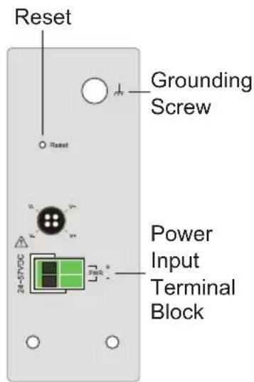
Reset Button: Press the button for a hardware reset (initialization).
Refer to "Top View of the Terminal Block" diagram for button location.
Note: The reset button function is only for hardware reset, it does not affect any setting because the switch model does not require software.
Wiring Power Input
The first two relate to alarm design:
- PWR/RPS
The switch supports dual power input, we define these power source as Primary Power Supplier (PWR) and Redundant Power Supplier (RPS). These two DIP switches are designed to provide an alarm mechanical to monitor the power connective status. If DIP switch is set to ON means alarm function is enabled.
The remaining four relate to functionality:
- Storm
Storm control is used to prevent the local area network (LAN) from being disrupted by broadcast or destination lookup failure (DLF) storm. The storm occurs when broadcast or DLF packets are generated and flood into the LAN, this excessive traffic degrades network performance. If the DP switch is set to ON, it means system will measure broadcast and DLF packets and suppress them if the threshold is reached.
• QoS
The switch supports two types of QoS, Port-based QoS (Port Priority) and VLAN Tag-based QoS (802.1p). Port priority is only enabled on port 1 and port 2 which ingress packets will be handle with high transmission priority. If VLAN packets with pre-defined priority are coming into switch (any port), system will refer to it's specified priority for transmission.
- Fiber Speed – P9 and P10
For legacy operation, there is a dual-speed support (100BASE-FX / 1000BASE-SX/LX) on switch fiber ports. Depending on the network environment, a user can choose the proper SFP transceiver and set the related DIP switch for fiber connectivity.
Wiring Power Input
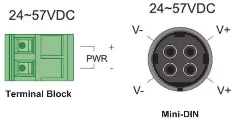
Wiring Power Input (NGI-U05C2POE4 and NGI-U05POE4 Models Only)
You can use "PWR" from the terminal block or 4-pin Mini-DIN for Power input.
Top view of connectors are shown below:

Caution:
• Use copper conductors only.
- Use wiring cable with rated temperature at least 221°F (105°C).
- Tighten the wire to a torque value 4.5 lb·in (0.5 N·m).
- The wire gauge for the terminal block should range between 12\~18 AWG (4\~0.75 mm2).
Connecting to Terminal Block
To insert the power wire and connect the +24\~57VDC at a maximum of 6A DC power to the power terminal block:
- Use a flathead screwdriver to loosen the wire clamp screws.
- Insert the negative/positive DC wires into the PWR-/PWR+ terminals, respectively.
- Tighten the wire clamp screws to prevent the wires from loosening.
Wiring Power Input
Connecting to the 4-Pin Mini DIN Connector
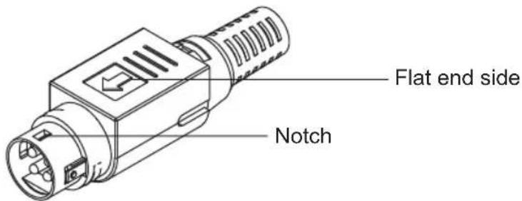
- Face the flat end to the right side of the switch and insert into the female 4-pin receiver.
Note: Make sure the notch is securely inserted properly into female receiver.
- While removing, pull the connector upwards to release the lock and take it out.

ATTENTION: Use a power supply rated for 24\~48VDC. The device power must be supplied by SELV circuit.
RJ45 Cabling
Connect one end of an Ethernet/RJ45 cable into the Ethernet port of the switch and the other end to the attached networking device.
- Ports 1-4 of the switch support Fast Ethernet in addition to Gigabit Ethernet 10/100/1000Base-T PSE Ports (NGI-U05POE4/NGI-U05C2POE4 models only).
- Ports 1-8 of the switch support Fast Ethernet in addition to Gigabit Ethernet 10/100/1000Base-T (NGI-U08C2/POE models only).
- Port 5 of the switch supports Fast Ethernet in addition Gigabit Ethernet 10/100/1000Base-T RJ45 Port (NGI-U05POE4/NGI-U05C2POE4 models only).
- Ports 6-7 of the NGI-U05C2POE4 support only Gigabit speed SFP Slots.
- All RJ45 ports on the Gigabit Ethernet PoE+ and non-PoE switches support Auto Negotiation and Auto MDI/MDI-X to eliminate the need for crossover cabling.
Note: Category 5e cable, Cat6 or above should be used.
Wiring Power Input
Grounding the NGI-Series Switches
Grounding and wire routing help to limit the effects of noise due to electromagnetic interference (EMI). Run the ground connection from the ground screw to the grounding surface prior to connecting devices.

ATTENTION: This product is intended to be mounted to a well-grounded mounting surface (such as a metal panel).
LED Indicators
NGI-U08C2 (Non-PoE)
| LED (Color) Status | Description | |
| PWR (Green) | Illuminated | Primary power is supplied to the switch. |
| Off Primary power off or failure. | ||
| RPS (Green) | Illuminated | Redundant power is supplied to the switch. |
| Off Redundant power off or failure. | ||
| ALM (Red) | Illuminated | External signal device will be activated through the terminal block ALM when there is any alarm.Alarm for following conditions:Power lost (primary or secondary).Abnormal voltage input. |
| Off No alarm to report. | ||
| SFP 9~10 (Green) | Illuminated SFP port link-up. | |
| Blinking | Activity (receiving or transmitting data). | |
| Off Port disconnected or link failed. | ||
| 1000 (Green) | Illuminated | Port is operating in 1000Mbps speed. |
| Off | Port is operating in 10/100Mbps speed. | |
| LNK/ACT (Green) | Illuminated Ethernet link up. | |
| Blinking | Activity (receiving or transmitting data). | |
| Off Port disconnected or link failed. | ||
LED Indicators
NGI-U05C2POE4 and NGI-U05POE4
| LED (Color) Status | Description | |
| PWR (Green) | Illuminated | Power On by terminal block PWR or 4-pin mini DIN connector. |
| Off | Terminal block PWR/4-pin mini DIN connector is not available. | |
| POE 1-4 (Green) | Illuminated Supplying power to PD devices. | |
| Off | No power supplied to PD devices. | |
| 1000 (Mbps) | Illuminated | Copper ports communicate at 1000Mbps speed. |
| Off | Copper ports communicate at 10/100Mbps speed. | |
| LNK/ACT (Green) | Illuminated Ethernet link is up. | |
| Blinking | Activity (receiving or transmitting data). | |
| Off Port disconnected or link failed. | ||
| SFP NGI-U05C2POE4 (Green) | Illuminated Data is transmitting / receiving. | |
| Off Port disconnected or link failed. | ||
LED Indicators
NGI-U08C2POE8
| LED (Color) Status | Description | |
| PWR (Green) | Illuminated Primary Power is connected. | |
| Off | Primary Power failure or not available. | |
| RPS (Green) | Illuminated Redundant Power is connected. | |
| Off | Redundant Power failure or not available. | |
| ALM (Red) | Illuminated | Alarm for no Primary power or Low I/P voltage. |
| Off | No alarm to report or DIP function is disabled. | |
| PoE 1-8 Ports (Green) | Illuminated | PoE power is delivered to the powered device (PD). |
| Off | PoE power feeding is not functioning. | |
| 1000 (Green) | Illuminated Link on 1000Mbps. | |
| Off Link on 100Mbps or 10Mbps. | ||
| LNK/ACT (Green) | Illuminated Ethernet link is up. | |
| Blinking | Activity (receiving or transmitting data). | |
| Off Port disconnected or link failed. | ||
| SFP (Green) | Illuminated Data is transmitting / receiving. | |
| Off Port disconnected or link failed. | ||
Specifications
| Model | NGI-U08C2(Non-PoE) NGI-U05C2 | POE4 NGI-U05POE4 NGI-U08C2POE8 | ||
| Power | ||||
| Input Voltage | Dual power inputs24~48VDC/0.4A | Single power input24~57VDC/6A | Single power input24~57VDC/6A | Dual power inputs24~57VDC/6A |
| Connection 6-pin terminal block 2-pin terminal block 2-pin terminal block | 6-pin terminal block | |||
| Reverse Polarity Protection | Present Present Present | Present | ||
| Power Consumption (System Only) | 11W 14W 13W 14W | |||
| Grounding Screw Present Present Present | ||||
| PoE (Per Port) No 30W | 30W 30W | |||
| PoE Power Budget No | 120W 120W | 120W@24VDC240W@48VDC | ||
| Interface | ||||
| RJ45 | 8 x10/1001000Base-T copper ports support Auto-Negotiation, Auto MDI/MDI-X, Full/ Half Duplex and Flow Control. | 4 x10/1001000Base-T PoE+, 1 x10/1001000Base-T copper ports support Auto-Negotiation, Auto MDI/MDI-X, Full/ Half Duplex and Flow Control.Four copper ports support PoE/PoE+. | 4 x10/1001000Base-T PoE+, 1 x10/1001000Base-T copper ports support Auto-Negotiation, Auto MDI/MDI-X, Full/ Half Duplex and Flow Control.Four copper ports support PoE/PoE+. | 8 x10/1001000Base-T PoE+ copper ports support Auto-Negotiation, Auto MDI/MDI-X, Full/ Half Duplex and Flow Control.Eight copper ports support PoE/PoE+. |
| Fiber Ports | 2x 1000Base-X SFP slots | 2x 1000Base-X SFP slots | - | 2x 1000Base-X SFP slots |
| LED Indicators | PWR (Green): Power by terminal block PWR RPS (Green): Power by terminal block RPS ALM (Red): PWR and RPS failsSFP 9~10 (Green): Port 9~10 SFP link-up 1000 (Green): Port 1~8 Ethernet speed 1000MbpsLNK/ACT (Green): Data Transmitting/Receiving | PWR (Green): Power PoE 1~4 (Green): Supplying power to PD deviceSFP 6~7 (Green): Port 6~7 SFP link-up 1000 (Green): Port 1~5 Ethernet speed 1000MbpsLNK/ACT (Green): Data Transmitting/Receiving | PWR (Green): Power PoE 1~4 (Green): Supplying power to PD device1000 (Green): Port 1~5 Ethernet speed 1000MbpsLNK/ACT (Green): Data Transmitting/Receiving | PWR (Green): Power by terminal block PWR RPS(Green): Power by terminal block RPS ALM (Red): PWR and RPS failsPoE 1~8 (Green): Supplying power to PD device1000 (Green): Port 1~8 Ethernet speed 1000MbpsSFP 9~10 (Green): Port 9~10 SFP link-upLNK/ACT (Green): Data Transmitting/Receiving |
| Alarm Relay Output | 1 alarm relay output for power loss | - | - | 1 alarm relay output for power loss |
Specifications
| Model | NGI-U08C2(Non-PoE) NGI-U05C2 | POE4 NGI-U05POE4 NGI-U08C2POE8 | ||
| Environmental | ||||
| Operating Temperature | -40°F~167°F(-40°C~75°C) | 14°F~140°F(-10°C~60°C) | 14°F~140°F(-10°C~60°C) | -40°F~167°F(-40°C~75°C) |
| Storage Temperature | -40°F~185°F(-40°C~85°C) | -40°F~185°F(-40°C~85°C) | -40°F~185°F(-40°C~85°C) | -40°F~185°F(-40°C~85°C) |
| Operating Humidity | 5 to 95% RH(non-condensing) | 5 to 95% RH(non-condensing) | 5 to 95% RH(non-condensing) | 5 to 95% RH(non-condensing) |
| Storage Humidity | 5 to 95% RH(non-condensing) | 5 to 95% RH(non-condensing) | 5 to 95% RH(non-condensing) | 5 to 95% RH(non-condensing) |
| Operating Altitude 6561 | ft. (2000 m) 6561 ft. (2000 m) 6561 ft. (2000 m) | |||
| Regulatory Approvals | ||||
| EMI/EMC | FCC Part 15EN 55011EN 61000-6-4EN 61000-6-2EN 55032EN 55024 | FCC Part 15EN 55011EN 61000-6-4EN 61000-6-2EN 55032EN 55024 | FCC Part 15EN 55011EN 61000-6-4EN 61000-6-2EN 55032EN 5502 | FCC Part 15EN 55011EN 61000-6-4EN 61000-6-2EN 55032EN 55024 |
ATTENTION: If the switch is used in a manner not specified here, the protection provided by the switch may be impaired.
Warranty and Product Registration
3-Year Limited Warranty
Seller warrants this product, if used in accordance with all applicable instructions, to be free from original defects in material and workmanship for a period of three (3) years from the date of initial purchase. If the product should prove defective in material or workmanship within that period, Seller will repair or replace the product, at its sole discretion.
THIS WARRANTY DOES NOT APPLY TO NORMAL WEAR OR TO DAMAGE RESULTING FROM ACCIDENT, MISUSE, ABUSE OR NEGLECT. SELLER MAKES NO EXPRESS WARRANTIES OTHER THAN THE WARRANTY EXPRESSLY SET FORTH HEREIN. EXCEPT TO THE EXTENT PROHIBITED BY APPLICABLE LAW, ALL IMPLIED WARRANTIES, INCLUDING ALL WARRANTIES OF MERCHANTABILITY OR FITNESS, ARE LIMITED IN DURATION TO THE WARRANTY PERIOD SET FORTH ABOVE; AND THIS WARRANTY EXPRESSLY EXCLUDES ALL INCIDENTAL AND CONSEQUENTIAL DAMAGES. (Some states do not allow limitations on how long an implied warranty lasts, and some states do not allow the exclusion or limitation of incidental or consequential damages, so the above limitations or exclusions may not apply to you. This warranty gives you specific legal rights, and you may have other rights which vary from jurisdiction to jurisdiction.)
WARNING: The individual user should take care to determine prior to use whether this device is suitable, adequate or safe for the use intended. Since individual applications are subject to great variation, the manufacturer makes no representation or warranty as to the suitability or fitness of these devices for any specific application.
Product Registration
Visit tripplite.com/warranty today to register your new Tripp Lite product. You'll be automatically entered into a drawing for a chance to win a FREE Tripp Lite product!*
*No purchase necessary. Void where prohibited. Some restrictions apply. See website for details.
FCC Notice, Class B
This device complies with part 15 of the FCC Rules. Operation is subject to the following two conditions: (1) This device may not cause harmful interference, and (2) this device must accept any interference received, including interference that may cause undesired operation.
Note: This equipment has been tested and found to comply with the limits for a Class B digital device, pursuant to part 15 of the FCC Rules. These limits are designed to provide reasonable protection against harmful interference in a residential installation. This equipment generates, uses and can radiate radio frequency energy and, if not installed and used in accordance with the instructions, may cause harmful interference to radio communications. However, there is no guarantee that interference will not occur in a particular installation.
Warranty and Product Registration
If this equipment does cause harmful interference to radio or television reception, which can be determined by turning the equipment off and on, the user is encouraged to try to correct the interference by one or more of the following measures:
- Reorient or relocate the receiving antenna.
- Increase the separation between the equipment and receiver.
- Connect the equipment into an outlet on a circuit different from that to which the receiver is connected.
- Consult the dealer or an experienced radio/TV technician for help.
Any changes or modifications to this equipment not expressly approved by Tripp Lite could void the user's authority to operate this equipment.
WEEE Compliance Information for Tripp Lite Customers and Recyclers (European Union)
Under the Waste Electrical and Electronic Equipment (WEEE) Directive and implementing regulations, when customers buy new electrical and electronic equipment from Tripp Lite, they are entitled to:
- Send old equipment for recycling on a one-for-one, like-for-like basis (this varies depending on the country).
- Send the new equipment back for recycling when this ultimately becomes waste.
Use of this equipment in life support applications where failure of this equipment can reasonably be expected to cause the failure of the life support equipment or to significantly affect its safety or effectiveness is not recommended.
Tripp Lite has a policy of continuous improvement. Specifications are subject to change without notice. Photos and illustrations may differ slightly from actual products.


1111 W. 35th Street, Chicago, IL 60609 USA • tripplite.com/support
1111 W. 35th Street, Chicago, IL 60609 USA • tripplite.com/support
natural_image
Diagram of a mechanical component with a rotating arrow indicating rotation (no text or symbols)
natural_image
Diagram of a door handle with a right-handled lever mechanism, showing rotational motion (no text or symbols)Bloque de Terminales

Precaución:
Warranty and Product Registration
1111 W. 35th Street, Chicago, IL 60609 USA • tripplite.com/support
1111 W. 35th Street, Chicago, IL 60609 USA • tripplite.com/support
o IEEE 802.3 Auto Negotiation
o IEEE 802.3z 1000Base-SX/LX
natural_image
Diagram of a mechanical component with a rotating arrow indicating rotation (no text or symbols)
natural_image
Diagram of a door hinge with a lever mechanism, showing rotational motion (no text or symbols)Bloc de jonction

Mise en garde :
- Use copper conductors only.
- Use wiring cable with rated temperature at least 221°F (105°C).
- Tighten the wire to a torque value 4.5 lb·in (0.5 N·m).
- The wire gauge for the terminal block should range between 12\~24 AWG (4\~0.25 mm2).
Warranty and Product Registration
1111 W. 35th Street, Chicago, IL 60609 USA • tripplite.com/support
1111 W. 35th Street, Chicago, IL 60609 USA • tripplite.com/support
o IEEE 802.3 Auto Negotiation
o IEEE 802.3z 1000Base-SX/LX
natural_image
Diagram of a mechanical component with a rotating arrow indicating rotation (no text or symbols)
natural_image
Diagram of a door handle with a mechanical component and rotation arrow (no text or symbols)Блок зажимов

Внимание!
1111 W. 35th Street, Chicago, IL 60609 USA • tripplite.com/support
Bedienungsanleitung
Unmanaged Plus Industrial Gigabit 10/100/1000 Base-T Ethernet-Switch mit 8 Anschlüssen, 2 GBE SFP-Anschlüssen, DIN-montierbar
Modell: NGI-U08C2
Manufacturing Excellence.
1111 W. 35th Street, Chicago, IL 60609 USA • tripplite.com/support
• N286I-1P25GLXD1 Industrial Gigabit-SFP-Transceiver, 1000LX 1,25G
• N286I-1P25GSXD Industrial Gigabit-SFP-Transceiver, 1000SX 1,25G
Produktübersicht
natural_image
Diagram of a mechanical component with a rotating arrow indicating rotation (no text or symbols)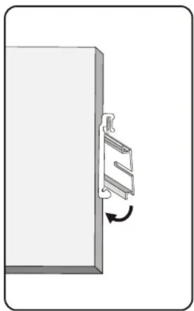
natural_image
Diagram of a door handle with a mechanical component and rotation arrow (no text or symbols)Montage des Switches Entfernen des Switches

Anschlussblock

Vorsicht:
1111 W. 35th Street, Chicago, IL 60609 USA • tripplite.com/support