
B040-008-19 - Switch Tripp Lite - Free user manual and instructions
Find the device manual for free B040-008-19 Tripp Lite in PDF.
| Product Type | KVM Console Switch with integrated 19" LCD, keyboard and touchpad |
| Brand | Tripp Lite |
| Model | B040-008-19 |
| Number of CPU Ports | 8 (HD15 female connectors) |
| Maximum Supported Resolution | 1366 x 768 |
| Power Supply | Internal, 100-240 V, 50/60 Hz (C13 power cord included) |
| Dimensions (W x H x D) | 48.25 x 4.5 x 71 cm |
| Weight | Approximately 12 kg |
| Rack Mounting | Yes, 19-inch standard (1U) |
| Integrated Console | 19" LCD, keyboard, 2-button touchpad |
| Port Selection | Pushbuttons, keyboard hotkeys, On-Screen Display (OSD) |
| Password Protection | Yes, single |
| Firmware Upgrade | Yes, via included HD15 to DB9 cable |
| Daisy Chain Expansion | Up to 16 levels, 256 computers maximum |
| Auto Scan | Yes, configurable (active ports, Easy View, etc.) |
| Easy View Function | Allows setting specific ports for auto scanning |
| External Connectors | 1x VGA HD15 (external monitor), 1x USB (external keyboard/mouse), firmware upgrade port |
| External Console Port | VGA and USB at rear |
| Remote IP Access | Yes, via B051-000 adapter (sold separately) |
| Supported Operating Systems | Windows 95+, Mac OS 10.4+, Linux, Sun Solaris |
| Operating Temperature | 0 to 40 °C |
| Operating Humidity | 0 to 90% RH non-condensing |
| Warranty | 1 year limited |
| Package Contents | Switch, firmware upgrade cable, power cord, quick start guide, manual CD, mounting hardware |
Frequently Asked Questions - B040-008-19 Tripp Lite
User questions about B040-008-19 Tripp Lite
0 question about this device. Answer the ones you know or ask your own.
Ask a new question about this device
Download the instructions for your Switch in PDF format for free! Find your manual B040-008-19 - Tripp Lite and take your electronic device back in hand. On this page are published all the documents necessary for the use of your device. B040-008-19 by Tripp Lite.
USER MANUAL B040-008-19 Tripp Lite
NetController™ Console KVM and Rackmount KVM Switches
Models: B040-008-19, B040-016-19, B042-004, B042-008 and B042-016
Series No: AGCB6533
- Features 2
1.1 General Features 2
1.2 Package Contents 2
1.3 Hardware/Software Support 2
1.4 Cable Requirements 2
1.5 External Views 3
- Installation 5
2.1 Rackmounting Guidelines 5
2.2 Rackmounting Instructions.. 5
2.3 Connecting PCs and Peripherals to a Single Switch....5
2.4 Daisy-Chaining 6
- Operation 7
3.1 Control Interfaces 7
3.1.1 Push Buttons.. 7
3.1.2 Keyboard Hotkeys 7
3.1.3 On-Screen Display 7
3.2 OSD Main Menu 8
3.2.1 Switching Ports Via OSD Main Menu 8
3.2.2 Editing Port Names 8
3.2.3 Setting Ports as Easy View Ports.. 8
3.2.4 Exiting the OSD.. .8
3.2.5 Logging Out of the KVM Switch.. 8
3.2.6 Initiate an Auto Scan.. 8
3.2.7 Navigate to the OSD Setup Page 8
3.3 OSD Setup Page 9
3.3.1 AutoLogout.. 9
3.3.2 OSD Timeout 9
3.3.3 Auto Scan Period 9
3.3.4 Title Bar 9
3.3.5 Hotkey. 9
3.3.6 Password 9
3.3.7 Load Default.. 10
3.3.8 OSD Appearance.. 10
3.3.9 Auto Scan Mode 10
3.3.10 Status Page 10
3.4 Upgrade Firmware 10
- Technical Specifications 12
- Warranty and Product Registration 12
Espanol 13
Francais 25
WARRANTY REGISTRATION
Register your product today and be automatically entered to win an ISOBAR® surge protector in our monthly drawing!

triplite.com/warranty


Manufacturing Excellence.
1111 W. 35th Street, Chicago, IL 60609 USA triplite.com/support
Note: Follow these instructions and operating procedures to ensure correct performance and to prevent damage to this unit or to its connected devices.
Copyright © 2021 Tripp Lite. All rights reserved. All trademarks are the property of their respective owners.
1. Features
1.1 General Features
- B040-Series Console KVM Switches come with a built-in 19 in. LCD, keyboard and touchpad
- Connect up to 256 computers by daisy-chaining up to 16 levels* of NetController KVM Switches
- Compatible with standard 19-inch racks
- Access connected computers via Push-button, OSD or Hotkey Commands
- Password protection
- Firmware upgradeable
B042-Series Rackmount KVM Switches support USB and PS/2 keyboard/mice on both the console and connected computers - B040-Series Console KVM Switches come with an external USB keyboard/mouse port and VGA monitor port
- B040-Series Console KVM Switches include a User Convenience Ground
- P780-Series USB/PS2 Combo KVM Cable Kits eliminate the need to buy separate USB and PS/2 KVM cable kits
- Remotely access connected computers by connecting a B051-000 IP Remote Access Unit
B040-Series Console KVM Switches support resolutions up to 1366 x 768; B042-Series Rackmount KVM Switches support resolutions up to 2048 x 1536
When daisy-chaining (16) 16-Port KVM switches together. *Previous versions of NetController KVM Switches have a daisy-chain limitation. If you experience problems daisy-chaining over 8 levels, you may need to upgrade the firmware of your unit(s). Additionally, confirm daisy chain unit(s) have the same hardware version. B040-Series KVM Switches should be the primary switch. If old hardware and new hardware switches are daisy chained together, the new hardware must be the primary KVM switch.
1.2 Package Contents
- B040-Series Console KVM Switch or B042-Series Rackmount KVM Switch
- HD15 to DB9 Firmware Upgrade Cable, 4 ft.
Daisy-Chain Cable (B042-Series KVM Switches only), 8 in.
C13 to 5-15P Power Cord (B040-Series Console KVM Switches only), 6 ft. - External Power Supply - Input: 100-240V, 50/60Hz, 0.3A Output: 9V, 1A (B042-Series Rackmount KVM Switches only)
Daisy-Chain Terminator (B042-Series Rackmount KVM Switches only)
External VGA Port Terminator (B040-Series Console KVM Switches only) - Rackmount Hardware
Owner's Manual CD
Quick Start Guide
1.3 Hardware/Software Support
Supports standard 5-button Microsoft, Logitech or comparable Mice
Supports standard Microsoft, Logitech and comparable keyboards
- Compatible with Windows® 95 and above, Mac® OS 10.4 and above, Linux and Sun Solaris
- B040- and B042-Series KVM Switches support resolutions up to 2048 x 1536
1.4 Cable Requirements
C13 Power Cord (B040-Series Console KVM Switches only)
- External Power Supply* (B042-Series KVM Switches only)
Tripp Lite P780-Series USB/PS2 Combo KVM Cable Kit
Tripp Lite P781-Series Daisy-Chain Cable
- HD15 Female to DB9 Male Firmware Upgrade Cable
Daisy-Chain Terminator (B042-Series KVM Switches only)
External VGA Port Terminator (B040-Series Console KVM Switches only)
*Use only the external power supply that is included with the B042-Series KVM Switch.
1. Features
1.5 External Views
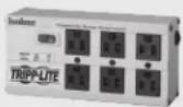
Console KVM Switch Front View
Upper Handle: Pull to slide the KVM Switch out; push to slide the KVM Switch in.
19" LCD Display: Built-in on-screen display (OSD) for convenient KVM Switch control, including port selection.
3 OSD Push Buttons: Used to access the OSD Menu to adjust the LCD display.
4 LED Indicators: The red LEDs will illuminate above each port with a connected computer that is running power through the console interface. If the connected computer is powered off, the red LED will not be illuminated. The green LEDs will illuminate above the computer port that is currently selected as active.
5 Port Selection Buttons: Push to directly select the active computer channel that can be controlled by the shared keyboard, touch pad and LCD display
3 Keyboard
7 2-Button Touch Pad: Left button is left click, right is right click. Run your finger up or down the far right side of the touch pad to scroll up and down a screen.
Rackmounting Brackets: There are rackmount brackets to secure the chassis to a system rack located at each corner of the unit.
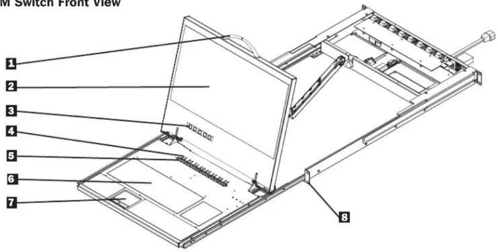
Rackmount KVM Switch Front View
1 Port Selection Buttons: Push to directly select the active computer channel that can be controlled by the shared keyboard, monitor and mouse.
Bank LED Display: Shows the position of the B042-Series KVM Switch in a daisy-chain installation.
Live LED Indicators: A red LED will illuminate when the corresponding port has a computer that is both connected and powered-on.
4 Selected LED Indicators: A green LED will illuminate when the computer connected to the corresponding port has the KVM's focus.
1. Features
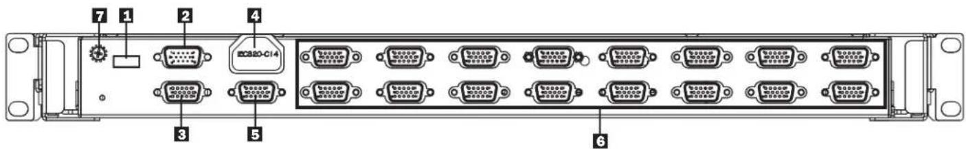
Console KVM Switch Rear View
External USB Keyboard/Mouse Port: This USB port is available if you want to use an external keyboard or mouse. It can also be used if connecting a B051-000 IP Remote Access Unit.
Firmware Upgrade Port: During a firmware upgrade, the included HD15 to DB9 Firmware Upgrade Cable connects to the KVM switch here.
Daisy-Out Port: When daisy-chaining additional B042-Series KVM Switches, the daisy-chain cable connects from this port to the lower-level KVMs. Daisy-Chain In port.
4 Power Dongle: The included C13 to 5-15P power cord connects to the KVM switch here.
External VGA Monitor Port: This HD15 port is available if you want to use an external monitor. It can also be used if connecting a B051-000 IP Remote Access Unit.
Note: If this port is not being used, the included External VGA Port Terminator must be connected to it for the unit to function properly.
Computer Ports: Computers connect to the KVM switch here via P780-Series USB/PS2 Combo KVM Cable Kits.
7 User Convenience Ground (Console Only)
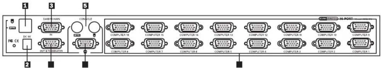
Rackmount KVM Switch Rear View
1 USB Keyboard/Mouse Console Ports: Two USB ports are available to connect a USB keyboard and/or mouse.
2 PowerReceptacle:The included External Power Supply connects to the KVM switch here.
3 Daisy-Chain In/Firmware Upgrade Port: This HD15 Male connector is used when daisy-chaining to a higher-level B040/42-Series KVM Switch. When the B042-Series KVM Switch is the first KVM in a daisy-chain, or in single-stage installations, the included HD15 to DB9 Firmware Upgrade Cable connects to the KVM switch here to perform a firmware upgrade.
Note: When performing a firmware upgrade on a daisy-chain installation, upgrading the Master KVM switch will also upgrade all lower-level KVM switches. (See Firmware Upgrade on page 10 for details.)
4 Daisy-Chain Out Port: This HD15 Female connector is used when daisy-chaining to a lower-level B042-Series KVM Switch.
PS/2 Keyboard/Mouse Console Ports: Two PS/2 ports are available to connect a PS/2 keyboard and/or mouse.
3 VGA Monitor Console Port: The console monitor connects to the KVM switch here.
Computer Ports: Computers connect to the KVM switch here via P780-Series USB/PS2 Combo KVM Cable Kits.
2. Installation
2.1 Rackmounting Guidelines
- The ambient operating temperature in a rack can be an issue, and is dependent upon the rack load and ventilation. When installing in a closed or multi-unit rack assembly, make sure that the temperature does not exceed the maximum rated ambient temperature.
- Ensure that airflow within the rack is not compromised.
To protect against circuit overloading, you should plug the KVM switch and connected computers into a Tripp Lite SmartPro or SmartOnline UPS System. - Reliable grounding of rackmounted equipment should be maintained.
2.2 Rackmounting Instructions
Standard Rackmount KVM Switch Instructions
Depending on whether you want to mount the KVM switch to the front or back of the rack, attach the included rackmount brackets to the front or rear sides of the KVM switch.
2 Using user-supplied screws, mount the rackmount brackets of the KVM switch to the rack.
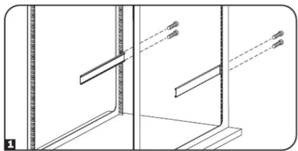
Standard Console KVM Switch Instructions
The B040-Series Console KVM Switches come with removable rackmount brackets, allowing the unit to be installed by a single person.
1 Remove the rackmount brackets from the unit and mount them to the back of the rack using user-supplied screws.
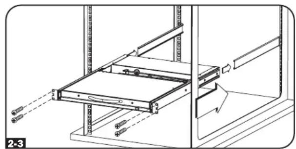
2 Take the Console KVM switch and gently slide it into the rack so that it slides into the rackmount brackets you just mounted.
3 Mount the rackmount brackets on the front of the unit to the rack using user-supplied screws.
2-Post Rack Console KVM Switch Instructions
The B040-Series Console KVM Switches can be mounted to a 2-Post Rack using Tripp Lite's B019-000 2-Post Rackmount Kit (sold separately). See the B019-000 owner's manual for installation instructions.
Note: Connect the User Convenience Ground, if desired.
2.3 Single-Stage Installation
In a single-stage installation, there is only one B040/42-Series KVM Switch being used to connect to multiple computers.
Before starting the installation, shut down all computers that are to be connected to the KVM switch.
Connect the external power supply (B042-Series KVMs) or power cord (B040-Series KVMs) to the unit, and then plug it into a Tripp Lite Surge Protector, PDU or Uninterruptible Power Supply (UPS).
B042-Series KVM Switches Only: Connect a USB or PS/2 keyboard, mouse and a monitor to the console ports on the back of the KVM switch. Note:
Any combination of mouse and keyboard will work; PS/2 keyboard and mouse, USB keyboard and mouse, PS/2 keyboard and USB mouse, USB keyboard and PS/2 mouse. USB ports are to be used for USB only. Do not connect any PS2 to USB connections or peripherals.
B040-Series Console KVM Switches Only: Connect an external USB mouse or keyboard, and an external monitor to the corresponding external console ports on the back of the unit. You can also add remote access to the KVM switch by connecting a B051-000 IP Remote Access unit to the external console ports on the back of the unit. (See the B051-000 manual for details on installation.)
Note: If you are not using the External VGA Monitor port, you must connect the External VGA Port Terminator to it for the unit to function properly.
5 Using Tripp Lite P780-Series USB/PS2 Combo KVM Cable Kits, connect a computer to an available computer port on the back of the unit. Repeat this step for each additional computer you are connecting.
6 Power on the connected computers.
2. Installation
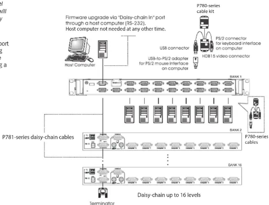
2.4 Daisy-Chaining
Warning! The total length of daisy-chain cabling from the master KVM switch to the last KVM switch in a daisy-chain installation (regardless of the number of levels) must not exceed 98 ft. (30 m). If the total length of daisy-chain cabling exceeds 98 ft. (30 m), the installation will not function properly. Note: Previous versions of NetController KVM Switches have a daisy-chain limitation. If you experience problems daisy-chaining over 8 levels, you may need to upgrade the firmware of your unit(s). Additionally, confirm daisy chain unit(s) have the same hardware version. B040-Series KVM Switches should be the primary switch. If old hardware and new hardware switches are daisy chained together, the new hardware must be the primary KVM switch.
To increase the number of connected computers up to 256^ , up to 16 levels of NetController KVM Switches can be daisy-chained together. The diagram and steps below describe how to set up a daisy-chain installation.
*When (16) 16-Port KVM switches are daisy-chained together.
Step 1: Connect the external power supply (B042-Series KVMs) or power cord (B040-Series KVMs) to the Master KVM switch, then plug it into a Tripp Lite Surge Protector, PDU or Uninterruptible Power Supply (UPS).
Note: B040-Series Console KVM Switches can only occupy the first position in a daisy-chain.
Step 2: B042-Series KVM Switches Only: Connect a USB or PS/2 keyboard, mouse, and a monitor to the console ports on the back of the Master KVM switch.
Note:
Any combination of mouse and keyboard will work; PS/2 keyboard and mouse, USB keyboard and mouse, PS/2 keyboard and USB mouse, USB keyboard and PS/2 mouse.
- USB ports are to be used for USB only, do not connect any PS2 to USB connections or peripherals.
Step 3: B040-Series Console KVM Switches Only: Connect an external USB mouse or keyboard, and an external monitor to the corresponding external console ports on the back of the Master Console KVM switch. You can also add remote access to the KVM switch by connecting a B051-000 IP Remote Access unit to the external console ports on the back of the unit. (See the B051-000 manual for details on installation.)
Note: If you are not using the External VGA Monitor port, you must connect the External VGA Port Terminator to it for the unit to function properly.
Step 4: Using the included 8 in. Daisy-Chain Cable, or a P781-Series Daisy-Chain Cable (sold separately), connect the Daisy-Chain Out port of the Master KVM switch to the Daisy-Chain In port of the second-level B042-Series KVM Switch.
Note: The maximum distance between any two daisy-chained KVM switches is 98 ft (30 m)*.
Step 5: Connect the external power supply to the second-level B042-Series KVM Switch and then plug it into a Tripp Lite Surge Protector, PDU or Uninterruptible Power Supply (UPS). Repeat steps 4 and 5 for any additional KVM switches you are adding, with no more than 16 KVM switches in the entire installation.
Step 6: After you have daisy-chained all of the KVM switches, connect the Daisy-Chain Terminator that came with your B042-Series KVM Switch to the Daisy-Chain Out port of the last KVM in the installation.
Step 7: Using Tripp Lite P780-Series USB/PS2 Combo KVM Cable Kits, connect a computer to an available computer port on the installation. Repeat this step for each additional computer you are connecting.
Step 8: Power on the connected computers.
Note: During the daisy chain installation, the Master/Lower Level will not enable the daisy chain connection and the LED display will display 01/01. In order to enable, the user will have to press any button on the Master unit and the Lower Level unit's LED will display 01/02.
- Previous versions of NetController KVM Switches may not support these distances. If you experience problems when daisy-chaining within the max distance requirements, you may need to upgrade the firmware of your unit. (See page 10 for details on performing a firmware upgrade.)
Warning! Total daisy-chain cabling distance from the master KVM switch to the last KVM switch must not exceed 98 ft. (30 m).
3. Operation
This chapter provides general guidelines for KVM Switch operation. It is strongly recommended that you read this chapter in advance of operating your NetController KVM Switch.
3.1 Control Interfaces
There are three ways to operate your NetController KVM Switch—Push buttons, Keyboard Hotkeys or the OSD Menu. The operation of these three control methods is detailed below.
3.1.1 Push Buttons
The push buttons are used to directly select the active computer channel that can be controlled by the shared keyboard, mouse and monitor. Pressing a front-panel button during normal operation will cause the corresponding channel to be selected.
3.1.2 Keyboard Hotkeys
Hotkey commands are a convenient way to switch ports or perform basic operations on the KVM switch using only your keyboard. By default, all hotkey commands are started by pressing the [Scroll Lock] key twice, and then completed with a series of keystrokes. The preceding hotkey can be changed from [Scroll Lock] to [Caps Lock], [Num Lock] or [F12]. (See page 9 for details on changing the hotkey.)
Hotkey Command* = [Scroll Lock], [Scroll Lock], Command Key/Sequence
*Hotkeys in a hotkey command must be pressed within 2 seconds of each other for the command to be successful.
The following table lists all of the hotkey commands that can be performed on the KVM switch and provides a description of what they do.
| Hotkey Command Hotkey | Sequence1 | Description |
| Select Port(Single-Stage Installation) | [Scroll Lock], [Scroll Lock], abab = 2-Digit Port Number (01 - 16) | Switches console focus to the selected port. |
| Select Port(Daisy-Chain Installation) | [Scroll Lock], [Scroll Lock], ab, yzab = 2-Digit Station Number (01 - 16)yz = 2-Digit Port Number (01 - 16) | Switches console focus to the selected KVM switch and port. |
| Next Lower Port | [Scroll Lock], [Scroll Lock], [↓] | Switches console focus from the current port to the next accessible port prior to it. |
| Next Higher Port | [Scroll Lock], [Scroll Lock], [↑] | Switches console focus from the current port to the next accessible port after it. |
| Next Lower Station | [Scroll Lock], [Scroll Lock], [Page Up] | Switches console focus from the current port to the first accessible port on the next lower-level KVM switch. |
| Next Higher Station | [Scroll Lock], [Scroll Lock], [Page Down] | Switches console focus from the current port to the last accessible port on the next higher-level KVM switch. |
| Beep On/Off | [Scroll Lock], [Scroll Lock], [B] | Toggles the Beeper On/Off. The Beeper sounds when performing a Hotkey Command or during an Auto Scan. |
| Initiate an Auto Scan | [Scroll Lock], [Scroll Lock], [S] | Initiates an Auto Scan. Press any key to stop an Auto Scan. |
| Title Bar On/Off | [Scroll Lock], [Scroll Lock], [T] | Turns the Title Bar On/Off.Note: This does not affect the Title Bar setting in the OSD. |
| Reset Console Mouse | [Scroll Lock], [Scroll Lock], [End] | Reset the console mouse in the event of a lockup. |
| Open the OSD Menu | [Scroll Lock], [Scroll Lock], [Spacebar] | Opens the OSD Menu. |
| Change the HotkeyPreceding Sequence | [Scroll Lock], [Scroll Lock], [H], yy = [Scroll Lock], [Caps Lock], [Num Lock] or [F12] | Changes the hotkey preceding sequence to [Scroll Lock], [Caps Lock], [Num Lock] or [F12]. |
| Last Known Active PortRestore | [Scroll Lock], [Scroll Lock], [L] | Enables/Disables the feature that restores the KVM switch to the last port to have the KVMs focus prior to a power failure. |
Hotkeys in a hotkey command must be pressed within 2 seconds of each other for the command to be successful.
3.1.3 On-Screen Display (OSD)
The On-Screen Display (OSD) is a text-based interface used to navigate between ports and perform operations on the KVM switch. The OSD can be displayed by pressing the hotkey command [Scroll Lock], [Scroll Lock], [Spacebar]. The following section describes the features of the OSD and how to use them.
3. Operation
3.2 OSD Main Menu
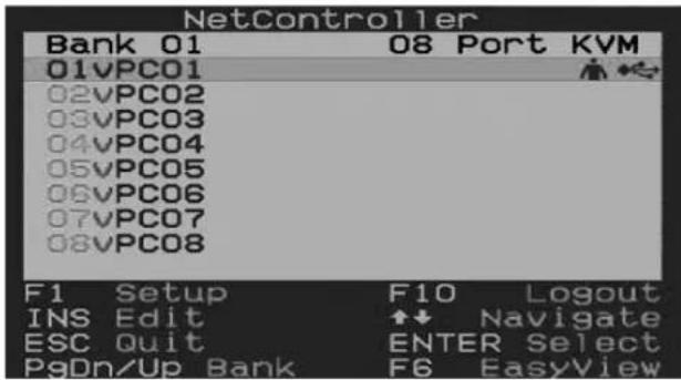
Upon opening the OSD, the OSD Main Menu is the first screen to appear. The OSD Main Menu displays the ports on the KVM installation and allows you to switch between them. In addition, the OSD Main Menu allows you to edit port names, mark ports as Easy View ports and navigate to other OSD pages. The following section describes the various features of the OSD Main Menu.
The Bank Number of the KVM switch being displayed by the OSD Main Menu is shown in the upper-left corner. The Bank Number tells you the position of the KVM switch whose port you are currently viewing.
The first column of the OSD Main Page displays the port number of the selected KVM switch, and the second column displays the port name. Each port name can be given a unique name by using the OSD Main Menu's Edit feature. By default, ports are named as PC01, PC02, PC03, etc.
- Port rows that contain the icon have computers connected to them using the PS/2 keyboard and mouse connectors of the P780-Series KVM Cable Kit. Port rows that contain the icon have computers connected to them using the USB keyboard/mouse connector of the P780-Series KVM Cable Kit. Port rows that contain the icon currently have the consoles focus. If you exit the OSD, this is the port that will be displayed.
- Port rows that do not contain any icons either do not have a computer connected to them or they have a computer connected to them that is powered off.
3.2.1 Switching Ports via the OSD Main Menu
To switch ports using the OSD Main Menu, highlight a port by using the up and down arrow keys. As the OSD Main Menu only displays 8 ports at a time, use the [Page Up] and [Page Down] keys to navigate between ports on KVM switches and Daisy-Chained KVM Switches. Once the desired port is highlighted, press the [Enter] key to access the port and close the OSD.
3.2.2 Editing Port Names
To edit a port's name, highlight it and press the [Insert] key. This will allow you to enter in a port name with a maximum of 16 characters (A-Z, 0-9).
3.2.3 Setting Ports as Easy View Ports
Easy View ports give users a more convenient way to choose which ports are accessed during an Auto Scan. The user has the ability to set an Auto Scan to only access those ports that are marked as Easy View, limiting the scan to only the computers that the user wishes to monitor. By default, all ports on the installation are set as Easy View ports. To toggle Easy View On/Off, highlight a port and press the [F6] key. A "v" next to the port number indicates it is an Easy View port.
3.2.4 Exiting the OSD
To exit the OSD, simply press the [Esc] key. Regardless of which OSD screen you are in, pressing the [Esc] key will always exit the OSD.
3.2.5 Logging Out of the KVM Switch
To log out of the KVM Switch, press the [F10] key. This will close the OSD and display the currently selected port and a password prompt. You will not be able to access the connected computer until you enter the correct password. Once the correct password is entered, the port will be released for use.
Note: Pressing the [F10] key when the Password feature is disabled will still close the OSD and display the currently selected port and password prompt; however, you can simply press the [Esc] or [Enter] key to release the port for use.
3.2.6 Initiate an Auto Scan
To start an Auto Scan, press the [F2] key while in the OSD, regardless of which OSD screen you are in. Press any key to stop an Auto Scan.
3.2.7 Navigate to the OSD Setup Page
To navigate to the OSD Setup Page from the OSD Main Menu, press the [F1] key. The features of the OSD Setup Page are described in the following section.
3. Operation
3.3 OSD Setup Page
The OSD Setup Page allows you to configure the settings of the KVM switch, and to enable/disable password security. The settings in the OSD Setup Page are described in the following sections.
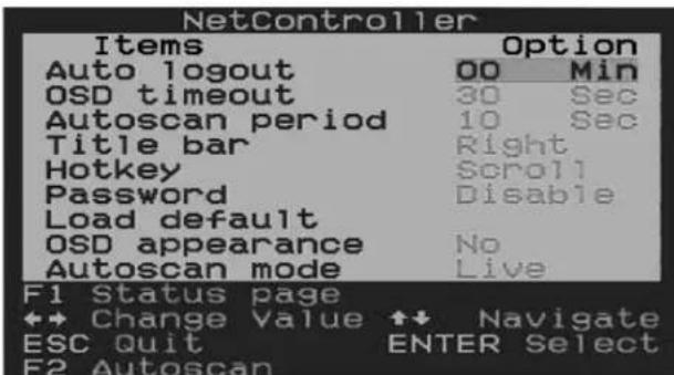
3.3.1 AutoLogout
The AutoLogout setting allows you to determine the amount of inactivity time required before the user is logged out of the KVM switch and required to enter a password to regain access. An AutoLogout is only performed when out of the OSD and accessing a connected computer. It does not apply when the user is inside the OSD. To edit the AutoLogout setting, highlight it and use the [] and [] keys to set a value between 00 and 99 minutes, in which a setting of 00 disables the feature. Once entered, press the [Enter] key to save the setting. The AutoLogout setting is disabled (00) by default.
Note: The AutoLogout function will not work unless the Password feature is enabled.
3.3.2 OSD Timeout
The OSD Timeout setting allows you to determine the amount of inactivity time that must pass until the OSD is closed. This feature simply closes the OSD, and does not log you out. To edit the OSD Timeout setting, highlight it and use the [] and [] keys to set a value between 00 and 95 seconds (at intervals of 5), in which a setting of 00 disables the feature. Once entered, press the [Enter] key to save the setting. The OSD Timeout setting is set at 30 seconds by default.
3.3.3 Auto Scan Period
The Auto Scan Period setting determines the amount of time an Auto Scan spends on a port before it continues to the next port. To edit the Auto Scan Period setting, highlight it and use the [] and [] keys to set a value between 5 and 95 seconds (at intervals of 5). Once entered, press the [Enter] key to save the setting. The Auto Scan Period setting is set at 10 seconds by default.
3.3.4 Title Bar
The Title Bar is the indicator that appears on the screen to let you know which port you are accessing. This setting allows the user to choose between the 5 options listed: Disable - The Title Bar does not show up at all. Left - The Title Bar is displayed in the top-left of the screen, and does not disappear. Right - The Title Bar is displayed in the top-right of the screen, and does not disappear. Left - The Title Bar is displayed in the top-left of the screen, and it disappears after 5 seconds. Right - The Title Bar is displayed in the top-right of the screen, and it disappears after 5 seconds. To switch between options, highlight the Title Bar setting and use the [] and [] keys to toggle between them. When you have selected the desired option, press the [Enter] key.
3.3.5 Hotkey
The Hotkey setting allows you to set the preceding hotkey sequence to [Scroll Lock], [Caps Lock], [Num Lock] or [F12]. To switch the preceding hotkey, highlight this setting and use the [] and [] keys to toggle between the options. Press the [Enter] key to save the preceding hotkey choice. This setting defaults at [Scroll Lock].
3.3.6 Password
The Password setting allows you to enable/disable password security. When enabled, a password is required to access the KVM switch once the user is logged out. To change this setting, highlight it and press the [Enter] key. A prompt will appear asking if you want to enable the password. Yes enables the password and No disables it. When enabling the password, you will be asked to enter a new password, and then enter it again to confirm it. Once enabled, the password entered here is required to gain access to the KVM switch when a user has been logged out. To disable password security, you will be prompted to enter the previous password. Once the previous password is entered correctly, the password feature is disabled. This feature is disabled by default.
3. Operation
3.3.7 Load Default
The Load Default setting allows you to restore the OSD's factory default settings (Port Names, Auto Scan Period, Title Bar, etc.). Restoring the OSD's factory default settings will not affect the KVMs password security. To restore the default settings, highlight the Load Default settings and press the [Enter] key. You will be prompted to verify that you want to restore the OSD's factory default settings. If yes, highlight the yes option and press the [Enter] key.
3.3.8 OSD Appearance
The OSD Appearance setting allows you to keep the OSD open after switching ports via the OSD Main Menu. To turn this setting on, highlight it and press the [] and [] keys to toggle it On/Off, and then press the [Enter] key. This setting is turned off by default.
3.3.9 Auto Scan Mode
The Auto Scan Mode setting allows you to specify which ports are accessed during an Auto Scan. You can choose from the following options: All - All ports will be scanned, regardless of whether they have a computer connected to them or not. Live - Only ports that have a connected computer that is powered on will be accessed EzV - All ports that are marked as Easy View ports will be scanned, regardless of whether they have a computer connected to them or not. EzV + Live - Only ports that are marked as Easy View ports and have a connected, powered on computer will be accessed. To switch between these options, highlight the Auto Scan Mode setting and use the [] and [] keys to toggle between them. When you have selected the desired option, press the [Enter] key.
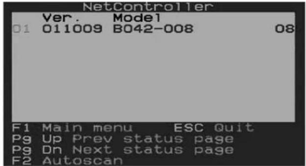
3.3.10 Status Page
When in the OSD Setup Page, press the [F1] key to switch to the OSD Status Page. The OSD Status Page displays all of the KVM switches in the installation and their firmware version numbers. When in the OSD Status Page, press the [F1] key to switch to the OSD Main Menu.
3.4 Upgrade Firmware
All firmware upgrades for the B040/042-Series KVM Switches will be available in the Support Section at tripplite.com (if there are no updates posted, none are currently available). Before downloading the firmware files, verify the firmware version on the website is more current that that of your KVM switch. You can find your KVM switch's firmware version by navigating to the Status Page in the OSD.
Note: A new hardware version (v2) of the B040-008-19 was released in 2019, requiring different firmware from the previous version (v1). The Support tab of this page includes a zip folder for v2. Along with the applicable firmware, it contains an FW Notes file to help you determine which hardware version you have and which firmware to use. The current firmware comes preinstalled on all v2 models. If you have a hardware version (v1) KVM, consult Technical Support for the applicable firmware.
You can also use the Firmware Upgrade Utility to check your firmware version. (See below) To perform a firmware upgrade, follow these instructions:
Step 1: Using the provided Firmware Upgrade Cable, connect a standalone computer (one not already connected to the KVM Switches Server Port) to the KVM Switch. If you have multiple KVM Switches daisy-chained together, connect the Firmware Upgrade Cable to the Master KVM Switch (the first KVM in the daisy-chain). All KVM switches daisy-chained from the Master KVM switch will be upgraded simultaneously.
Step 2: Go to the Support section of triplite.com and download the firmware upgrade utility and upgrade file.
Step 3: Before upgrading the firmware on your NetController KVM Switch, disable all running programs (anti-virus, system monitoring, etc.) on the standalone computer you are using to perform the upgrade. These programs may prevent the firmware upgrade from completing successfully.
Step 4: Locate the .exe file you just downloaded and double-click on it. The KVM Upgrade Utility screen will open.
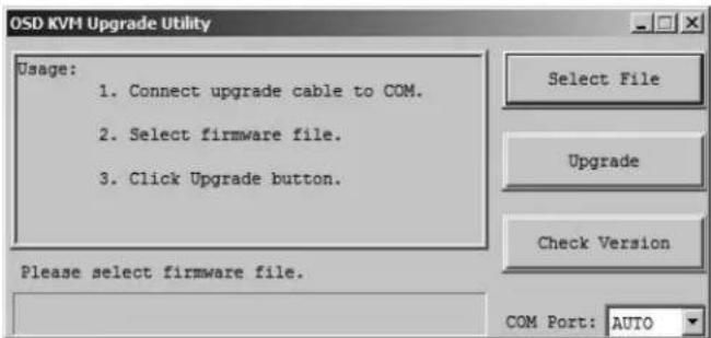
3. Operation
Step 5: Click the Select File button and find the firmware upgrade file that you just downloaded.
Step 6: If you have not yet verified your KVM Switches firmware version number via the OSD Status page, click the Check Version button. This will compare your KVM Switches firmware to the firmware upgrade file you just downloaded. If your KVM has more recent firmware, the Firmware Upgrade Utility will ask you if you wish to continue.
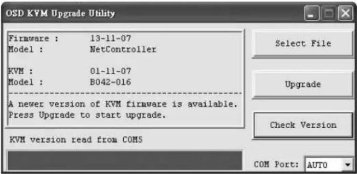
If so, click the Upgrade button to start the upgrade. If not, close out of the Firmware Upgrade Utility. If your KVM Switch has older firmware than the downloaded file, click on the Upgrade button to start the upgrade. (Upon clicking the Upgrade button, you will be notified that the video, keyboard and mouse will be locked up during the upgrade process. Click Yes to continue or no to exit.)
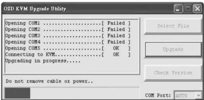
Step 7: During the firmware upgrade process, your KVM switch console will go blank and you will not be able to use the keyboard or mouse. Functionality will return upon firmware completion. The Firmware Upgrade Utility will notify you if the update was successful or not. If the upgrade fails, see the Troubleshooting section below.
Note: It is recommended that after any firmware upgrade, The B040 & B042 Series be restarted (powered down, then reapply power) before using the switches.
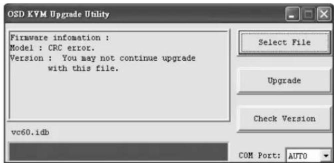
Firmware Upgrade Troubleshooting
If the firmware upgrade fails due to timeout, stalls at any point for a long period of time or fails due to power outage, check to make sure all running programs (anti-virus, system monitoring, etc.) are turned off. When you have determined all programs are disabled, unplug and re-plug the firmware upgrade cable and try the upgrade procedure again.
If you find that your keyboard and mouse are no longer working during a firmware upgrade failure, temporarily connect them to the host PC until you can finish the upgrade. Once completed, your KVM console should again be working properly.
Note: During the daisy chain installation, the Master/Lower Level will not enable the daisy chain connection and the LED display will display 01/01. In order to enable, the user will have to press any button on the Master unit and the Lower Level unit's LED will display 01/02.
4. Technical Specifications
| Model B042-004 B042-008 B040-008-19 B040-016-19 B042-016 | |||||
| # of CPU Ports (x4) HD15 F (x8) HD15 F (x16) HD15 F | |||||
| KVM Cable Kits P780-Series USB/PS2 Combo KVM Cable Kits | |||||
| Port Selection Push buttons, Hotkeys, OSD | |||||
| Password Security Yes (Single Password) | |||||
| Built-In Console No No | Yes (19-in. LCD) | No | |||
| External Console Ports | HD15 F, (x2) USB A F, (x2) MiniDIN6 F | USB A F, HD15 F | HD15 F, (x2) USB A F, (x2) MiniDIN6 F | ||
| IP Remote Access | Yes, with B051-000 IP Remote Access Unit (Sold Separately) | ||||
| Expandable | Yes; Daisy-Chain up to 16 levels | ||||
| Daisy-Chain Cable P781 | Series Cables | ||||
| Max # of Connected CPUs | 244 | 248 | 256 | ||
| Max Resolution | 2040 x 1536 | ||||
| Internal/External Power Supply | External Input: 100-240V, 50/60 Hz, 0.5~1A Output: 9V 1.3A | Internal: 100-240V, 50/60Hz | External Input: 100-240V, 50/60 Hz, 0.5~1A Output: 9V 1.3A | ||
| User Convenience Ground | No | Yes | No | ||
| Operating Temperature | 32°F to 104°F / 0°C to 40°C | ||||
| Storage Temperature | -4°F to 140°F / -20°C to 60°C | ||||
| Humidity | 0 to 90% RH, Non-Condensing | 20 to 90%, Non-Condensing | 0 to 90% RH, Non-Condensing | ||
| Dimensions (H x W x D) | 1.75 x 19 x 6.5 in. / 44.5 x 482.6 x 165 mm | 1.75 x 19 x 28 in. / 44.5 x 482.6 x 711 mm | 1.75 x 19 x 6.5 in. / 44.5 x 482.6 x 165 mm | ||
| Certifications | CE, FCC, RoHS | CE, FCC, RoHS, NOM, cTUV, TUV | CE, FCC, RoHS | ||
5. Warranty and Product Registration
1-YEAR LIMITED WARRANTY: Models B040-008-19 & B040-016-19
3-YEAR LIMITED WARRANTY: Models B042-004, B042-008 & B042-016
Seller warrants this product, if used in accordance with all applicable instructions, to be free from original defects in material and workmanship for a period of 1 year (B040-008-19 and B040-016-19) or 3 years (B042-004, B042-008 and B042-016) from the date of initial purchase. If the product should prove defective in material or workmanship within that period, Seller will repair or replace the product, in its sole discretion. Service under this Warranty can only be obtained by your delivering or shipping the product (with all shipping or delivery charges prepaid) to: Tripp Lite; 1111 W. 35th Street; Chicago IL 60609; USA. Seller will pay return shipping charges. Visit tripplite.com/support before sending any equipment back for repair. This warranty does not apply to equipment, which has been damaged by accident, negligence or misapplication or has been altered or modified in any way. EXCEPT AS PROVIDED HEREIN, TRIPP LITE MAKES NO WARRANTYES, EXPRESS OR IMPLIED, INCLUDING WARRANTY OF MERCHANTABILITY AND FITNESS FOR A PARTICULAR PURPOSE. Some states do not permit limitation or exclusion of implied warranties; therefore, the aforesaid limitation(s) or exclusion(s) may not apply to the purchaser. EXCEPT AS PROVIDED ABOVE, IN NO EVENT WILL TRIPP LITE BE LIABLE FOR DIRECT, INDIRECT, SPECIAL, INCIDENTAL OR CONSEQUENTIAL DAMAGES ASING OUT OF THE USE OF THIS PRODUCT, EVEN IF ADVISED OF THE POSSIBILITY OF SUCH DAMAGE. Specifically, TRIPP LITE is not liable for any costs, such as lost profits or revenue, loss of equipment, loss of use of equipment, loss of software, loss of data, costs of substitutes, claims by third parties, or otherwise.
Product Registration
Visit tripplite.com/warranty today to register your new Tripp Lite product. You'll be automatically entered into a drawing for a chance to win a FREE Tripp Lite product!
- No purchase necessary. Void where prohibited. Some restrictions apply. See website for details.
Use of this equipment in life support applications where failure of this equipment can reasonably be expected to cause the failure of the life support equipment or to significantly affect its safety or effectiveness is not recommended. Do not use this equipment in the presence of a flammable anesthetic mixture with air, oxygen or nitrous oxide.
FCC Notice, Class A
This device complies with part 15 of the FCC Rules, Operation is subject to the following two conditions: (1) This device may not cause harmful interference, and (2) this device must accept any interference received, including interference that may cause undesired operation.
Note: This equipment has been tested and found to comply with the limits for a Class A digital device, pursuant to part 15 of the FCC Rules. These limits are designed to provide reasonable protection against harmful interference when the equipment is operated in a commercial environment. This equipment generates, uses, and can radiate radio frequency energy and, if not installed and used in accordance with the instruction manual, may cause harmful interference to radio communications. Operation of this equipment in a residential area is likely to cause harmful interference in which case the user will be required to correct the interference at his own expense. The user must use shielded cables and connectors with this equipment. Any changes or modifications to this equipment not expressly approved by Tripp Lite could void the user's authority to operate this equipment.
WEEE Compliance Information for Tripp Lite Customers and Recyclers (European Union)

Under the Waste Electrical and Electronic Equipment (WEEE) Directive and implementing regulations, when customers buy new electrical and electronic equipment from
Tripp Lite they are entitled to:
- Send old equipment for recycling on a one-for-one, like-for-like basis (this varies depending on the country)
- Send the new equipment back for recycling when this ultimately becomes waste
Tripp Lite has a policy of continuous improvement. Specifications are subject to change without notice. Photos and illustrations may differ slightly from actual products.


Manufacturing Excellence
1111 W. 35th Street, Chicago, IL 60609 USA · triplite.com/support
Alternatively, you can use the following instructions to implement this operation.
1111 W. 35th Street, Chicago, IL 60609 USA • triplite.com/support
Guide d'utilisation
1111 W. 35th Street, Chicago, IL 60609 USA • triplite.com/support


- NetController™ Console KVM and Rackmount KVM Switches
- WARRANTY REGISTRATION
- Features
- General Features
- Package Contents
- Hardware/Software Support
- Cable Requirements
- External Views
- Installation
- Rackmounting Guidelines
- Rackmounting Instructions
- Standard Rackmount KVM Switch Instructions
- Standard Console KVM Switch Instructions
- 2-Post Rack Console KVM Switch Instructions
- Single-Stage Installation
- Daisy-Chaining
- Operation
- Control Interfaces
- Push Buttons
- Keyboard Hotkeys
- On-Screen Display (OSD)
- OSD Main Menu
- Switching Ports via the OSD Main Menu
- Editing Port Names
- Setting Ports as Easy View Ports
- Exiting the OSD
- Logging Out of the KVM Switch
- Initiate an Auto Scan
- Navigate to the OSD Setup Page
- OSD Setup Page
- AutoLogout
- OSD Timeout
- Auto Scan Period
- Title Bar
- Hotkey
- Password
- Load Default
- OSD Appearance
- Auto Scan Mode
- Status Page
- Upgrade Firmware
- Firmware Upgrade Troubleshooting
- Technical Specifications
- Warranty and Product Registration
- 1-YEAR LIMITED WARRANTY: Models B040-008-19 & B040-016-19
- 3-YEAR LIMITED WARRANTY: Models B042-004, B042-008 & B042-016
- Product Registration
- FCC Notice, Class A
- WEEE Compliance Information for Tripp Lite Customers and Recyclers (European Union)
- Guide d'utilisation
Brand : Tripp Lite
Model : B040-008-19
Category : Switch