
B119-2X2 - Switch Tripp Lite - Free user manual and instructions
Find the device manual for free B119-2X2 Tripp Lite in PDF.


| Product Type | HDMI Matrix Switch |
| Model | B119-2X2 |
| Brand | Tripp Lite |
| Input Ports | 2 x HDMI |
| Output Ports | 2 x HDMI |
| Max Video Resolution | 1080p @ 60 Hz |
| HDCP Support | Yes |
| EDID Support | Yes |
| Control Methods | Pushbuttons, Remote Control, RS-232 Serial |
| Maximum Input Cable Length | 16 ft (5 m) |
| Maximum Output Cable Length | 25 ft (7.6 m) |
| Power Supply Input | 100-240V AC, 50/60 Hz, 0.5A |
| Power Supply Output | 5V DC, 2A |
| Mounting | Wall, Rack, Pole (hardware included) |
| Operating System Compatibility | All (plug-and-play) |
| RS-232 Baud Rate | 57600 or 9600 |
| Remote Control | Yes (included) |
| IR Extension Cable | Not included (only B119-4X4) |
| Compliance | FCC Class B, TAA |
| Warranty | 3-Year Limited |
| Cleaning | Use a soft, dry cloth. No liquid or aerosol cleaners. |
| Safety | Use only with provided power supply. Do not expose to moisture. |
| Spare Parts / Repairability | Not user-serviceable. Contact Tripp Lite support. |
Frequently Asked Questions - B119-2X2 Tripp Lite
User questions about B119-2X2 Tripp Lite
0 question about this device. Answer the ones you know or ask your own.
Ask a new question about this device
Download the instructions for your Switch in PDF format for free! Find your manual B119-2X2 - Tripp Lite and take your electronic device back in hand. On this page are published all the documents necessary for the use of your device. B119-2X2 by Tripp Lite.
USER MANUAL B119-2X2 Tripp Lite
Warranty and Product Registration 10
PROTECT YOUR INVESTMENT!
Register your product for quicker service and ultimate peace of mind.
You could also win an ISOBAR6ULTRA surge protector—a \$100 value!
www.tripplite.com/warranty


Manufacturing Excellence.
1111 W. 35th Street, Chicago, IL. 60609 • www.tripplite.com/support
Copyright © 2018 Tripp Lite. All rights reserved.
Package Contents
• B119-2X2 or B119-4X4 Local Transmitter Unit
- External Power Supply (Input: 100-240V, 50/60 Hz, 0.5A; Output: 5V 2A)*
- IR Extension Cable (B119-4X4 only), 5 ft.
• 3.5 mm to DB9 Adapter Cable
- Mounting Hardware
- Remote Control
- Owner's Manual
*The B119-4X4 comes with a 5V 3A power supply
Product Features
- Share multiple HDMI sources between multiple monitors
- Allows any input to be routed to any output or the same input to be routed to multiple outputs
- Switch between inputs via pushbuttons, remote control, or RS-232 serial
- (For model B119-4X4 only) Extend the remote control range, allow discreet placement of the matrix switch and maintain device switching functionality with the included 5 ft. IR extension cable
• Monitors can be located up to 25 ft. from the switch
• Supports video resolutions up to 1080p @ 60 Hz
• HDCP and EDID compatible - Mounting hardware included
- Plug-and-play—No software or drivers required
- Compatible with all operating systems
- Compliant with the Federal Trade Agreements Act (TAA) for GSA Schedule purchases
Optional Accessories:
• P568-Series High-Speed HDMI Cables
• P520-006 RS-232 Serial Extension Cable
Mounting
The B119-2X2 and B119-4X4 include mounting hardware that allows them to be mounted in a variety of ways. The following images show the different ways the included mounting brackets can be attached.
Note: The images below show a B126-1A1 HDMI over Cat5 Receiver Unit, but the mounting hardware installation is the same for the B119-2X2 and B119-4X4.
Wall-Mount 1 Wall-Mount 2


natural_image
Two black electronic devices with ventilation grilles, one labeled 'TRIO-LITE' and the other showing ports and ventilation slots (no readable text beyond branding)19" Rack-Mount Pole-Mount


natural_image
Two black electronic devices: a circular device with a strap and a vertical stand (no visible text or symbols)Standard Installation
Note: The diagram below shows a B119-2X2 installation. Installation will be the same for the B119-4X4, except for the number of ports.

flowchart
graph TD
    A["Blu-Ray™"] -->|Up to 16 ft.| B["B119-2x2"]
    C["(Optional)"] --> B
    B --> D["Server Rack"]
    D --> E["Computer"]
    B --> F["Up to 25 ft."]
    B --> G["Up to 25 ft."]
    B --> H["Up to 25 ft."]
    B --> I["Up to 25 ft."]
    B --> J["Up to 25 ft."]
    B --> K["Up to 25 ft."]
    B --> L["Up to 25 ft."]
    style B fill:#f9f,stroke:#333
    style D fill:#ccf,stroke:#333
    style E fill:#cfc,stroke:#333
    style F fill:#fcc,stroke:#333
    style G fill:#fcc,stroke:#333
    style H fill:#fcc,stroke:#333
    style I fill:#fcc,stroke:#333
    style J fill:#fcc,stroke:#333
    style K fill:#fcc,stroke:#333
    style L fill:#fcc,stroke:#333
1 Make sure all devices being connected are turned off.
2 Optional: Connect the 3.5 mm to DB9 adapter to the RS-232 serial port on the switch, then to the DB9 serial port on the computer you will be using to control it.
3 Optional (B119-4X4 only): Connect the included IR extension cable to the unit's 3.5 mm IR jack. Position the cable's infrared sensor in an area that allows a direct line of sight between the sensor and the remote.
4 Connect the first HDMI source to the port on the switch marked Source A.
Note: The HDMI cable connecting the source to the switch must be no longer than 16 ft.
5 Repeat step 3 to connect additional HDMI sources to the remaining ports.
Standard Installation
6 Connect the external power supply to the switch and plug it into a Tripp Lite Surge Protector, Power Distribution Unit (PDU), or Uninterruptible Power Supply (UPS). When receiving power, the following LEDs will illuminate: The green Power LED and orange Source LEDs (for the Source ports that have devices connected to them). A green LED will also illuminate to indicate the source that is being transmitted to each Output port.
7 Connect the first HDMI display to the port on the switch marked Output 1.
Note: The HDMI cable connecting the switch to a display must be no longer than 25 ft.
8 Repeat step 7 to connect additional displays to the remaining ports.
9 Turn on the power to the connected devices. The video image should now be displayed on the connected monitors.
10 Press the switch next to each set of Output LEDs to switch the source being displayed on the corresponding Output monitor. You can also use the included remote control to switch between sources. As with the switch next to the Output LEDs, press the button on the remote control of the desired Output port to switch the source being displayed.
Note: The same four-button remote control is included with both the B119-2X2 and B119-4X4. Buttons 3 and 4 will not be used for the B119-2X2.
See the RS-232 Serial Control section in this manual for details on controlling the switch using Terminal Emulation Software.
RS-232 Serial Control
Before using RS-232 Serial Control, you must first go into your Terminal Emulation Software and update the COM port settings.
1 Go to the Setup drop-down menu and select the Serial Port option.
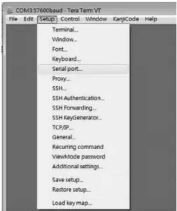
2 Select the COM port that is being used, and update the remaining settings as follows: Baud Rate (57600 or 9600), Data (8 bit), Parity (none), Stop (1 bit), Flow Control (none).
Note: The baud rate in the below image lists 57600; if 57600 does not work, this value should be changed to 9600.

6
RS-232 Serial Control
3 Next, you will need to configure your software to allow input control. Go to the Setup drop-down menu and select the Terminal option.

4 Update the following settings; Receive (LF), Local Echo (enable). The remaining settings can stay as they are.
![Tera Term: Terminal setup Terminal size 98 × 39 Term size = win size Auto window resize Terminal ID: VT100 Answerback: New-line Receive LF Transmit: CR Local echo Auto switch [VT<>TEK] Kanji (receive) UTF-8 7bit katakana Kanji (transmit) UTF-8 7bit katakana Kanji-fin: 7SB Kanji-gut: 7[0] locale: japanese CodePage: 932](/content/2026/06/1225168/images/05edb40691366b92d360579d1ace1b5d71310b647207f492d970d989255293fd.jpg)
RS-232 Serial Control
5 Once these settings are updated, the Terminal Emulation Software will recognize the switch, allowing you to enter commands to control it with. The following table lists the available commands.
| Command Action | |
| sw[x] [n] Switches the source being displayed on the selected output. [x] is the output (1, 2, 3, or 4) and [n] is the desired source (A, B, C, or D). For example, a command of sw1 B would display source B on output 1. | |
| PWD Turns power to the switch on/off. | |
| STE Displays the current output state, showing which source is being displayed on each output. |
Troubleshooting
If you are unable to get an acceptable image after following the installation instructions, try the troubleshooting tips below.
1 Is the external power supply that came with the product connected and plugged into a working power source? For the product to function properly, it must be connected to and receiving power from the external power supply.
2 Was the power to the connected devices turned off prior to installation? If not, restart them.
3 What type of cabling are you using? Inferior cabling can result in poor performance, so it is important that you use cables that can support the video resolution you are trying to obtain. It is recommended that you use Tripp Lite's P568-Series High-Speed HDMI cables, as they have been tested to work with the B119-Series Matrix Switch products.
4 Test your cables to ensure they are working properly. For example, connect your HDMI cables between a source and monitor that you know works to see if the cable is functioning.
5 Is the switch located in an area that exposes it to higher temperatures? If the product is overheated, it will not function properly.
6 What length HDMI cable are you using? The cable connecting a HDMI source to the switch must be no longer than 16 ft. in length. The cable connecting the switch to a display must be no longer than 25 ft. in length.
7 If you are having trouble getting your Terminal Emulation Software to recognize the switch, you may need to shut down your installation and start from the beginning. The 3.5 mm to DB9 adapter cable must be connected first; otherwise the switch will not be recognized.
8 If you are still having trouble getting your Terminal Emulation Software to recognize the switch, check to make sure that your serial settings are set according to the instructions in the RS-232 Serial Control section of this manual.
Warranty and Product Registration
3-Year Limited Warranty
TRIPP LITE warrants its products to be free from defects in materials and workmanship for a period of three (3) years from the date of initial purchase. TRIPP LITE's obligation under this warranty is limited to repairing or replacing (at its sole option) any such defective products. To obtain service under this warranty, you must obtain a Returned Material Authorization (RMA) number from
TRIPP LITE or an authorized TRIPP LITE service center. Products must be returned to TRIPP LITE or an authorized TRIPP LITE service center with transportation charges prepaid and must be accompanied by a brief description of the problem encountered and proof of date and place of purchase. This warranty does not apply to equipment which has been damaged by accident, negligence or misapplication or has been altered or modified in any way.
EXCEPT AS PROVIDED HEREIN, TRIPP LITE MAKES NO WARRANTIES, EXPRESS OR IMPLIED, INCLUDING WARRANTIES OF MERCHANTABILITY AND FITNESS FOR A PARTICULAR PURPOSE. Some states do not permit limitation or exclusion of implied warranties; therefore, the aforesaid limitation(s) or exclusion(s) may not apply to the purchaser.
EXCEPT AS PROVIDED ABOVE, IN NO EVENT WILL TRIPP LITE BE LIABLE FOR DIRECT, INDIRECT, SPECIAL, INCIDENTAL OR CONSEQUENTIAL DAMAGES ARISING OUT OF THE USE OF THIS PRODUCT, EVEN IF ADVISED OF THE POSSIBILITY OF SUCH DAMAGE. Specifically, TRIPP LITE is
not liable for any costs, such as lost profits or revenue, loss of equipment, loss of use of equipment, loss of software, loss of data, costs of substitutes, claims by third parties, or otherwise.
PRODUCT REGISTRATION
Visit www.triplite.com/warranty today to register your new Tripp Lite product.
You'll be automatically entered into a drawing for a chance to win a FREE Tripp Lite product!*
* No purchase necessary. Void where prohibited. Some restrictions apply. See website for details.
FCC Notice, Class B
This device complies with part 15 of the FCC Rules. Operation is subject to the following two conditions: (1) This device may not cause harmful interference, and (2) this device must accept any interference received, including interference that may cause undesired operation.
Note: This equipment has been tested and found to comply with the limits for a Class B digital device, pursuant to part 15 of the FCC Rules. These limits are designed to provide reasonable protection against harmful interference in a residential installation. This equipment generates, uses and can radiate radio frequency energy and, if not installed and used in accordance with the instructions, may cause harmful interference to radio communications. However, there is no guarantee that interference will not occur in a particular installation. If this equipment does cause harmful interference to radio or television reception, which can be determined by turning the equipment off and on, the user is encouraged to try to correct the interference by one or more of the following measures:
- Reorient or relocate the receiving antenna.
- Increase the separation between the equipment and receiver.
- Connect the equipment into an outlet on a circuit different from that to which the receiver is connected.
- Consult the dealer or an experienced radio/TV technician for help.
Any changes or modifications to this equipment not expressly approved by Tripp Lite could void the user's authority to operate this equipment.
Warranty and Product Registration
WEEE Compliance Information for Tripp Lite Customers and Recyclers (European Union)

Under the Waste Electrical and Electronic Equipment (WEEE) Directive and implementing regulations, when customers buy new electrical and electronic equipment from Tripp Lite they are entitled to:
- Send old equipment for recycling on a one-for-one, like-for-like basis (this varies depending on the country)
- Send the new equipment back for recycling when this ultimately becomes waste
WARNING
Use of this equipment in life support applications where failure of this equipment can reasonably be expected to cause the failure of the life support equipment or to significantly affect its safety or effectiveness is not recommended.
Tripp Lite has a policy of continuous improvement. Product specifications are subject to change without notice.


1111 W. 35th Street, Chicago, IL. 60609 • www.tripplite.com/support


- PROTECT YOUR INVESTMENT!
- Package Contents
- Product Features
- Optional Accessories:
- Mounting
- Standard Installation
- RS-232 Serial Control
- Troubleshooting
- Warranty and Product Registration
- 3-Year Limited Warranty
- PRODUCT REGISTRATION
- FCC Notice, Class B
- WEEE Compliance Information for Tripp Lite Customers and Recyclers (European Union)
- WARNING
Brand : Tripp Lite
Model : B119-2X2
Category : Switch