
AC009S - Electronic module IFM - Free user manual and instructions
Find the device manual for free AC009S IFM in PDF.
| Product Type | AS-i safety module for electrical cabinet |
| Brand | IFM |
| Model | AC009S |
| Dimensions (H x W x D) | 114 x 25 x 105 mm |
| Weight | Approx. 150 g |
| Power supply | 26.5 to 31.6 V DC via AS-i, max. current consumption 250 mA |
| Safety inputs | 2 PNP inputs, short-circuit detection |
| Outputs | 2 non-safety LED outputs, 2 non-safety relay outputs (max. 6 A) |
| Communication | AS-i version 2.11/3.0, profile S-7.B.E |
| Ambient temperature | -25 to 50 °C |
| Protection rating | IP20 |
| Housing material | Polyamide (PA) |
| Mounting | On DIN rail 35 mm, vertical or suspended |
| Display | Yellow LED (switching status), green (AS-i), red (fault) |
| Performance Level (PL) | PL e according to EN ISO 13849-1 (category 4) |
| Safety Integrity Level (SIL) | SIL 3 according to IEC 61508 |
| Safety response time | Max. 10 ms |
| Addressing | Via integrated interface, address 1 to 31 (delivery: 0) |
| Maintenance | No maintenance required; clean with dry microfiber cloth |
| Repair | By manufacturer only |
| Approvals | AS-i certified, CE, compliant with Machinery Directive 2006/42/EC |
| Delivery contents | AS-i safety module, user manual, EU declaration of conformity |
Frequently Asked Questions - AC009S IFM
User questions about AC009S IFM
0 question about this device. Answer the ones you know or ask your own.
Ask a new question about this device
Download the instructions for your Electronic module in PDF format for free! Find your manual AC009S - IFM and take your electronic device back in hand. On this page are published all the documents necessary for the use of your device. AC009S by IFM.
USER MANUAL AC009S IFM
Original operating instructions
Safe AS-i module
- According to the machine directive 2006/42/EC the original operating instructions and a translation of these operating instructions into the language or languages of the EU user country must be provided when a unit or protective system is put into operation within the member countries of the European Union (EU).
- If no operating instructions or EC declaration of conformity is supplied with this product in the language of the EU user country, these can be requested from your dealer (see delivery note) or manufacturer (see cover sheet / back).
- Only qualified personnel is allowed to set up the product. Furthermore, we expressly point out that any liability is excluded resulting from putting the unit into operation without the corresponding operating instructions in the language of the EU user country.
ESE\$panol
2 Safety instructions 32
3 Intended use 33
3.1 Safety-related requirements 34
3.2 Safety symbol on the device. 34
3.3 IT safety 34
4 Items supplied 35
5 Function description 35
6 Installation 36
6.1 Installation location 36
6.2 Installation of the device 36
6.3 Identical devices mounted side by side 37
6.4 Deratings for side by side mounting of identical devices 37
6.5 Side by side mounting of different devices 38
6.6 Removing the device 39
7 Electrical connection 39
7.1 General wiring information 39
7.2 Safety instructions relay connections 41
7.3 Connection technology 41
7.4 Connection accessories 41
7.5 Wiring 42
7.5.1 Terminal connection 42
7.6 Block diagram 43
8 Set-up 43
8.1 Addressing 43
9 Operation 43
10 Data bits 44
11 Response times 45
12 Technical data 46
13 Safety characteristics. 48
14 Scale drawing 49
15 Troubleshooting 49
16 Maintenance, repair and disposal 49
1 Preliminary note
You will find instructions, technical data, approvals and further information using the QR code on the unit / packaging or at www.ifm.com.
1.1 Symbols used
√ Requirement
Instructions
Reaction, result
[...] Designation of keys, buttons or indications
Cross-reference

Important note
Non-compliance may result in malfunction or interference.
Information
Supplementary note
1.2Warnings used
| ATTENTION Warning of damage to property | |
| CAUTION Warning of personal injury ► Slight reversible injuries may result. | |
| WARNING Warning of serious personal injury ► Death or serious irreversible injuries may result. |
2 Safety instructions
-
The unit described is a subcomponent for integration into a system.
-
The system architect is responsible for the safety of the system.
-
The system architect undertakes to perform a risk assessment and to create documentation in accordance with legal and normative requirements to be provided to the operator and user of the system. This documentation must contain all necessary information and safety instructions for the operator, the user and, if applicable, for any service personnel authorised by the architect of the system.
-
Read this document before setting up the product and keep it during the entire service life.
- The product must be suitable for the corresponding applications and environmental conditions without any restrictions.
- Only use the product for its intended purpose ( Intended use).
- If the operating instructions or the technical data are not adhered to, personal injury and/or damage to property may occur.
- The manufacturer assumes no liability or warranty for any consequences caused by tampering with the product or incorrect use by the operator.
- Installation, electrical connection, set-up, programming, configuration, operation and maintenance of the product must be carried out by personnel qualified and authorised for the respective activity.
- Protect units and cables against damage.
- Replace damaged units, otherwise the technical data and safety will be impaired.
- Observe applicable documents.
3 Intended use
The safe AS-i module detects safety-related switching states, e.g. of 1- or 2-channel E-stops, position switches, door contacts, etc.
For this purpose, a code table is transferred via the AS-i system with 8 x 4 bits which is evaluated by the AS-i safety monitor.
When operated correctly, the system can be used in applications up to performance level e, category 4, according to EN ISO 13849-1 or IEC 61508/SIL3 (see notes Electrical connection).
Installation must be in accordance with EN 60204 and EN 62026-2. If an AS-i network is controlling a machine with potentially dangerous movements and EN 60204-1 applies, a special insulation monitoring device must also be installed.

Depending on the safety components used the complete safety system can also be classified for a lower control category.

In the control cabinet in an industrial environment (indoors) as a permanently installed device with supply from SELV/PELV according to the technical data ( Technical data).
3.1 Safety-related requirements
It must be ensured that the safety requirements of the respective application correspond to the requirements stated in these instructions.
Observe the following requirements:
Adhere to EN 14119 for interlocking devices associated with guards.
Adhere to the specified operating conditions ( Technical data). Use of the unit in the vicinity of chemical and biological media is not permitted.
In case of faults within the unit which result in the defined safe state: Take measures to maintain the safe state when the complete control system continues to be operated.
Maximum number of safe modules per master: 31.
3.2 Safety symbol on the device

Observe instructions in chapter "Electrical connection".
Safety symbol on the device:
Adhere to the operating instructions for the safe operation of the unit.
3.3 IT safety
By default, the device is not intended for direct connection to IT systems. If this application is required, the users have to implement it (e.g. by using their own additional components).
4 Items supplied
1 safe AS-i control cabinet module AC009S, 1 original operating instructions AC009S, 1 EU Declaration of Conformity.
If one of the above-mentioned components is missing or damaged, please contact one of the ifm branch offices.
5 Function description
All information contained in the description of the configuration software and the installation instructions of the device must be adhered to. These documents provide all the required instructions regarding installation, configuration, operation and maintenance of the safe AS-i control cabinet module.
Information on the parameterizable safety functions of the safe AS-i control cabinet module can be found in the chapter "Monitoring devices" of the configuration software manual.

The products described here are designed to be components of a safety-oriented machine or control system. A complete safety-related system normally includes sensors, evaluation units, signalling components and concepts for safe switch-off. It is the responsibility of each manufacturer of a machine or installation to ensure a correct functioning of the whole system. The manufacturer of the safe AS-i module, his subsidiaries and affiliates are not in a position to evaluate all of the characteristics of a given machine or product not designed by him.
The manufacturer accepts no liability for any recommendation that may be implied or stated herein.
The warranty contained in the contract of sale is the sole warranty. Any statements contained herein do not create new warranties or modify existing ones.
The complete description of the configuration software, the operating instructions of the AS-i safety monitor and the operating instructions of the safe AS-i control cabinet module must be taken into account.

Maintenance requirement
A minimum of one testing per year is compulsory by a demand on the safety function.
6 Installation
6.1 Installation location
To ensure correct operation, install the device in a housing that can only be opened using a tool or in a locked control cabinet (both protection rating IP 54 or higher) as an enclosure in accordance with EN61010-1.
6.2 Installation of the device
Mount the device on a 35mm DIN rail. The mounting orientation has no adverse effect on the function.
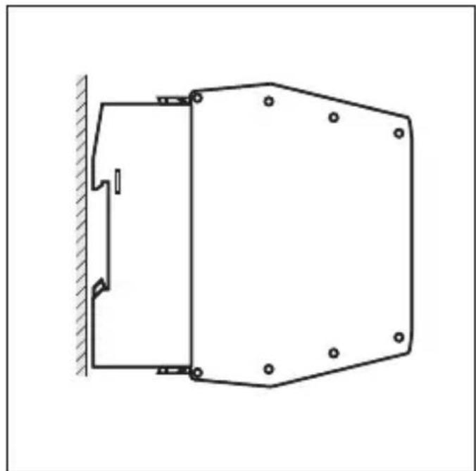
- Leave enough space ( ≥ 50mm ) between the device and the top and bottom of the control cabinet to enable air circulation and to avoid excessive heating.
6.3 Identical devices mounted side by side
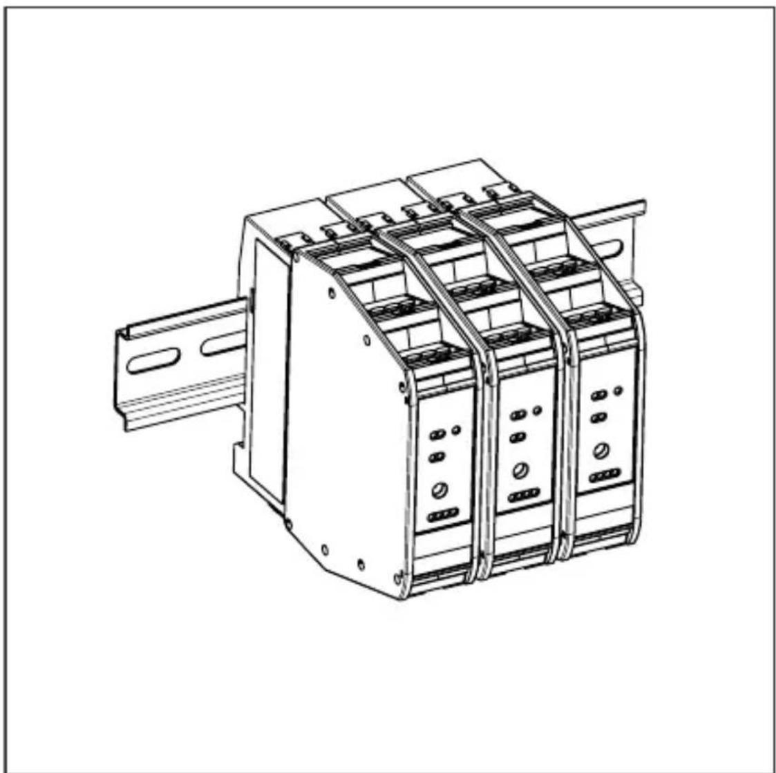
Fig. 1: Identical devices mounted side by side
6.4 Deratings for side by side mounting of identical devices
When identical units are mounted side by side with a minimum distance of 25mm , no deratings need to be observed.
When identical units are mounted side by side without any distance, derating according to the following table applies:
| Article number | Derating |
| AC009S Overall current rating of outputs when mounted side by side | |
| I [%] | |
| 100 | T [°C] |
| 90 | 01020304050607080 |
| 80 | Ambient temperature -25...50°C / linear derating 40...50°C |
| 70 | Overall current rating of outputs 50% each at 50°C corresponds to 2 x 3 A (example) |
| 60 | |
| 50 | |
| 40 | |
| 30 | |
| 20 | |
| 10 | |
6.5 Side by side mounting of different devices
| ATTENTION If units are mounted side by side, inadmissible heating may occur between the units. ► Malfunction / damage is possible. ► Take into account the internal heating of all devices when mounting different devices side by side and observe the environmental conditions for each device. |
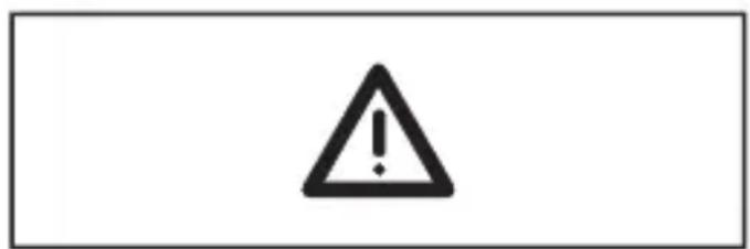
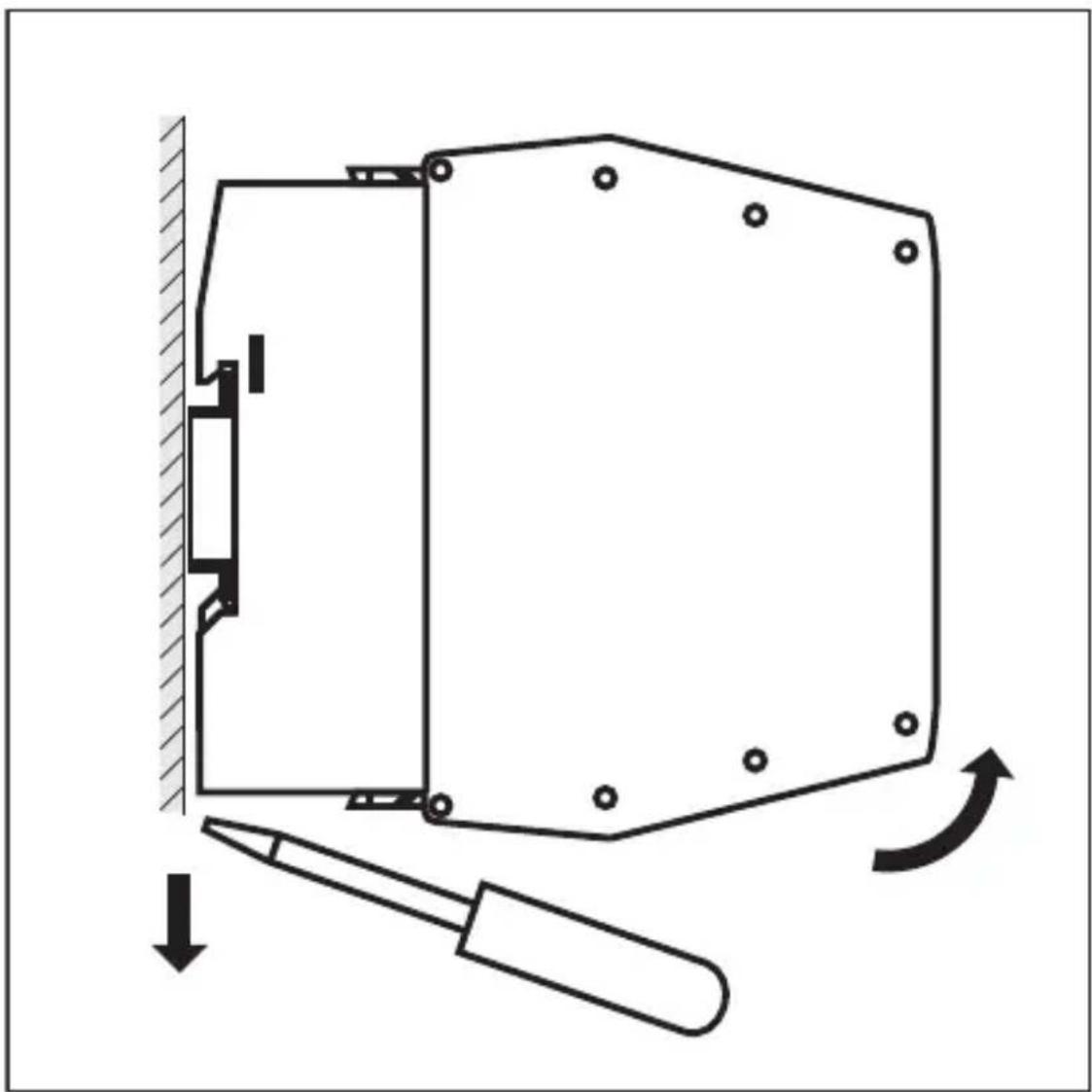
6.6 Removing the device
7 Electrical connection
7.1 General wiring information

The unit must be connected by a qualified electrician.
- Disconnect the device from the mains supply before installation; if necessary, also disconnect any independently supplied input / output load circuits.
Observe the national and international regulations for the installation of electrical equipment.
Voltage supply according to SELV, PELV.

Do not connect the inputs with external potential.

Please observe the required precautions against electrostatic discharge.

Connect the external switching contacts for the safe inputs to the screw terminals of the connectors.
Use switching contacts with:
a current rating ≥ 1 ampere
electrically isolated contact elements
contacts which open when there is a demand on the safety function
Cable length between module and mechanical contacts ≤ 10m
WARNING
Use of unconnected terminals.
Electric shock possible.
- Do not use unconnected terminals (n.c) which are not shown in the drawing as support point terminals.
Protection guaranteed.
Touchable surfaces of the device are insulated from the AS-i circuit and from the (non-safe) relay circuits O3 and O4 with basic insulation according to IEC 61010-1 (mains circuit of overvoltage category II up to 300V nominal mains voltage).
This does not apply to connection areas (IP 20).
The (non-safe) relay circuits O3 and O4 are insulated from AS-i with reinforced insulation according to IEC 61010-1 (mains circuit of overvoltage category II up to 300V nominal mains voltage).
The (non-safe) relay circuits O3 and O4 are insulated from each other with reinforced insulation according to IEC 61010-1 (mains circuit up to 300V of overvoltage category II).
The external wiring has to be carried out in a way that ensures the required separation from other circuits.
7.2 Safety instructions relay connections

The external protection of the relay currents according to the valid regulations to the values of the technical data is the responsibility of the system manufacturer.

The relays are not designed for small switching currents. If the relay outputs are used for switching very small currents (e.g. PLC inputs), considerable contact resistance can arise.

External interference suppression of inductive loads is required.
Connect only the same voltage sources to the relay connections O3 and O4 (e.g. 2 × 240 V AC, same line conductor or 2 × 24 V DC).

WARNING
Non-coded connectors.
The connectors for the operating voltage and of the O3, O4 relays can be mixed up during installation or device replacement.
Electric shock / dangerous voltage possible in the plant.
Check the position and correct connection of the connectors before commissioning.
Electrical safety is ensured.
7.3 Connection technology

ATTENTION
No IP 20 protection without connector.
Cover unused connectors with terminals.
Observe IP 20.
Strip the insulation from the connection cables to 10mm
7.4 Connection accessories
The device is supplied without connector.
7.5 Wiring
7.5.1 Terminal connection
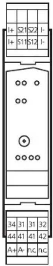
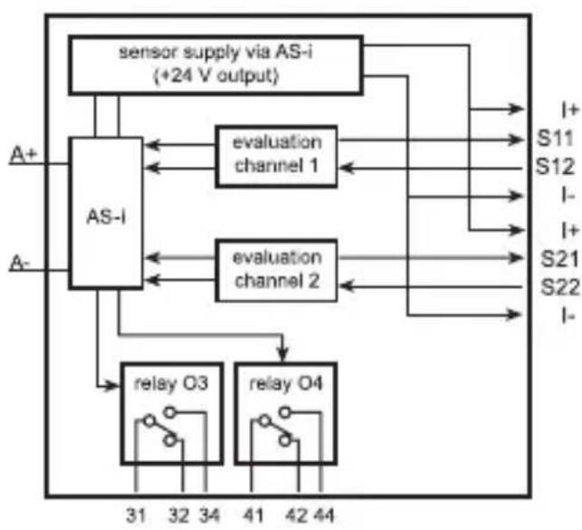
I+: sensor supply +24 V
I-: sensor supply 0 V
A+: AS-i +
A:-AS-i-
S11-S12/ switching input
S21-S22: mechanical contact SI1/SI2
sensor supply via AS-i
O3, O4: switching output relays O3, O4
31: relay O3 changeover contact, common
32: relay O3 changeover contact, normally closed
34: relay O3 changeover contact, normally open
41: relay O4 changeover contact, common
42: relay O4 changeover contact, normally closed
44: relay O4 changeover contact, normally open
n.c.: not used
The connected switching contacts must be configured as normally closed.
Connect two positively driven or two dependent switching contacts to the terminals S11-S12 and S21-S22 via a 4-wire cable.
The connection of two independent switching contacts is made to the terminals S11-S12 or to the terminals S21-S22 in separately laid cables.
7.6 Block diagram
8 Set-up
Switch on the supply voltage Technical data
Address safe AS-i module Address and project
Carry out function tests Operation
8.1 Addressing
When mounted and wired the module can be addressed with an addressing cable via the integrated addressing interface.
Assign a free address between 1 and 31, on delivery the address is 0.
9 Operation
Check the safe function of the unit. Display by LEDs:
| LEDs 1 LEDs 2 LEDs 3/4 | LEDs 1 yellow Inputs | switched |
| LED red ERROR Hardware fault / cross fault / short circuit | ||
| LED 2 green Voltage supply OK | ||
| LED 2 red lit AS-i communication error, slave does not participate in the "normal" exchange of data, e.g. slave address 0 | ||
| LED 2 red flashing Peripheral fault, e.g. overload or short circuit of the sensor supply | ||
| LED 3 red Alarm outputs O-1/O-2 (unsafe) (through the host system the alarm output LED can be set as a static or dynamic output) | ||
| LED 4 yellow Relay outputs O-3/O-4 (unsafe) | ||

Overload, cross fault and short circuit of the sensor supply are signalled to the AS-i master (version 2.1) via the "peripheral fault" flag in the status register.
10 Data bits
| Data bit D3 D2 D1 D0 | ||||
| In / Out SI-2 / O-4 | SI-2 / O-3 SI-1 / O-2 SI-1 / O-1 |
| Activated input channel Bit sequence D3-D0 | |
| SI-1 XX00 | |
| SI-2 00XX | |
| SI-1 and SI-2 0000 | |
| None XXXX | |
| Activated alarm outputs Bit sequence D3-D0 | |
| O-1 XXX1 | |
| O-2 XX1X | |
| Activated relay outputs Bit sequence D3-D0 | |
| O-3 X1XX | |
| O-4 1XXX | |
X = random
The code words 0000, XX00 and 00XX cause the AS-i safety monitor to bring the installation into the safe state.
For more details on the effect of the data bits on the transmission sequence refer to the configuration software manual (see the chapter "Monitoring devices").

Note: non-safe relay outputs
Do not use the non-safe relay outputs for safety-related functions.
11 Response times
The response time of the safe AS-i module for a safety demand is max. 10 ms. Calculation of the total response time:
For the calculation of the response time of the complete system the response times of the other components also have to be added (mechanical contacts, safety monitor and external relays or contactors possibly connected to the safety monitor output).

If only one single-channel switch is to be connected to the module, it is to be connected to the input S11-S12. The second input S21-S22 must be bridged. This can be done by means of a wire link between the terminals S21 - S22.

Note: The wiring influences the achievable control category.
The requirements for external wiring and the selection of the connected switching contacts refer to the functionality to be accomplished and to the required performance level (EN ISO 13849-1 or IEC 61508).
The performance level is either determined by means of a risk analysis (e.g. to EN ISO 14121) or taken from a C standard. The performance level or SIL of the AS-i safety monitor must at least correspond to the performance level or SIL required by the application.
12 Technical data
| Application area | |
| Electrical design 2 safe inputs/ | 2 non-safe LED outputs 2 non-safe relay outputs |
| Application Control cabinet installation | |
| Electrical data | |
| Operating voltage 26.5....31.6 V DC | |
| Max. current consumption from AS-i 250 mA | |
| Integrated watchdog Yes | |
| Inputs / outputs | |
| Number of inputs and outputs Number of digital inputs: 2 Number of digital outputs: 2 Number of relay outputs: 2 | |
| Inputs | |
| Number of safe inputs 2 | |
| Circuits DC PNP | |
| Sensor supply of inputs AS-i | |
| Overall current rating of inputs 100 mA | |
| Input current typ. 10 mA | |
| Short-circuit detection Yes | |
| Cross fault monitoring Yes | |
| Outputs | |
| LED output | |
| Number of digital outputs 2 | |
| Relay outputs | |
| Number of relay outputs 2 | |
| DC voltage range 24 V | outputs O3 and O4 must be supplied with the same voltage 2x24 V DC) |
| AC voltage range 10...240 V | (outputs O3 and O4 must be supplied with the same voltage 2x240 V AC) |
| Current rating per output 6 A (resistive load) | |
| Overall current rating of outputs 6 A (resistive load) | |
| Short-circuit protection No | |
| Electrically isolated Yes | |
| Environmental conditions | |
| Ambient temperature -25....50 °C | |
| Storage temperature -25....80 °C | |
| Max. relative air humidity < 80%, no condensation permitted | |
| Max. height above sea level 2000 m | |
| Protection rating IP 20 | |
| Operating mode Protective operation | |
| Degree of soiling 2 | |
| AS-i classification | |
| AS-i version 2.11 / 3.0 | |
| Extended addressing mode No | |
| AS-i profile S-7.B.E | |
| AS-i I/O configuration [hex] 7 | |
| AS-i ID code [hex] | B.E |
| AS-i certificate | 62001 |
| Mechanical data | |
| Housing materials | PA |
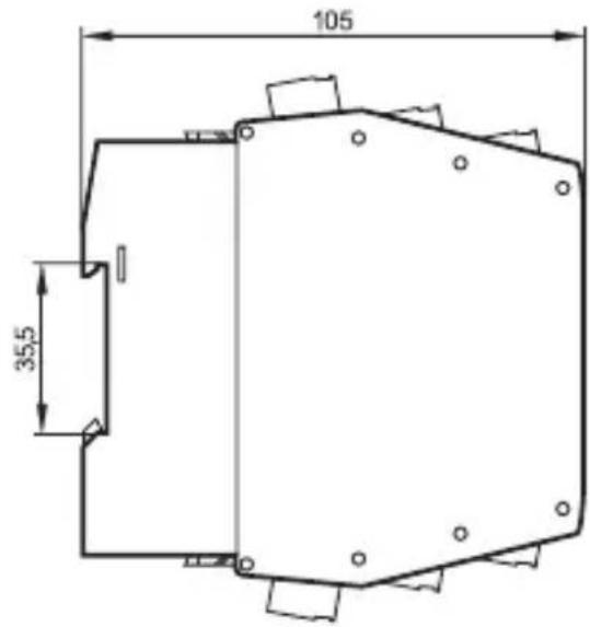
| Dimensions [mm] 114 x 25 x 105 (H x W x D) | |
| Display / operating elements | |
| Switching status indication | LED yellow I1...I2, O3...O4 |
| Operation indication | LED green AS-i |
| Fault indication | LED red ERR, O1...O2 |
13 Safety characteristics
| Meets the requirements of EN ISO 13849-1: 2015 category 4 PL e IEC 61508: 2010 SIL 3 | |
| Mission Time (TM) 20 years | |
| PFH 4 x 10 | -9/h |
These calculations were made on the basis of an ambient temperature of 40^ . They are only valid for two-channel applications.
The device complies with the requirements of EN ISO 13849-1: 2015 category 4 PL e, SIL 3 (IEC 61508) and can be used in applications up to SIL 3 / PL e.
The PFH values of the other components, especially of the AS-i safety monitor, can be found in the corresponding documentation.
Explanation of the abbreviations
| SIL Safety Integrity Level Safety Integrity Level SIL 1-4 to IEC 61508. The higher the SIL, the lower the probability that a safety function will fail. |
| PL Performance level Capability of safety-related parts to perform a safety function under predictable conditions to fulfil the expected risk reduction. |
| PFH Probability of dangerous failure per hour Probability of a dangerous failure per hour. |
| Cat. Category Category |
| T Life time Max. service life |
14 Scale drawing
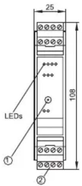
1: Addressing socket
2: Connector with screw terminals (option)
15 Troubleshooting
The LEDs of the safe AS-i control cabinet module indicate faulty operating states (→Operation).
16 Maintenance, repair and disposal
The operation of the unit is maintenance-free.
Only the manufacturer is allowed to repair the unit.
After use dispose of the device in an environmentally friendly way in accordance with the applicable national regulations.
Cleaning the unit:
Disconnect the unit from the voltage supply.
Clean the unit from dirt using a soft, chemically untreated and dry micro-fibre cloth.
Contenu
- ESE\$panol
- Preliminary note
- Symbols used
- 1.2Warnings used
- Safety instructions
- Intended use
- Safety-related requirements
- Safety symbol on the device
- IT safety
- Items supplied
- Function description
- Installation
- Installation location
- Installation of the device
- Identical devices mounted side by side
- Deratings for side by side mounting of identical devices
- Side by side mounting of different devices
- Removing the device
- Electrical connection
- General wiring information
- WARNING
- Safety instructions relay connections
- Connection technology
- ATTENTION
- Connection accessories
- Wiring
- Terminal connection
- Block diagram
- Set-up
- Addressing
- Operation
- Data bits
- Response times
- Technical data
- Safety characteristics
- Scale drawing
- Troubleshooting
- Maintenance, repair and disposal
- Contenu
Brand : IFM
Model : AC009S
Category : Electronic module