
AC007A - Electronic module IFM - Free user manual and instructions
Find the device manual for free AC007A IFM in PDF.
| Product type | AS-i slave module |
| Brand | IFM |
| Model | AC007A |
| AS-interface version | 2.1 |
| AS-i supply voltage | 26.5 … 31.6 V DC |
| Current consumption | < 150 mA |
| External actuator supply | 24 V DC (15 … 30 V DC) according to TBTP |
| Total output current (inputs) | 100 mA |
| Current per output (DC13) | 1 A typ., max. 2 A per module |
| Max number of modules per master | 31 |
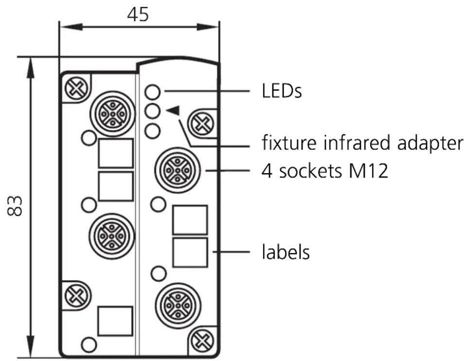
| Sensor connections | 2 M12 sockets (5-pin) |
| Actuator connections | 2 M12 sockets (5-pin) |
| LED indicator 1 (yellow) | Status of switched inputs/outputs |
| LED indicator 2 (green) | Supply voltage OK |
| LED indicator 3 (red continuous) | AS-i communication error |
| LED indicator 4 (red flashing) | Peripheral fault (sensor overload/short circuit) |
| LED indicator 5 (IR receiver) | Infrared addressing active |
| Addressing | Via AC1144 unit or infrared |
| Dimensions (estimated) | 100 x 50 x 30 mm |
| Weight (estimated) | 50 g |
| Main functions | Connection of 2 sensors (2-wire or PNP) and 2 actuators to AS-i network |
| Maintenance and cleaning | Clean with a dry cloth, avoid harsh chemicals |
| Safety | Respect TBTP for external supply, do not exceed max currents |
| Spare parts and repairability | No replaceable parts, repair by qualified professional |
| General information | Indoor use; operating temperature 0…60°C (estimated) |
Frequently Asked Questions - AC007A IFM
User questions about AC007A IFM
0 question about this device. Answer the ones you know or ask your own.
Ask a new question about this device
Download the instructions for your Electronic module in PDF format for free! Find your manual AC007A - IFM and take your electronic device back in hand. On this page are published all the documents necessary for the use of your device. AC007A by IFM.
USER MANUAL AC007A IFM
Function and features
- The AS-i module operates as a slave in the AS-i network (AS-i profile: S-3.0.E). It connects two sensors (2-wire sensors or PNP 3-wire sensors) and two actuators (15 ... 30 V DC) with the AS-i master.
- AS-interface version 2.1
- Operating voltage 26.5 ... 31.6V
- Current consumption < 150mA
- Max. current load for all inputs total 100mA
- External power supply to PELV
Voltage range 24V DC (15...30V DC) -
Max. current load per output (DC13)* 1A (typ.), max. 2A per module
-
Utilisation category (DC13): The switch-on and switch-off capacity for the triggering of solenoids is rated up to 20W (to IEC 947-5-2).
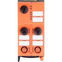
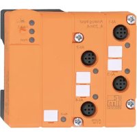
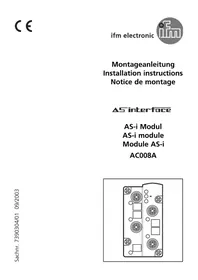
Operating and display elements
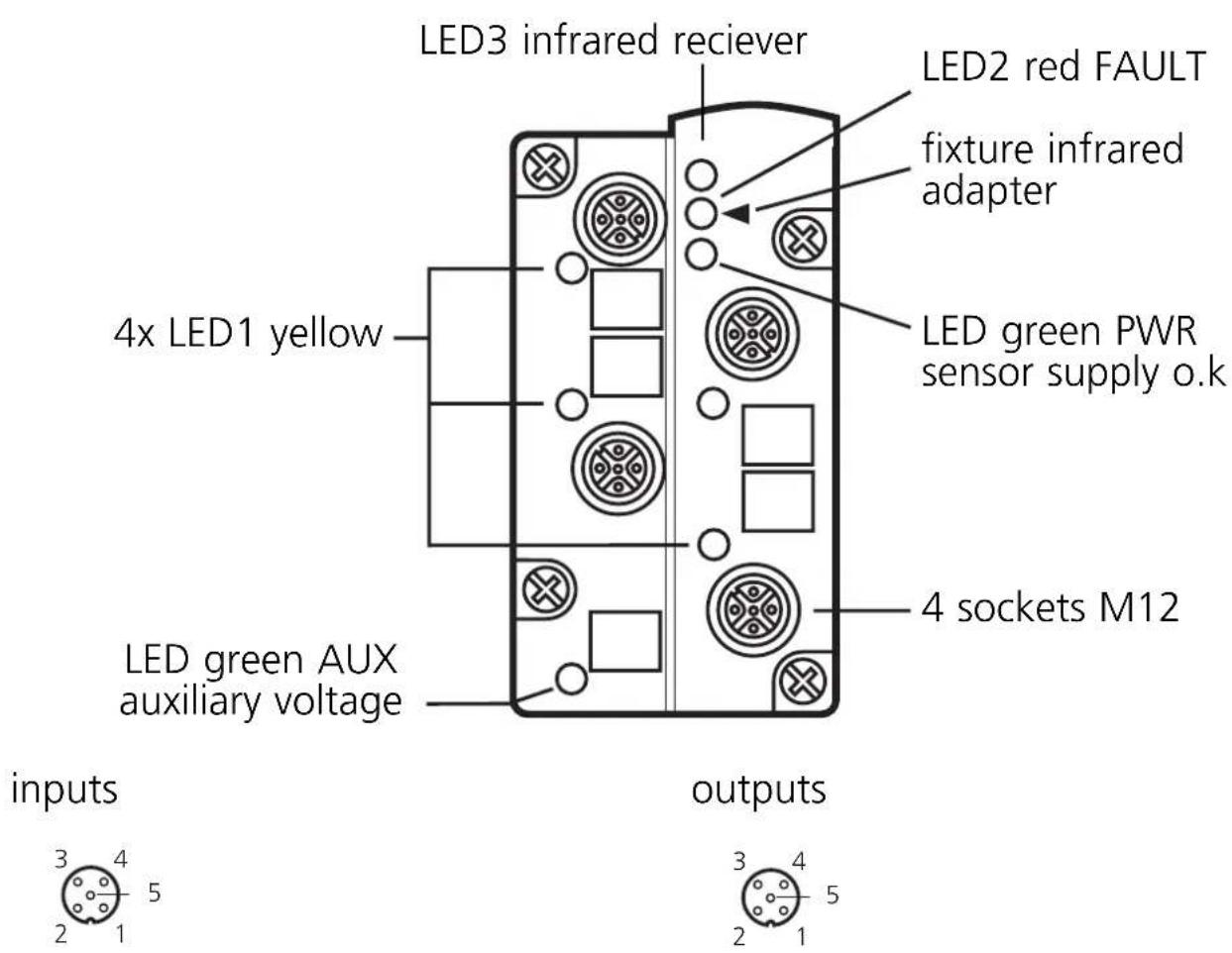
| socket M12 pin | |
| sensor supply L+ | 1 |
| sensor supply L- 3 | |
| data input 2+4 | |
| not connected 5 |
| socket M12 pin | |
| switching output + | 4 |
| external voltage - 3 | |
| not connected 1,2,5 | |
Addressing
Assign a free address between 1 and 31. At the factory the address is set to 0.
Addressing with the adressing unit AC1144
If it is used with the FC-E lower part without addressing socket the module must first be addressed via the addressing unit AC1144 and then mounted onto the lower part.
Infrared addressing
The AS-i module also offers the option of infrared addressing with the addressing unit AC1144.
The AS-i communication (yellow cable) must be switched off during the infrared addressing.
Supply the slaves with voltage via the AS-i power supply. Addressing is carried out via the IR addressing cable E70211.
When the ifm AS-i power supplies type SL are used the communication can be deactivated via a plug on the power supply. To do so, disconnect the master.
Operation
Check the reliable functioning of the unit. Display by LEDs:
- LED 1 yellow: input /output switched
- LED green: voltage supply o.k.
- LED 2 red is lit: AS-i communication error, slave does not participate in the "normal" data exchange, e. g. slave address 0
- LED 2 red flashing: peripheral fault, e.g. overload or short circuit of the sensor supply
- LED 3: infrared reciever
Overload and short circuit of the input supply are signalled to the AS-i master (version 2.1) via the "peripheral fault" flag in the status register.
Brand : IFM
Model : AC007A
Category : Electronic module