USER MANUAL AC2566 IFM
natural_image
Top-down schematic of a room layout with labeled compartments and fixtures (no text or symbols)
text_image
3
4
5
2
1
analog in
Strom
U+
text_image
3
4
5
1
2
analog in
Strom
U+
U-
text_image
3
4
5
1
2
analog in
analog -
U+
U-

text_image
3
4
5
2
1
U+
U-
Function and features
The slave converts analogue input signals and transfers them to the AS-i master via the AS-Interface. The AS-i module operates as a slave with bidirectional data transfer in the AS-i network.
The data transfer to the host is asynchronous according to the AS-i profile S-7.3 and the AS-i specification V2.1.
- Sensor supply from AS-i (max. 100 mA) or external 24 V PELV voltage source (black flat cable, max. 500 mA)
- Resolution: 1 A (AC2516, AC2566) or 1 mV (AC2517)
- special features AC2566: stainless steel screws, Viton sealing
Installation / Addressing
When you use module lower parts without addressing socket (AC5000 or AC5003) first address the module by placing it onto an addressing unit (AC1144) and assign a free address between 1 and 31.
When you use module lower parts with an addressing socket (AC5010 or AC5011) the modules can be addressed with the addressing adapter E70213 later on.
Mount the module onto the wired module lower part of the AS-i network, tightening torque 0.8 Nm.
As an alternative FC/FC-E lower parts with earthing lead (AC5020...AC5023) can be used to increase the noise immunity.
text_image
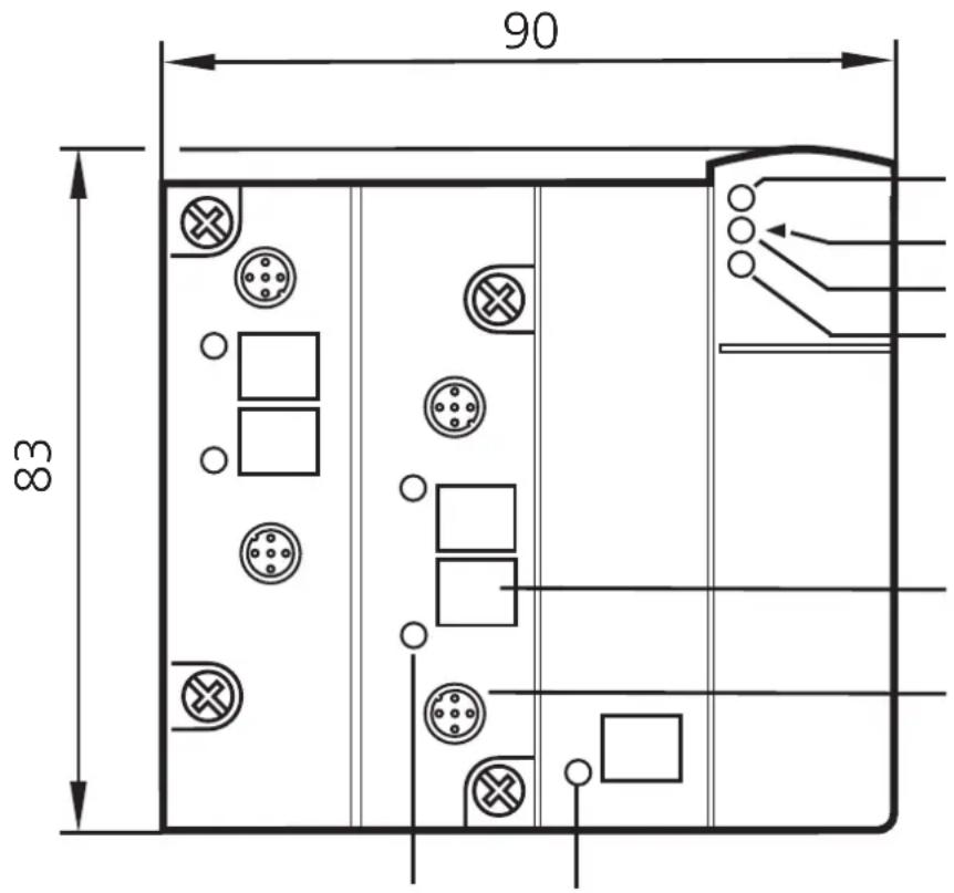
90
83
4x LED yellow analogue inputs
LED infrared receiver
fixture infrared adapter
LED red FAULT
LED green PWR
label
M12 socket
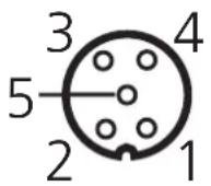
Pin 1: sensor supply +24 V
Pin 2: Al+ analogue input
Pin 3: sensor supply 0 V
Pin 4: Al- analogue input 0 V
Pin 5: functional earth
Electrical connection
The analogue module is connected to the AS-Interface via the standardised EMS (supply from AS-i) or the E-EMS (supply from an ext. 24 V PELV voltage source).
If the supply is to be from an external 24 V source, a FC-E lower part (art. no. AC5003 or AC5011) must be used.

If a total of over 100 mA is needed for the sensor supply, the supply must be from an external 24 V PELV voltage source.
The supply is automatically changed when the external 24 V voltage is supplied.

Risk of destruction:
When a combined sensor (pin 2: analogue output, pin 4: 24 V output) is connected ensure that the switching output cannot switch. To do so, set the combined sensor accordingly (e.g. by selection of a switch point which cannot be reached or by the configuration "NPN switching").
Current measurement AC2516, AC2566
For all the following wiring diagrams the indicated pin connection refers to the analogue module.
When an external link between pin 3 and pin 4 is used, the internal link can be deactivated by resetting the parameter bit PO!

The internal link (pin 3 and pin 4) must be activated via the parameter bit P0.
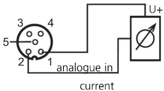
Connection of a 2-wire sensor without own supply
Pin 1: sensor supply +24 V
Pin 2: Al+ analogue input
Pin 3: sensor supply 0 V
Pin 4: AI- analogue input 0 V
Pin 5: functional earth
text_image
3
4
5
2
1
analogue in
current
U+
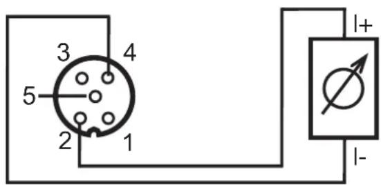
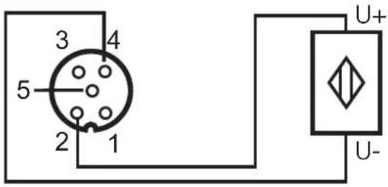
Connection of a 2-wire sensor with own supply
Pin 1: sensor supply +24 V
Pin 2: Al+ analogue input
Pin 3: sensor supply 0 V
Pin 4: AI- analogue input 0 V
Pin 5: functional earth
text_image
3
4
5
2
1
I+
I-
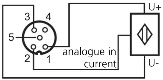
Connection of a 3-wire sensor without own supply
Pin 1: sensor supply +24 V
Pin 2: Al+ analogue input
Pin 3: sensor supply 0 V
Pin 4: Al- analogue input 0 V
Pin 5: functional earth
text_image
3
4
5
1
2
U+
analogue in
current
U-
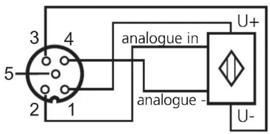
Connection of a 4-wire sensor without own supply
Pin 1: sensor supply +24 V
Pin 2: Al+ analogue input
Pin 3: sensor supply 0 V
Pin 4: AI- analogue input 0 V
Pin 5: functional earth
text_image
3
4
5
1
2
analogue in
U+
analogue -
U-

When a 4-wire sensor is connected the internal link between pin 3 and pin 4 must be deactivated by resetting the parameter bit P0.
Voltage measurement AC2517

The parameter bit P0 is of no importance for the AC2517!
Connection of a 2-wire sensor without own supply
Pin 1: sensor supply +24 V
Pin 2: Al+ analogue input
Pin 3: sensor supply 0 V
Pin 4: Al- analogue input 0 V
Pin 5: functional earth
text_image
3
4
5
2
1
U+
U-
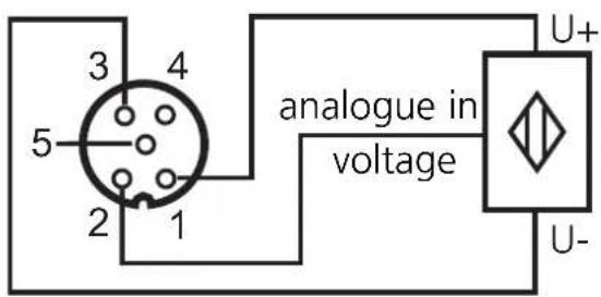
Connection of a 3-wire sensor without own supply
Pin 1: sensor supply +24 V
Pin 2: Al+ analogue input
Pin 3: sensor supply 0 V
Pin 4: AI- analogue input 0 V
Pin 5: functional earth
text_image
3
4
5
1
2
U+
analogue in
voltage
U-

When a 3-wire sensor without own supply is connected the link between pin 3 and pin 4 has to be created externally!
Parameter setting of the analogue modules
| Parameter bit | Designation | Description |
| P0(not used for AC2517) | selection2/3 wires / 4 wires | 1 | 2-/ 3-wire operation (link active) |
| 0 | 4-wire operation (link inactive) |
| P1, P2 | channel activation | P1 | P2 | channel1 | channel2 | channel3 | channel4 |
| 0 | 0 | on | off | off | off |
| 0 | 1 | on | on | off | off |
| 1 | 0 | on | on | on | off |
| 1 | 1 | on | on | on | on |
| P3 | periphery fault | 1 | periphery fault indication active |
| 0 | periphery fault indication not active |
Operation AC2516, AC2566
Check whether the unit operates correctly. Display by LEDs:
• LEDs yellow Al-1...Al-4 on: analogue signal in the measuring range
- LEDs yellow AI-1...AI-4 flashing: analogue signal outside the measuring range, no sensor connected or wire break
- LEDs yellow Al-2...Al-4 out: no sensor connected (at least one LED flashes because not all channels can be deactivated via the parameter bit P1/P2 (channel activation, channel 1 is always activated)
• LED green PWR on: AS-i voltage applied
• LED green AUX on: external 24 V voltage applied
- LED red FAULT on:
AS-i communication error, e.g. slave address 0
- LED red FAULT flashes: periphery fault*
* Periphery fault
A periphery fault is displayed:
- if at least one of the analogue signals is outside the value range
- if nothing is connected to at least one analogue channel although the respective channel is activated
- if a wire break occurred
Operation AC2517
Check whether the unit operates correctly. Display by LEDs:
- LEDs yellow Al-1...Al-4 on: respective channel is activated analogue signal in the measuring range or no sensor connected (it cannot be differentiated whether the 0 V signal is applied or whether no sensor is connected) (channel 1 is always activated)
• LEDs yellow Al-1...Al-4 flashing: analogue signal outside the measuring range (outside range)
• LEDs yellow Al-2...Al-4 out: respective channel is not activated
• LED green PWR on: AS-i voltage applied
• LED green AUX on: external 24 V voltage applied
- LED red FAULT on:
AS-i communication error, e.g. slave address 0
- LED red FAULT flashes: periphery fault*
* Periphery fault
A periphery fault is displayed:
- if at least one of the analogue signals is outside the value range
The measuring ranges, the states of the LEDs and their meaning are indicated in the following tables:
Analogue input module 4 ... 20 mA - AC2516, AC2566
| Range4 ... 20mA | Unitsdec. | Unitshex. | LED AI1...AI4 analogue | Meaning |
| < 1 mA 327 | 67 7FFF flashes wire break | | |
| 1 mA ...3.999 mA | 1000 ... 3999 | 3E8 ... 0F9F on below nominal | low nominal | range |
| 4 mA ...20 mA | 4000 ... 20000 | 0FA0 ... 4E20 on nominal range |
| 20.001 mA ...23 mA | 20001 ... 23000 | 4E21 ... 59D8 | on | above nominal range |
| > 23 mA | 32767 | 7FFF | flashes | outside range |
Analogue input module 0 ... 10 V - AC2517
| Range0 ... 10 V | Unitsdec. | Unitshex. | LED analogue | Meaning |
| 0 ... 10 V 0000 | 0 ... 10000 0000 | ... 2710 on nominal range | |
| 10.001 V ... 11.5 V | 10001 ... 11500 | 2711 ... 2CEC on | above nominal | range |
| > 11.5 V | 32767 | 7FFF | flashes | outside range |
Transmission time of the analogue values
The transmission time of the analogue values depends on the conversion time of the analogue signals into digital signals in the AS-i module and on the transmission time via the AS-Interface.
Example: Transmission time of 2 analogue channels
The conversion time for 2 analogue input signals into digital signals is 120 ms. The transmission time of the 2 16-bit values via the AS-interface ideally is 7 AS-i cycles per value. For a cycle time of 5 ms per ASi cycle this results in a transmission time of 2 × 7 × 5 ms = 70 ms via the AS-Interface.
Thus the total transmission time for 2 analogue values ideally is 120 ms (conversion time) + 70 ms (transmission time) = 190 ms.
Example: Transmission time of 4 analogue channels
The conversion time for 4 analogue input signals into digital signals is 240 ms. The transmission time of the 4 16-bit values via the AS-interface ideally is 7 AS-i cycles per value. For a cycle time of 5 ms per AS-i cycle this results in a transmission time of 4 × 7 × 5 ~ms = 140 ~ms via the AS-Interface.
Thus the total transmission time for 4 analogue values ideally is 240 ms (conversion time) + 140 ms (transmission time) = 380 ms.
text_image
3
4
5
2
1
U+
U-