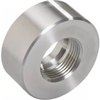
E30009 - Welding fitting IFM - Free user manual and instructions
Find the device manual for free E30009 IFM in PDF.


User questions about E30009 IFM
0 question about this device. Answer the ones you know or ask your own.
Ask a new question about this device
Download the instructions for your Welding fitting in PDF format for free! Find your manual E30009 - IFM and take your electronic device back in hand. On this page are published all the documents necessary for the use of your device. E30009 by IFM.
USER MANUAL E30009 IFM
Operating instructions Welding adapter
Contents
1 Preliminary note 3
1.1 Symbols used 3
1.2 Warnings.... 3
2 Safety instructions.... 4
3 Intended use.... 5
3.1 Basic notes 5
4 Installation.... 6
4.1 Welding operation with welding aid 6
5 Set-up 8
6 Disposal and return.... 9
1 Preliminary note
You will find instructions, technical data, approvals and further information using the QR code on the unit / packaging or at documentation.ifm.com.
1.1 Symbols used
√ Requirement
Instructions
Reaction, result
[...] Designation of keys, buttons or indications
→ Cross-reference

Important note
Non-compliance may result in malfunction or interference.

Information
Supplementary note
1.2 Warnings
Warnings indicate the possibility of personal injury and damage to property. This enables safe product handling. Warnings are graded as follows:

WARNING
Warning of serious personal injury
▷ If the warning is not observed, fatal and serious injuries are possible.

CAUTION
Warning of minor to moderate personal injury
▷ If the warning is not observed, minor to moderate injuries are possible.
ATTENTION
Warning of damage to property
▷ If the warning is not observed, damage to property is possible.
2 Safety instructions
- The unit described is a subcomponent for integration into a system.
- The system architect is responsible for the safety of the system.
-
The system architect undertakes to perform a risk assessment and to create documentation in accordance with legal and normative requirements to be provided to the operator and user of the system. This documentation must contain all necessary information and safety instructions for the operator, the user and, if applicable, for any service personnel authorised by the architect of the system.
-
Read this document before setting up the product and keep it during the entire service life.
- The product must be suitable for the corresponding applications and environmental conditions without any restrictions.
- Only use the product for its intended purpose (→ Intended use).
- Only use the product for permissible media (→ Technical data).
- If the operating instructions or the technical data are not adhered to, personal injury and/or damage to property may occur.
- The manufacturer assumes no liability or warranty for any consequences caused by tampering with the product or incorrect use by the operator.
- Installation, set-up, operation and maintenance of the product must be carried out by qualified personnel authorised by the machine operator.
- The welding operation must be carried out by authorised personnel.
- The welding operation must be carried out carefully and according to state-of-the-art technology.
- During the welding process, ensure sufficient fume extraction.
- Protect the product against damage.
3 Intended use
The welding adapter allows the installation of sensors in tanks or piping systems.
3.1 Basic notes
If the tank or pipe system is treated after the adapter has been welded in (e.g. grinding, pickling, sand-blasting, glass bead blasting or applying procedures such as powder coating, painting etc.):
▶ Make sure that the inside and sealing area of the adapter are clean and not damaged. Appropriate measure: → using the welding aid.
The welding operation must be carried out by authorised personnel.
The welding operation must be carried out carefully and according to state-of-the-art technology.
During welding and the following cooling phase the sensor must not be in place.
The surfaces must be free from any contamination.
Welding materials must be suitable for the adapter and wall material.
▶ The requirements in the specifications, of common practice, in regulations, standards, of intended use and the application must be applied.
▷ They determine the welding procedure, the welding material, the connection category and connection type, including chamfer, welding penetration depth and demands on the surface.
4 Installation

CAUTION
During the welding operation, the adapter, the surrounding material and any welding aid used can increase in temperature to over 65\ °C ( 149\ °F ).
▷ Risk of burns.
▶ Allow the adapter and any other components to cool.
4.1 Welding operation with welding aid

The basic notes and guidelines must be adhered to: Basic notes ( → ☐ 5)
▶ The welding method must be suitable for the welding task and the power of the welding equipment must be adapted to the material thickness.
▶ While welding, the adapter must not warp.
▶ During welding, avoid overheating of the adapter and observe sufficient cooling phases.
▶ The sealing area of the adapter must not be damaged by weld spatter or similar. The sealing area should be sufficiently protected before starting the welding process.
▶ Bore a hole in the pipe or tank wall with the outside diameter of the adapter.
▶ Insert a welding aid for heat conduction and protection of the sealing area: order no. E30435 for G1 thread, order no. E30071 for G 3/4 thread.
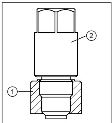
Welding adapter (1) with mounted welding aid (2).
▶ Adapter alignment: turn the marking to the position provided for the connector / display of the screwed sensor.

A: groove for O-ring (for E30072), B: position marking for alignment

Please take into account the required space when using a connection cable with an angled socket. For this purpose, align the adapter prior to the welding operation to determine the end position of the electrical sensor connection.

The positioning may change when the sensor is removed and then the original orientation is not guaranteed.
▶ Fix the adapter in several spots with a sufficient adhesive force. Apply the fixing points at equal distance opposite each other.
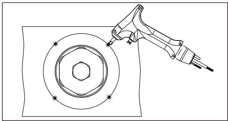
▶ Apply the welding seams between the fixing points opposite each other.
▶ Ensure sufficient intervals between the individual sections to avoid glowing through or warping of the adapter due to overheating.
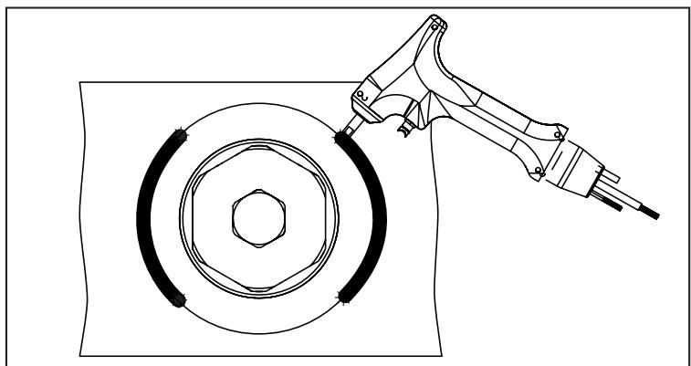
▶ If possible: weld the inside.

▶ Let the adapter and the welding aid cool down.
▶ Remove the welding aid.
▶ Remove deposits from the adapter thread.
▶ Screw in the sensor by hand in order to check for dimensional accuracy and functionality of the thread. If the tightening torque is too high, do not use any tool, but check the thread and replace the adapter, if necessary.
5 Set-up
▶ Before setting up the system: Check all components for ingress resistance.
Setting up the sensor: → Operating instructions of the sensor.
6 Disposal and return
▶ After use, dispose of the unit in an environmentally friendly way in accordance with the applicable national regulations.
▶ In case of return shipment, ensure that the unit is free from soiling, especially from dangerous and toxic substances.
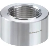
Brand : IFM
Model : E30009
Category : Welding fitting