WS5400 - Weather Station ALECTO - Free user manual and instructions
Find the device manual for free WS5400 ALECTO in PDF.
| Product Type | 7-in-1 weather station with Wi-Fi module |
| Brand | Alecto |
| Model | WS5400 |
| Indoor console dimensions | 130 x 112 x 27.5 mm |
| Indoor console weight | 220 g (with batteries) |
| Indoor console power supply | 5 V DC 1 A adapter + CR2032 backup battery |
| Outdoor unit dimensions | 343.5 x 393.5 x 136 mm (mounted) |
| Outdoor unit weight | 757 g (with batteries) |
| Outdoor unit power supply | 3 AA 1.5 V batteries (Lithium recommended) |
| RF transmission frequency | 868 MHz |
| Transmission range | Up to 150 m in open field |
| Indoor temperature range | -5°C to 50°C |
| Indoor humidity range | 10 to 90% RH |
| Outdoor temperature range | -40°C to 60°C |
| Outdoor humidity range | 1 to 99% RH |
| Main functions | Temperature, humidity, barometric pressure, wind speed and direction, rainfall, UV, light intensity, weather forecast, clock, alarm, Wi-Fi (Smartlife) |
| Connectivity | Wi-Fi 2.4 GHz, Smart Life/Tuya app |
| Display | LCD with backlight |
| Maintenance and cleaning | Clean the rain gauge every 3 months, replace batteries about once a year, clean the UV sensor with a soft cloth |
| Safety | Respect battery polarity, do not expose to water, use only the supplied adapter |
| Spare parts and repairability | Replaceable batteries, removable anemometer cup and wind vane, detachable rain collector, removable radiation shield |
| General information | 7-in-1 weather station with outdoor sensors and indoor console, compatible with Smart Life platform for IoT |
Frequently Asked Questions - WS5400 ALECTO
User questions about WS5400 ALECTO
0 question about this device. Answer the ones you know or ask your own.
Ask a new question about this device
Download the instructions for your Weather Station in PDF format for free! Find your manual WS5400 - ALECTO and take your electronic device back in hand. On this page are published all the documents necessary for the use of your device. WS5400 by ALECTO.
USER MANUAL WS5400 ALECTO
text_image
Labeled diagram of a device rear panel with numbered components and portstext_image
Technical diagram of a mechanical device with numbered parts, including internal components and cross-sectional views.3. INSTALLATIE VAN DE WS5400
VOORBEREIDENDE CONTROLE
text_image
Technical diagram showing a mechanical component with labeled pins and a zoomed-in view of the internal structure.DE INSTALLATIEMAST INSTALLEREN
natural_image
Technical diagram of a mechanical assembly with an inset showing a close-up of a component (no text or symbols present)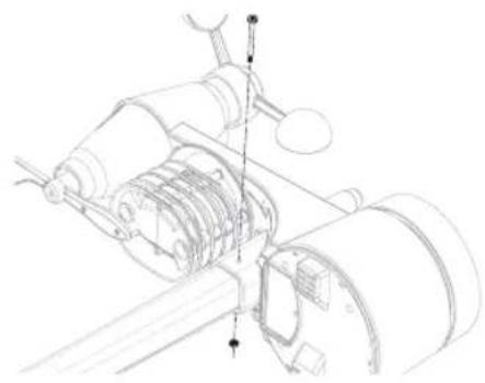
natural_image
Technical line drawing of a mechanical assembly with gears and shafts (no text or symbols)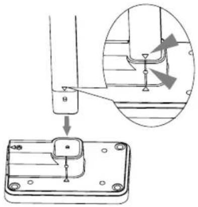
text_image
Technical diagram showing a mechanical assembly with an inset close-up of a component detail and a labeled component with arrows.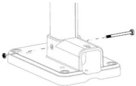
natural_image
Technical line drawing of a mechanical bracket with mounting holes and a screw (no text or symbols)text_image
Technical diagram showing mechanical assembly with labeled components and a magnified inset view of a cylindrical component.natural_image
Technical line drawing of a device rear panel with a cable inserted, showing no text or symbolsflowchart
Smart home system development flowchart covering sensor selection, weather management, device reset, and monitoring steps with Chinese annotations.SCHERMOVERZICHT VAN SMARTLIFE WS5400
flowchart
graph TD
    A["Overcast"] --> B["All Devices"]
    B --> C["Smart 7-in-1 weather station"]
    C --> D["35°C Outdoor Tem..."]
    D --> E["Excellent Outdoor PM2.5"]
    E --> F["Quality Outdoor Air G..."]
    F --> G["If "Tem perature...""]
    G --> H["All Devices"]
    H --> I["Smart 7-in-1 Wea..."]
    I --> J["Create Smart"]
    J --> K["Set a condition"]
    K --> L["Launch Tap-to-Run"]
    K --> M["When weather changes"]
    K --> N["Schedule"]
    K --> O["When device status changes"]

natural_image
Line drawing of a mechanical tool or plunger (no text or symbols present)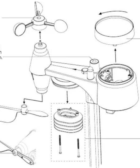
text_image
Technical diagram of a weather instrument with labeled parts including fan, propeller, and housing componentsDE REGENVANGER REINIGEN
DE HYGRO-/THERMOSENSOR REINIGEN
- INTRODUCTION......25
- PRODUCT OVERVIEW 26
- INSTALLATION OF THE WS5400 27
- WORKING WITH THE SMARTLIFE APP .... 31
- UPDATING THE WS5400 (FIRMWARE) 36
- SETTINGS & FUNCTIONS OF THE CONSOLE....36
- MAINTENANCE ....42
- SPECIFICATIONS ......43
ABOUT THIS USER'S MANUAL

This symbol represents a warning. To ensure safe use, always adhere to the instructions described in this documentation.

This symbol is followed by a user's tip.
1. INTRODUCTION
Thank you for choosing the Alecto WS5400, 7 in 1 Weather station.
The WS5400 has a Wi-Fi module and is compatible with the Smartlife platform.
The outdoor unit is a 7 in 1 station capturing temperature, humidity, wind speed, wind direction, rain, UV radiation and light intensity. The measurement data from the sensors is transmitted to the display unit.
Through the Smartlife app you can monitor the weather data collected by the indoor and outdoor unit. The Smartlife platform enables the WS5400 to connect with thousands of other smart products and trigger scenario's based on real time data.
The indoor unit receives the measured data from the outdoor unit and also includes its own temperature sensor, humidity sensor and pressure sensor. The measured data is displayed in a clear and orderly way.
Note:
This instruction manual contains useful information on the proper use and care of this product. Please read this manual through to fully understand and enjoy its features, and keep it handy for future use.
2. PRODUCT OVERVIEW
DISPLAY
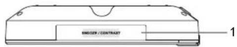
text_image
ENSOX/CONTRACT 1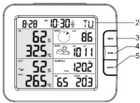
text_image
8:28 10:30 TU 62% 325°C OUT 52% 265°C WIND 86 RADD 1011 RUNPALL 1202 UN 65 203 2 3 4 5 BARD
text_image
Labeled diagram of a device rear panel with numbered components and ports- SNOOZE/CONTRAST key
- LCD display
- MEM key
- RAIN key
- BARO key
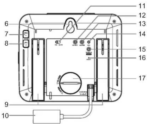
- Wall mounting hole
- WIND / + key
- NDX / - key
- Table stand
- Time & Date
- Indoor / temperature & humidity
- Outdoor temperature & humidity
-
WIND, BARO, RAIN, UV and Light intensity
-
Power jack
- ON / AUTO slide switch
- CH / SET key
- ALARM key
- CAL key
- SENSOR / Wi-Fi key
- RESET key
- Battery door
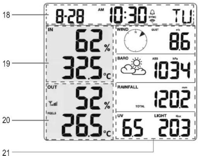
text_image
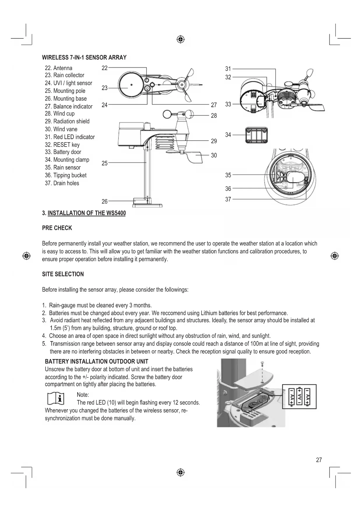
18 8-28 AM 10:30 TU IN 62% 325°C 19 OUT 52% FEELS 265°C 20 WIND GUST 8.6 BARO ABS NPa 1034 RAINFALL mm TOTAL 120.2 UV LIGHT Quc 65 20.3 21WIRELESS 7-IN-1 SENSOR ARRAY
- Antenna
- Rain collector
- UVI / light sensor
- Mounting pole
- Mounting base
- Balance indicator
- Wind cup
- Radiation shield
- Wind vane
- Red LED indicator
- RESET key
- Battery door
- Mounting clamp
- Rain sensor
- Tipping bucket
- Drain holes
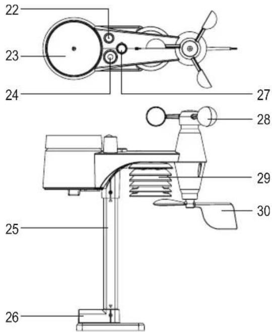
text_image
22 23 24 27 28 25 29 30 26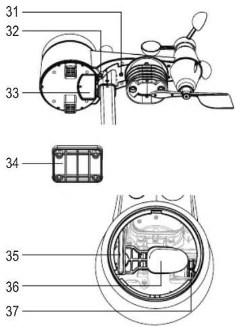
text_image
31 32 33 34 35 36 373. INSTALLATION OF THE WS5400
PRE CHECK
Before permanently install your weather station, we recommend the user to operate the weather station at a location which is easy to access to. This will allow you to get familiar with the weather station functions and calibration procedures, to ensure proper operation before installing it permanently.
SITE SELECTION
Before installing the sensor array, please consider the followings:
- Rain-gauge must be cleaned every 3 months.
- Batteries must be changed about every year. We recommend using Lithium batteries for best performance.
- Avoid radiant heat reflected from any adjacent buildings and structures. Ideally, the sensor array should be installed at 1.5m (5') from any building, structure, ground or roof top.
- Choose an area of open space in direct sunlight without any obstruction of rain, wind, and sunlight.
- Transmission range between sensor array and display console could reach a distance of 100m at line of sight, providing there are no interfering obstacles in between or nearby. Check the reception signal quality to ensure good reception.
BATTERY INSTALLATION OUTDOOR UNIT
Unscrew the battery door at bottom of unit and insert the batteries according to the +/- polarity indicated. Screw the battery door compartment on tightly after placing the batteries.

Note:
The red LED (10) will begin flashing every 12 seconds.
Whenever you changed the batteries of the wireless sensor, re-synchronization must be done manually.
text_image
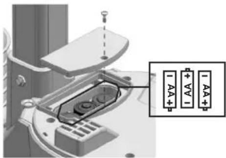
Technical diagram showing a mechanical component with labeled pins and a zoomed-in section view highlighting terminal labels AA, AA1, and A4A.INSTALLING THE MOUNTING POLE
- Insert the top side of the pole to the square hole of the weather sensor.

Ensure the pole and sensor's indicator align.
-
Place the nut in the hexagon hole on the sensor, then insert the screw in other side and tighten it by the screw driver.
-
Insert the other side of the pole to the square hole of the plastic stand.

Align the pole and stand marking.
- Place the nut in the hexagon hole on the sensor, then insert the screw in other side and tighten it by the screw driver.
natural_image
Technical line drawing of a mechanical component with an inset showing a close-up view of a dial indicator (no text or symbols present)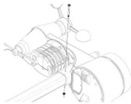
natural_image
Technical line drawing of a mechanical assembly with gears and shafts (no text or symbols)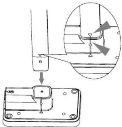
text_image
Technical diagram showing a mechanical assembly with an inset close-up of a component detail, labeled with Chinese character 'B' and arrow.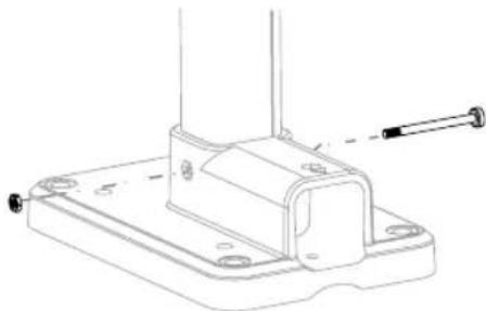
natural_image
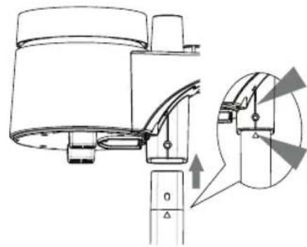
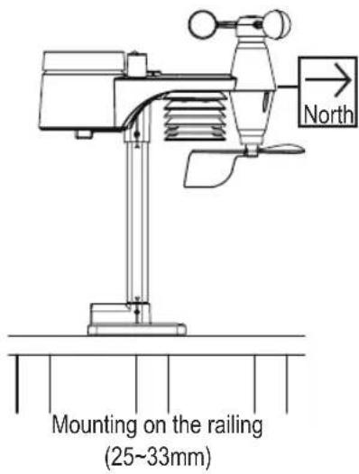
Technical line drawing of a mechanical bracket with mounting holes and a screw (no text or symbols)- Mount the wireless outdoor unit with the wind meter end pointing to the North to correctly orient direction of the wind vane.
text_image
Mounting on the railing (25~33mm) North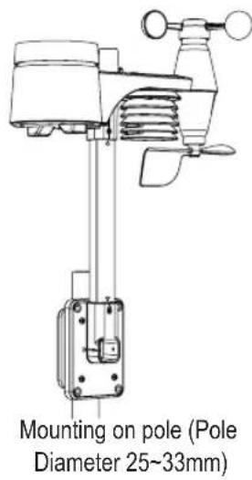
text_image
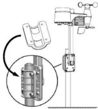
Mounting on pole (Pole Diameter 25~33mm)- When mounting on pole. Secure the vertically installed mounting stand and the included clamp to the post / pole using the included screws.
text_image
Technical diagram showing mechanical assembly with labeled components and a magnified inset view of a cylindrical component.Install the wireless WS5400 outdoor sensor at least 1.5m off the ground for better and more accurate wind measurements. Install the wireless WS5400 outdoor sensor as level as possible to achieve accurate rain and wind measurements. Install the wireless WS5400 outdoor sensor with the wind sensors pointing north. See point 5 of installing the mounting pole. Choose an open area within range of the display
BATTERY INSTALLATION INDOOR UNIT
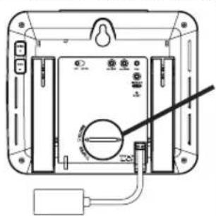
Backup battery provides power to the console to retain clock time and date, max/min records and calibration value.
natural_image
Diagram of a device rear panel with labeled ports and a cable, no readable text or symbols present| Step 1 Step 2 Step 3 | ||
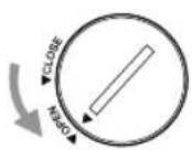 |  |  |
| Remove the console battery door with coin | Insert a new CR2032 button cell battery | Replace the battery door |
The backup battery can back up: Time & Date, Max/Min records and calibration value.
The built-in memory can back up: connection settings.
Please always remove the back-up battery if the device is not going to be used for a while. Please keep in mind that even when the device is not in use, certain settings, such as the clock, calibration and records in its memory, will still drain the back-up battery.
POWER UP THE DISPLAY
- Plug in the power adapter to power up the console.
- Once the console is power up, all the segments of the LCD will be shown.
- The console will automatically enter AP mode and sensor synchronization mode automatically.
MANUAL SYNCHRONISATION OF INDOOR AND OUTDOOR UNIT
Press the [Sensor / Wi-Fi] key once for the console to enter sensor Synchronization mode (channel number blinking), and the console will re-register all the sensors that have already been paired to it before.
Whenever you changed the batteries of the wireless sensor, re-synchronization must be done manually.
- Change all the batteries to new ones in the sensor.
- Press [Sensor / Wi-Fi] key on the console to enter sensor Synchronization mode.
- Console will re-register the sensor after its batteries are changed (about 1 minute).
REMOVE SENSOR CONNECTION
User may manually delete any sensor from the console.
- Press the [CH / SET] key until the console shows the display of the selected sensor.
- Press and hold [ REFRESH ] key for 10 seconds, until its readings are reset “ -- , -°C -- % “ is shown.
WIRELESS SENSOR SIGNAL STRENGTH
- The console display shows the signal strength of the wireless sensor(s), as per table below:
| Signal strength of outdoor 7-in-1 sensor | |||
| Signal strength of outdoor 7-in-1 sensor | |||
| No signal Weak signal Good signal | |||
- If the signal has discontinued and does not recover within 15 minutes, the signal icon will disappear. The temperature and humidity will display "Er" for the corresponding channel.
- If the signal does not recover within 48 hours, the "Er" display will become permanent. You need to replace the batteries and then press [Sensor / Wi-Fi] key to pair up the sensor again.
FACTORY HARD RESET
Indoor display unit
To reset the console and start again, press the [RESET] key once or remove the backup battery and then unplug the adapter. To resume factory settings and remove all data, press and hold the [RESET] key for 6 seconds.
Outdoor display unit
To reset the outdoor unit, press the [RESET] key once or remove the backup battery. To resume factory settings and remove all data, press and hold the [RESET] key for 6 seconds.
4. WORKING WITH THE SMARTLIFE APP
The console works with Smart Life APP for Android and iOS smart phone.
- Scan the QR code to go to the Smart Life download page
- Download Smart Life from Google Play or Apple APP store.
- Install the Smart Life APP.
- Follow the instruction to create your own account using phone number or email.
- Once the account registration is completed, the Home Screen will be shown.

Smart Life for Android / iPhone

There is no Registration code needed if email method is chosen.
The APP may be subject to change without notice.
You may be prompted to allow the APP to have access to your location. This will allow the APP to give you general weather information in your area. The APP will still work if you don't allow access to that.
CONNECT WEATHER STATION TO WI-FI NETWORK
- Press and hold the [SENSOR / Wi-Fi] key for 6 seconds to enter AP mode manually, indicated by blinking AP and When the console is power up for the first time, the console will automatically enter and stay at AP mode.
- Open Smart Life APP and follow the in-APP instructions to connect weather station to your Wi-Fi network.
- The console will automatically exit AP mode and return to normal operation once it's connected to Wi-Fi router.
Step 1:
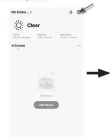
At the home screen, tap the on the top right corner to add your console.
text_image
My Home ... Clear 30°C 10.2 % 10/11 10:00 Air Devices ... No devices Add DeviceStep 2:
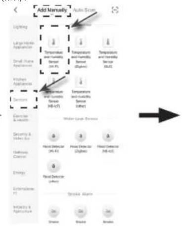
On "Add Manually" screen, choose "Sensors" in the left menu bar and then select "Temperature and Humidity Sensor (Wi-Fi)".
text_image
Add Manually Auto Scan Lighting Large Hydro Appliance Small Air Condition Kitchen Appliance Services Temperature and Humidity Sensor (100 Hz) Temperature and Humidity Sensor (200 Hz) Temperature and Humidity Sensor (300 Hz) Temperature and Humidity Sensor (400 Hz) Temperature and Humidity Sensor (500 Hz) Exercise & Measure Water Level Deviation Security & Measure Use Balance Control Energy Externalize Use Balance & Measure Water & Measure Heat Detector (90 Hz) Heat Detector (200 Hz) Heat Detector (300 Hz) Heat Detector (400 Hz) Stroke Alarm Stroke StrokeStep 3:
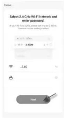
Make sure you select the 2.4G network and enter your Wi-Fi password then tap the "Next".
text_image
Cancel Select 2.4 GHz Wi-Fi Network and enter password. If you're Wi-Fi SGAHz, please add 3 to top 2.4GHz; Connect via the starting method x - 0.1 - 5GHz y - 0.1 - 3.4GHz - 2.4G HostStep 4:
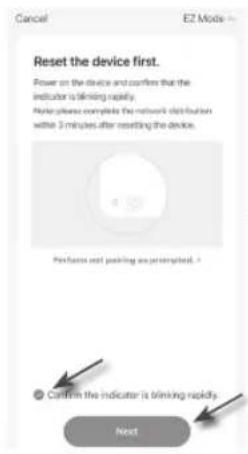
Confirm your device is in "AP mode" and tap "Next".
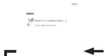
Step 6:
Once it success, the console icon will shown, and you can customize its information.
Step 5:
There will auto scan and register your device.
text_image
Added. Smart 7-in-1 weather station Device added successfully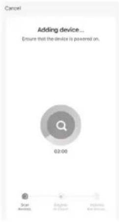
text_image
Cancel Adding device... Ensure that the device is powered on. 02:00 Scar Balance English in Excel Physical in Excel
text_image
Cancel E2 Mode Reset the device first. Power on the device and confirms that the indicator is blowing rapidly. Note please complete the network distribution within 3 minutes after resetting the device. Please wait or pickling as prompted. Confirm the indicator is blowing quickly. Next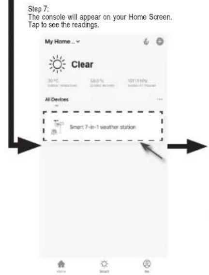
text_image
Step 7: The console will appear on your Home Screen. Tap to see the readings. My Home... Clear 30°C Clear (Temperature) 68.0% Improved airflow 120(114Kg) Sudden Air Flow All Devices Smart 7-in-1 weather station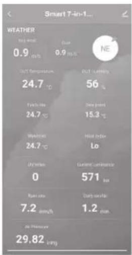
text_image
WEATHER 0.9 m/s Current 0.9 m/s NE CO2 Temperature 24.7 °C CO2 Leaching 56 °C Daily change 24.7 °C 15.3 °C Windbreak 24.7 °C Wind Index Lo Current Leaching 0 571 bar Daily change 7.2 mm/h 1.2 min. At Previous 29.82 long
Smart weather station can only connect to 2.4G Wi-Fi network

Enable the location information in your mobile when you add your console to APP.
SMARTLIFE WS5400 SCREEN OVERVIEW
The device home screen can show the IN, OUT and (CH) Channel's readings, also you can tap the top and bottom's icon to access other functions.
- Back icon for back to APP home page
- Device management icon for advance feature and firmware update
- OUTDOOR readings section
- INDOOR readings section
- CH1 \~ CH3 readings section (When multiple sensors are installed)
- MAX / MIN icon, tap to display the MAX / MIN page
- History graph icon
- Setting icon
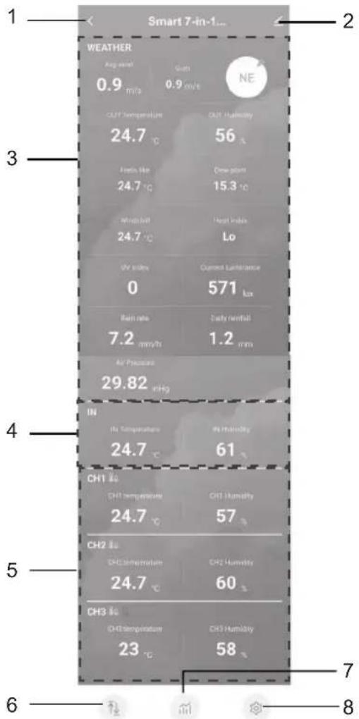
text_image
Smart 7-in-1... WEATHER Avg. mmol 0.9 m/s Sugm 0.9 m/s NE OUT Temperature 24.7 °C OUT Humidity 56 A Foats like 24.7 °C Cold storm 15.3 °C Wind off 24.7 °C Heat Index Lo UV stress Current Luminance 0 571 kx Rain rate 7.2 mm/ft Daily rainfall 1.2 mm Air Pressure 29.82 mHg IN Air Temperature 24.7 °C Air Humidity 61 CH1 30 CH1 temperature 24.7 °C CH1 Humidity 57 CH2 30 CH2 temperature 24.7 °C CH2 Humidity 60 CH3 30 CH3 temperature 23 °C CH3 Humidity 58 7 6 8Tap the MAX / MIN icon to enter the max / min records page.
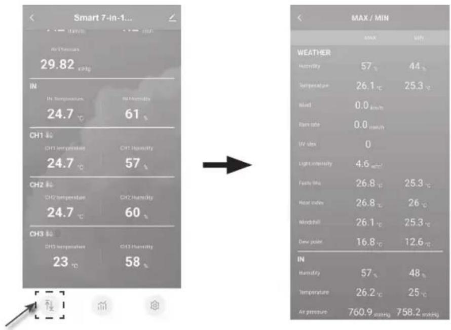
text_image
Smart 7-in-1... MAX / MIN 29.82 °C IN IN Temperature IN Humidity 24.7 °C 61 °C CH1 °C CH1 temperature CH2 Humidity 24.7 °C 57 °C CH2 °C CH2 temperature CH3 Humidity 24.7 °C 60 °C CH3 °C CH3 temperature CH3 Humidity 23 °C 58 °C WEATHER Humidity 57 °C 44 °C Temperature 26.1 °C 25.3 °C Wind 0.0 km/h Rain rate 0.0 mm/h UV max 0 Light intensity 4.6 mmHg Foels like 26.8 °C 25.3 °C Heat index 26.8 °C 26 °C Windball 26.1 °C 25.3 °C Dew point 16.8 °C 12.6 °C IN In humidity 57 °C 48 °C Temperature 26.2 °C 25 °C Air pressure 760.9 mmHg 758.2 mmHgTap the history graph icon to enter the history graph page.
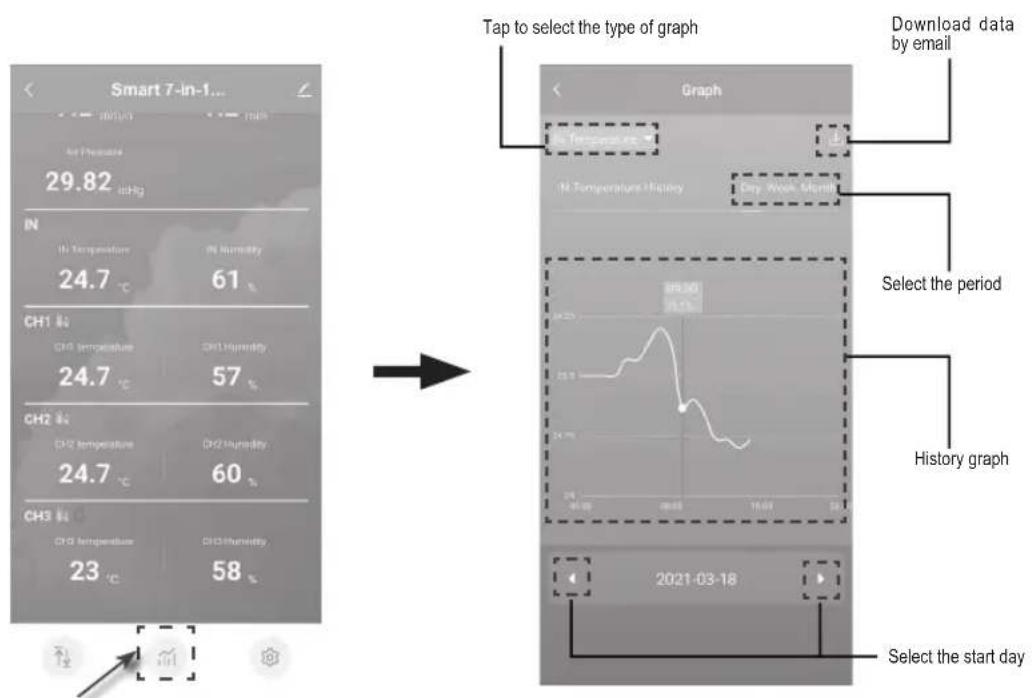
text_image
Smart 7-in-1... 29.82 in IN In Temperature 24.7 °C CH1 in CH2 in CH3 in CH2 in CH3 in 23 °C Tap to select the type of graph Download data by email In Temperature History Day Work Month Select the period History graph 2021-03-18 Select the start dayTap the Setting icon and then tap the unit row to set the display unit in this device pages of the APP
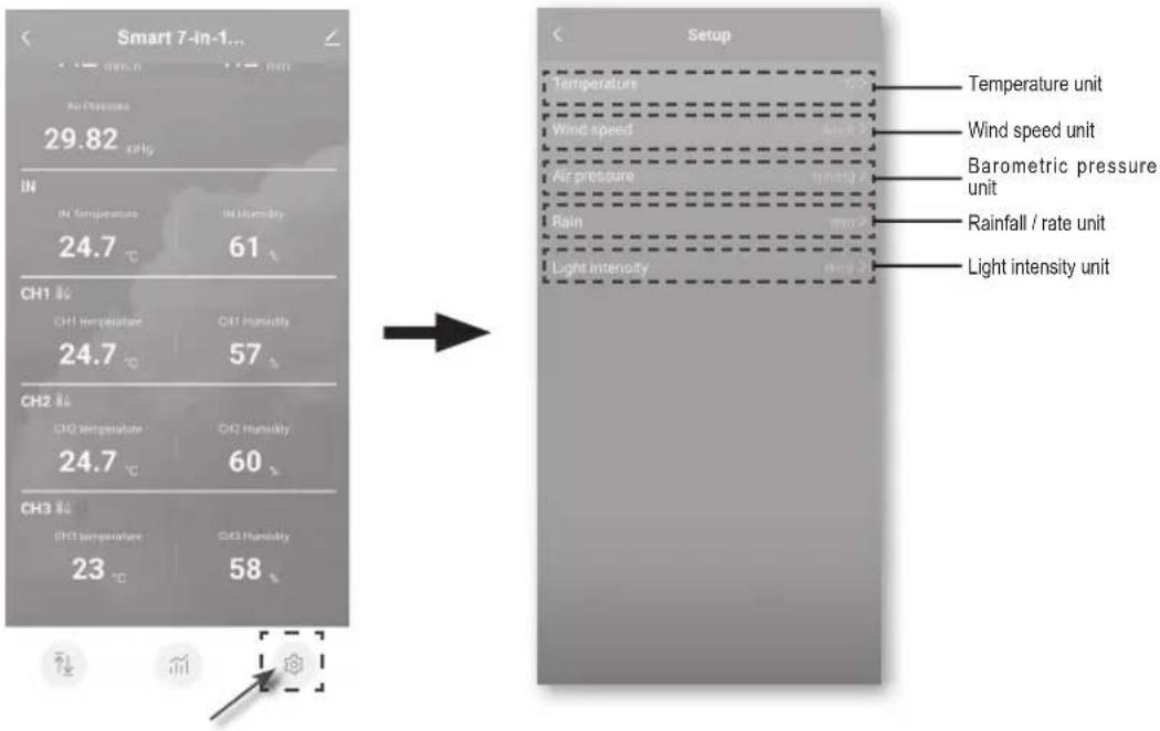
text_image
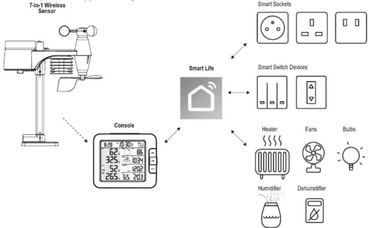
Smart 7-in-1... 29.82 °C Air Temperature IN IN Temperature IN Humidity 24.7 °C 61 CH1 %C CH1 Temperature CH1 Humidity 24.7 °C 57 CH2 %C CH2 temperature CH2 Humidity 24.7 °C 60 CH3 %C CH3 temperature CH3 Humidity 23 °C 58 Setup Temperature Wind speed Air pressure Rain Light intensity Temperature unit Wind speed unit Barometric pressure unit Rainfall / rate unit Light intensity unitAUTOMATION WITH OTHER DEVICES (IOT) USING SMART LIFE
Through the Smart life APP, you can the WS5400 data such as temperature and humidity as conditions to control other Smart Life compatible device(s) automatically.
flowchart
graph TD
    A["7-in-1 Wireless Sensor"] --> B["Console"]
    B --> C["Smart Life"]
    C --> D["Smart Switch Devices"]
    D --> E["Heater"]
    D --> F["Fans"]
    D --> G["Bulbs"]
    B --> H["7-in-1 Wireless Sensor"]
    C --> I["Smart Sockets"]
    C --> J["Smart Switch Devices"]
    C --> K["Heater"]
    C --> L["Fans"]
    C --> M["Bulbs"]
This can be set up by creating smart scenario's in the Smart life app. When a certain condition is met it triggers actions in other smart products working with Smart life.
flowchart
graph LR
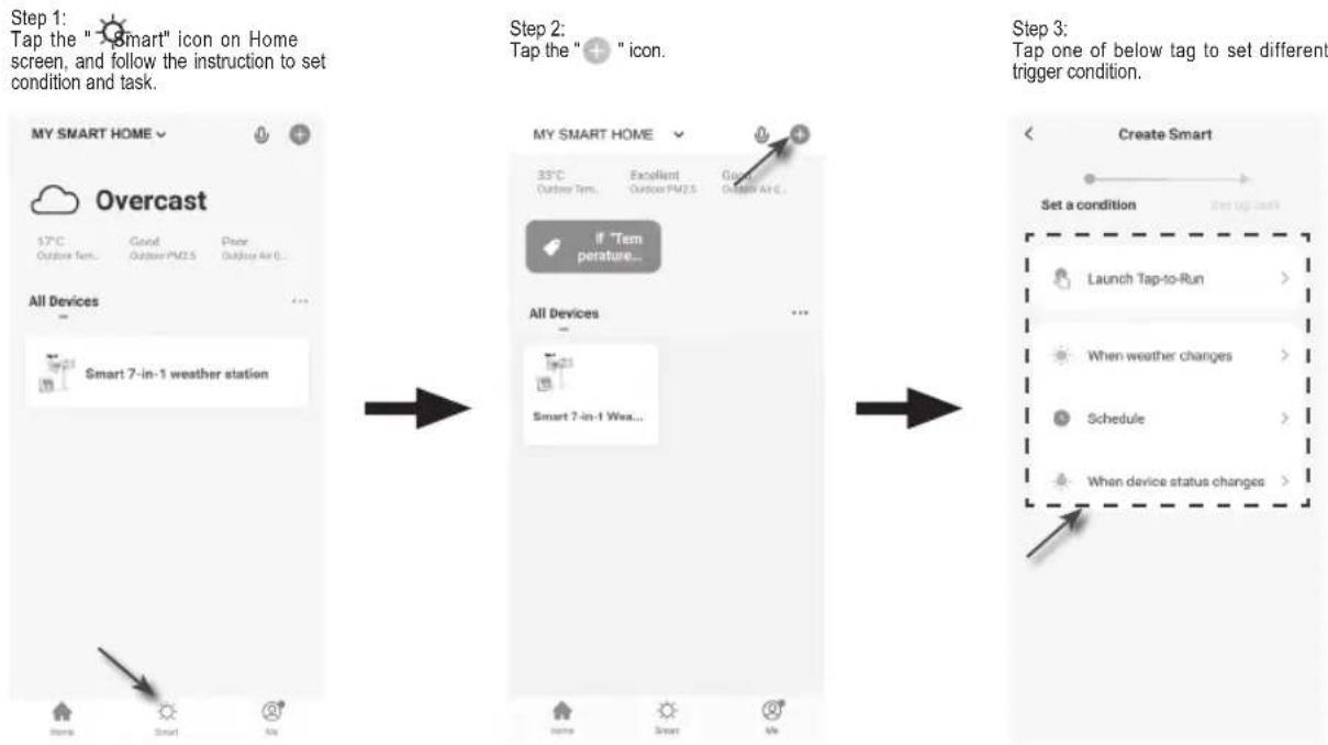
A["Step 1: Tap the "Smart" icon on Home screen, and follow the instruction to set condition and task."] --> B["Step 2: Tap the "Icon""]
B --> C["Step 3: Tap one of below tag to set different trigger condition."]

Any tasks required or performed by third party devices are at user's own choice and risk.
5. UPDATING THE WS5400 (FIRMWARE)
The console can be updated through your Wi-Fi network. If new firmware is available, a notification or pop up message will be shown on your mobile when you open the APP. Follow the instruction in the APP to do the update.

- During the update process, the console will show the progress status percentage at the middle of the screen. Once the update complete, the console screen will reset and back to normal mode.
- Please keep the power connection during the firmware update process.
- Please make sure your console Wi-Fi connection is stable.
- When the update process start, do not operate the console until the update is finished.
- Settings and data maybe lost during update.
- During firmware update the console will stop to upload data to the cloud server. It will reconnect to your Wi-Fi router and upload the data again once the firmware update succeed. If the console cannot connect to your router, please enter the SETUP page to setup again.
- If firmware update fail, press and hold the [ALARM] and [CAL] key at the same time with 10 seconds to go back to the original version, then redo the update procedure again.
6. SETTINGS & FUNCTIONS OF THE CONSOLE
The setting mode can set the time, date, unit of measure and other functions.
Use the below keys to scroll through the setup menu, change values and confirm changes.
Press and hold [CH / SET] key for 2 seconds to enter the setting Mode.
Short press [CH / SET] key to proceed to the next setting step.
Press [WIND / + ] or [NDX / - ] key to change the value. Press and hold the key for quick-adjust.
Press and hold [CH / SET] key for 2 seconds to exit the SET mode at any time.


This console is designed to automatically obtain the local time by synchronizing with your local time. If you want to use it off line, you can set the time and date manually.
Setting items table
| Step Mode Setting procedure | |
| 1 12/24 hour format Press [ WIND / + ] or [ NDX / - ] key to select 12 or 24 hour format | |
| 2 Hour Press [ WIND / + ] or [ NDX / - ] key to adjust the hour | |
| 3 Minute Press [ WIND / + ] or [ NDX / - ] key to adjust the minute | |
| 4 Year Press [ WIND / + ] or [ NDX / - ] key to adjust the year | |
| 5 M-D/D-M format Press [ WIND / + ] or [ NDX / - ] key to select "Month / Day" or "Day / Month" display format | |
| 6 Month Press [ WIND / + ] or [ NDX / - ] key to adjust the month | |
| 7 Day Press [ WIND / + ] or [ NDX / - ] key to adjust the day | |
| 8 Time sync ON/OFF Press [ WIN D / + ] or [ NDX / - ] key to enable or disable time sync functionIf you want to set the time manually, you should set time sync OFF | |
| 9 Weekday Language Press [ WIND / + ] or [ NDX / - ] key to select weekday display language |
| Step Mode Setting procedure | ||
| 10 Temperature unit Press [ WIND | / + ] or [ NDX / - ] key to change the rain display unit between °C or °F | |
| 11 | Wind speed unit | Press [ WIND / + ] or [ NDX / - ] key to change the unit in sequence: m/s → km/h → knots -mph |
| 12 Baro unit Press [ WIND / + ] or | [ NDX / - ] key to change the unit in sequence: hPa inHg → mmHg | |
| 13 Rain unit Press [ WIND / + ] or | [ NDX / - ] key to change the rain display unit between mm or in | |
| 14 Light intensity unit Press [ WIND | / + ] or [ NDX / - ] key to change the Light intensity unit in sequence: Klux → Kfc W/m2. | |
| 15 Channel auto loop Press [ WIND | / + ] or [ NDX / - ] key to enable or disable channel auto loop function | |
| 16 7-in-1 sensor point to Press [ W | IND / + ] or [ NDX / - ] key to select the sensor located hemisphere (e.g. US and EU countries are also "N", Australia is "S") | |

Console will exit setting mode automatically, if no operation after 60 seconds.
SETTING ALARM TIME
- In normal time mode, press and hold [ALARM] key for 2 seconds until the alarm hour digit flashes to enter alarm time setting mode.
- Press [WIND / + ] or [NDX / - ] key to change the value. Press and hold the key for quick-adjust.
- Press [ ALARM ] key again to step the setting value to Minute with the Minute digit flashing.
- Press [WIND / + ] or [NDX / - ] key to adjust the value of the flashing digit.
- Press [ ALARM ] key to save and exit the setting.
- When enabled the 🔔 icon will be visible on the LCD.
ACTIVATING THE ALARM FUNCTION
- In normal mode, press [ ALARM ] key to show the alarm time for 5 seconds.
- When the alarm time displays, press [ ALARM ] key again to activate the alarm function.
| Alarm off | Alarm on |
When clock reaches the alarm time, the alarm function will be triggered. The alarm can be stopped by either of the following 4 operations
- After 2 minutes of alarm the alarm will stop automatically while staying activated for the next day.
- By pressing [SNOOZE / CONTRAST] key to enter snooze mode that will postpone the alarm by 5 minutes.
- By holding [SNOOZE / CONTRAST] key for 2 seconds to stop the alarm and will activate again in the next day
- By pressing [ ALARM ] key to stop the alarm and the alarm will activate again in the next day.
The temperature and humidity reading are displayed on the outdoor and indoor / CH section.
If the reading is below the measurement range, it will show "LO". If reading is above the measurement range, it will show "HI".
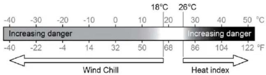
FEELS LIKE, HEAT INDEX, WIND CHILL & DEW POINT

Feels like, Heat index, Wind chill & Dew point can be viewed in the OUT temperature section. During normal operation, press [NDX / - ] key to switch the OUT temperature as below sequence:
OUT temperature → Feels like → Heat index Wind chill Dew point
FEELS LIKE
Feels Like Temperature shows what the outdoor temperature will feel like. It's a collective mixture of Wind Chill factor and the Heat Index. For temperatures in the region between 18.1°C to 25.9°C where both wind and humidity are less significant in affecting the temperature, the device will show the actual outdoor measured temperature as Feels Like Temperature.
text_image
-40 -30 -20 -10 0 10 20 30 40 50 °C Increasing danger Increasing danger -40 -22 -4 14 32 50 68 86 104 122 °F Wind Chill Heat indexDEW POINT
The dew point is the temperature below which the water vapor in air at constant barometric pressure condenses into liquid water at the same rate at which it evaporates. The condensed water is called dew when it forms on a solid surface.
The dew point temperature is determined by the temperature & humidity data from wireless 7-IN-1 sensor.
HEAT INDEX
The heat index which is determined by the wireless 7-IN-1 sensor's temperature & humidity data when the temperature is between 26^ (79°F) and 50^ (120°F).
| HEAT INDEX RANGE WARNING EXPLANATION | ||
| 27°C to 32°C (80°F to 90°F) Caution Possibility of heat exhaustion | ||
| 33°C to 40°C (91°F to 105°F) Extreme caution Possibility of heat dehydration | ||
| 41°C to 54°C (106°F to 129°F) Danger Heat exhaustion likely | ||
| ≥55°C (≥130°F) Extreme danger Strong risk of dehydration / sun stroke | ||
WIND CHILL
A combination of the wireless 7-IN-1 sensor's temperature and wind speed data determines the current wind chill factor.
WIND
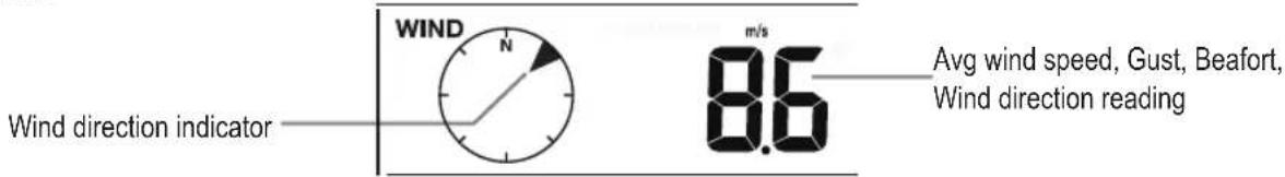
text_image
Wind direction indicator WIND N m/s 8.6 Avg wind speed, Gust, Beafort, Wind direction readingTO SELECT THE WIND DISPLAY MODE
In normal mode, press [WIND / + ] key to switch between AVERAGE wind speed, GUST, wind direction and BEAUFORT scale (BFT).
The Beaufort scale is an international scale of wind velocities ranging from 0 (calm) to 12 (Hurricane force).
| Beaufort Scale Description Wind | Speed Land Condition | ||
| 0 Calm | < 1 km/h | Calm. Smoke rises vertically. | |
| < 1 mph | |||
| < 1 knots | |||
| < 0.3 m/s | |||
| 1 Light air | 1.1 ~ 5km/h | Smoke drift indicates wind direction.Leaves and wind vanes are stationary. | |
| 1 ~ 3 mph | |||
| 1 ~ 3 knots | |||
| 0.3 ~ 1.5 m/s | |||
| 2 Light breeze | 6 ~ 11 km/h | Wind felt on exposed skin. Leaves rustle.Wind vanes begin to move. | |
| 4 ~ 7 mph | |||
| 4 ~ 6 knots | |||
| 1.6 ~ 3.3 m/s | |||
| 3 Gentle breeze | 12 ~ 19 km/h | Leaves and small twigs constantly moving, light flags extended. | |
| 8 ~ 12 mph | |||
| 7 ~ 10 knots | |||
| 3.4 ~ 5.4 m/s | |||
| 4 | Moderate breeze | 20 ~ 28 km/h | Dust and loose paper raised. Small branches begin to move. |
| 13 ~ 17 mph | |||
| 11 ~ 16 knots | |||
| 5.5 ~ 7.9 m/s | |||
| 5 Fresh breeze | 29 ~ 38 km/h | Branches of a moderate size move.Small trees in leaf begin to sway. | |
| 18 ~ 24 mph | |||
| 17 ~ 21 knots | |||
| 8.0 ~ 10.7 m/s | |||
| 6 Strong breeze | 39 ~ 49 km/h | Large branches in motion. Whistling heard in overhead wires. Umbrella use becomes difficult. Empty plastic bins tip over. | |
| 25 ~ 30 mph | |||
| 22 ~ 27 knots | |||
| 10.8 ~ 13.8 m/s | |||
| 7 High wind | 50 ~ 61 km/h | Whole trees in motion. Effort needed to walk against the wind. | |
| 31 ~ 38 mph | |||
| 28 ~ 33 knots | |||
| 13.9 ~ 17.1 m/s | |||
| 8 Gale | 62 ~ 74 km/h | Some twigs broken from trees.Cars veer on road. Progress on foot is seriously impeded | |
| 39 ~ 46 mph | |||
| 34 ~ 40 knots | |||
| 17.2 ~ 20.7 m/s | |||
| 9 Strong gale | 75 ~ 88 km/h | Some branches break off trees, and some small trees blow over. Construction / temporary signs and barricades blow over. | |
| 47 ~ 54 mph | |||
| 41 ~ 47 knots | |||
| 20.8 ~ 24.4 m/s | |||
| 10 Storm | 89 ~ 102 km/h | Trees are broken off or uprooted, structural damage likely. | |
| 55 ~ 63 mph | |||
| 48 ~ 55 knots | |||
| 24.5 ~ 28.4 m/s | |||
| 11 Violent storm | 103 ~ 117 km/h | Widespread vegetation and structural damage likely. | |
| 64 ~ 73 mph | |||
| 56 ~ 63 knots | |||
| 28.5 ~ 32.6 m/s | |||
| 12 Hurricane force | ≥ 118 km/h | Severe widespread damage to vegetation and structures. Debris and unsecured objects are hurled about. | |
| ≥ 74 mph | |||
| ≥ 64 knots | |||
| ≥ 32.7m/s | |||
WEATHER FORECAST
The built-in barometer continually monitors atmospheric pressure. Based on the data collected, it can predict the weather conditions in the forthcoming 12\~24 hours within a 30\~50km (19\~31 miles) radius.
The accuracy of a general pressure-based weather forecast is about 70% to 75%.
The weather forecast is reflecting the weather situation for next 12\~24 hours, it may not necessarily reflect the current situation.
The SNOWY weather forecast is not based on the atmospheric pressure, but based on the temperature of outdoor. When the temperature is below -3^ (26°F), the SNOWY weather icon will be displayed on the LCD.
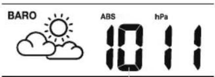
BAROMETRIC PRESSURE
The atmospheric pressure is the pressure at any location of the earth caused by the weight of the column of air above it. One atmospheric pressure refers to the average pressure and gradually decreases as altitude increases. Meteorologists use barometers to measure atmospheric pressure. Since variation in atmospheric pressure greatly affected by weather, it is possible to forecast the weather by measuring the changes in pressure.
text_image
BARO ABS hPa 10 11Baro pressure reading
In normal mode, press [ BARO ] key to switch between ABSOLUTE / RELATIVE barometric pressure.
To set up the relative pressure:
- Press and hold [ BARO ] key for 2 seconds to enter relative pressure setting mode.
- Press [WIND / + ] or [NDX / - ] key to set the value
- Press [ BARO ] key to exit the setting.
RAIN
To select the rainfall display mode Press [RAIN] key to toggle between:
- DAILY - the total rainfall from midnight (default)
- WEEKLY - the total rainfall of the current week
- MONTHLY- the total rainfall of the current calendar month
- TOTAL - the total rainfall since the last reset
- RATE - Current rainfall rate (base on 10 min rain data)
Period of rainfall and rain rate
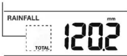
text_image
RAINFALL TOTAL mm 120.2
In normal mode, press and hold [Rain] key for 6 seconds to reset all the rainfall records.
To ensure to have correct data, please reset all the rainfall record when you re-install your wireless 7-IN-1 sensor to other location.
LIGHT INTENSITY & UV INDEX
The UV index and light intensity reading show on the bottom right side of the display.
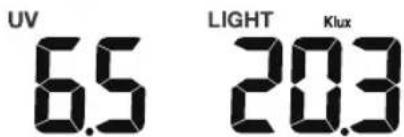
text_image
UV 6.5 LIGHT 20.3 KluxThe console can show the different reading's daily MAX / MIN records in memory mode. To view MAX / MIN records

In normal mode, press [MEM] key on the front side, to check records in below sequence: Indoor or current CH MAX temperature – indoor or current CH MIN temperature Indoor or current CH MAX humidity → Indoor or current CH MIN humidity – outdoor MAX temperature outdoor MIN temperature outdoor MAX humidity – outdoor MIN humidity MAX Feels like temperature MIN-Feels like temperature MAX heat index temperature – MIN wind chill temperature MAX dew point temperature MIN dew point temperature MAX → average wind speed – MAX gust wind MAX Beaufort MAX relative baro pressure MIN relative baro pressure → MAX absolute baro pressure – MIN absolute baro pressure MAX rain rate MAX UV index, MAX light intensity. Then press [MEM] key for back to normal mode. You can also, press another key to exit memory mode.

Press and hold [MEM] key for 2 seconds to reset the current displayed record.
CALIBRATION
The console is able to calibrate the weather readings:
- In normal mode, press and hold [CAL] key for 2 seconds to enter the calibration mode as shown on the right.
- Press [CH / SET] key to select different parameter as sequence: Indoor temperature → Indoor humidity -CH temperature CH humidity → outdoor temperature -outdoor humidity wind speed wind direction → absolute baro pressure rain gain UV gain light intensity gain.
- While the reading is blinking, press [WIND / +] or [-] key to adjust the offset value.
- When finished, press [CH/SET] to proceed with next calibration by repeating process 2 - 3 above.
- To return normal mode, press [CAL] key once.
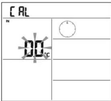
text_image
CAL IN 00°CBACK LIGHT
The main unit back light can be adjusted, using the [ON/AUTO] sliding switch to select the Appropriate brightness:
Slide to the [ON] position to set the back light to normal brightness.
Slide to the [AUTO] position to set the back light brightness that according to ambient light level.
SET LCD DISPLAY CONTRAST
In normal mode, press [ SNOOZE / CONTRAST ] key to adjust LCD contrast for best viewing on table stand or wall mounted.
7. MAINTENANCE
BATTERY REPLACEMENT
When low battery indicator "☐" is displayed in Out or CH section of the LCD display, it indicates that the wireless 7-in-1 or current channel sensor battery power give wireless sensor shown is low respectively. Please replace with new batteries.
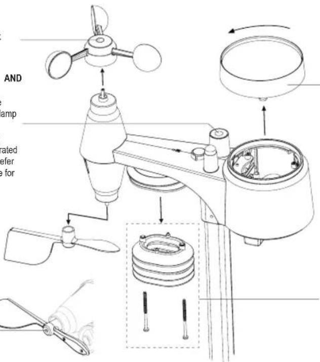
WIRELESS 7-IN-1 SENSOR MAINTENANCE
REPLACE THE WIND CUP
- Remove rubber cap and Unscrew
- Remove the wind cup for replacement
CLEANING THE UV SENSOR AND CALIBRATION
- For precision UV measurement, gentle clean the UV sensor cover lens with damp micro-fiber cloth.
• Over time, the UV sensor will naturally degrade. The UV sensor can be calibrated with a utility grade UV meter, please refer to Calibration section in previous page for about the UV sensor calibration.
REPLACE THE WIND VANE
Unscrew and remove the wind vane for replacement
text_image
AND amp rated refer e forCLEANING THE RAIN COLLECTOR
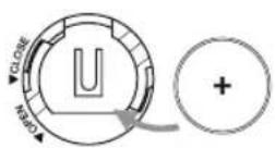
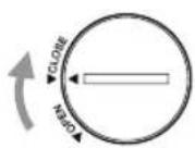
- Rotate the rain collector by turning it 30°anti-clockwise.
- Gently remove the rain collector.
- Clean and remove any debris or insects.
- Install the collector when it is clean and fully dried.
CLEANING HYGRO-THERMO SENSOR
- Remove the 2 screws at the bottom of the radiation shield.
- Gently pull out the bottom 4 shields.
- Carefully remove any dirt or insects on the sensor and ventilation fan (do not let the sensors inside get wet).
- Clean the shield with water to remove any dirt or insects.
- Install all the parts back when they are clean and fully dried.
9 TROUBLESHOOTING
| Problems Solution | |
| Strange or no measurement of Rain Sensor | 1. Check the drain hole in the rain collector.2. Check the balance indicator. |
| Strange or no measurement of Thermo / Hygro Sensor | 1. Check the radiation shield.2. Check the sensor casing. |
| Strange or no measurement of Wind Speed and Direction | 1. Check wind cups (Anemometer).2. Check the wind vane. |
| Y and ---(Signal lost for 15 minutes)Y and (Signal lost for 1 hour) | 1. Relocate the console and 7-IN-1 sensor closer to each other.2. Make sure the console is placed away from other electronic Appliances that may interfere with the wireless communication (TVs, computers, microwaves).3. If problem continues, reset both console and 7-IN-1 sensor. |
| Out temperature reading too high in the day time | Make certain that the sensor array is not too close to heat generating sources or structures, such as buildings, pavement, walls or air conditioning units. |
| Some condensation beneath the UV sensor may occur overnight | This will disappear when temperature rises up under the sun and will not affect the performance of the unit. |
| No Wi-Fi connection 1. Check for Wi-Fi symbol on the display, it should be always on.2. Make sure you connect to 2.4G band but not 5G band of your Wi-Fi router. | |
| Temperature or humidity not accurate | 1. Do not place your console or sensor close to the heat source2. If the sensor still not accurate adjust the value in calibration mode. |
8. SPECIFICATIONS
Indoor console unit
| General Specification | |
| Dimensions (W x H x D) 130 x 112 x 27.5mm (5.1 x 4.4 x 1.1 in) | |
| Weight 220g (with batteries) | |
| Main power DC 5V, 1A adaptor | |
| Backup battery CR2032 (excluded) | |
| Operating temperature range -5°C ~ 50°C | |
| Operating Humidity range 10~90% RH | |
| Support sensors | - 1 Wireless 7-in-1 sensor (included) |
| RF frequency(Depend on country version) | 868Mhz (EU or UK version) / |
| Time Related Function Specification | |
| Time display | HH: MM |
| Hour format | 12hr AM / PM or 24 hr |
| Date display | DD / MM or MM / DD |
| Time synchronize method | Through the server to get the local time of the console location |
| Weekday languages | EN / DE / FR / ES / IT / NL / RU |
| BAROMETER | |
| Barometer unit | hPa, inHg and mmHg |
| Accuracy | (700 ~ 1100hPa ± 5hPa) / (540 ~ 696hPa ± 8hPa) (20.67 ~ 32.48inHg ± 0.15inHg) / (15.95 ~ 20.55inHg ± 0.24inHg) (525 ~ 825mmHg ± 3.8mmHg) / (405 ~ 522mmHg ± 6mmHg) Typical at 25°C (77°F) |
| Resolution 1 hPa / inHg is 2 decimal | place / mmHg is 1 decimal place |
| In Temperature | |
| Temperature unit °C and °F | |
| Accuracy | <0°C or >40°C ± 2°C (<32°F or >104°F ± 3.6°F)0~40°C ±1°C (32~104°F ± 1.8°F) |
| Resolution °C / °F (1 decimal place) | |
| In Humidity | |
| Humidity unit % | |
| Accuracy | 1 ~ 20% RH ± 6.5% RH @ 25°C (77°F)21 ~ 80% RH ± 3.5% RH @ 25°C (77°F)81 ~ 99% RH ± 6.5% RH @ 25°C (77°F) |
| Resolution 1% | |
| Out Temperature | |
| Temperature unit °C and °F | |
| Accuracy | 5.1 ~ 60°C ± 0.4°C (41.2 ~ 140°F ± 0.7°F)-19.9 ~ 5°C ± 1°C (-3.8 ~ 41°F ± 1.8°F)-40 ~ -20°C ± 1.5°C (-40 ~ -4°F ± 2.7°F) |
| Resolution °C / °F (1 decimal place) | |
| Out Humidity | |
| Humidity unit % | |
| Accuracy | 1 ~ 20% RH ± 6.5% RH @ 25°C (77°F)21 ~ 80% RH ± 3.5% RH @ 25°C (77°F)81 ~ 99% RH ± 6.5% RH @ 25°C (77°F) |
| Resolution 1% | |
| Operating frequency : 2.4GHz | |
| APP Specification | |
| Support APP | - Tuya smart- Smart Life |
| Supported platform of APP | Android smart phoneiPhone |
Wireless 7-in-1 outdoor station
| Dimensions (W x H x D) 343.5 x 393 | .5 x 136mm (13.5 x 15.5 x 5.35in) installed mounting |
| Weight 757g (with batteries) | |
| Main power | 3 x AA size 1.5V batteries (Excluded)( Lithium batteries recommended) |
| Weather data | Temperature, Humidity, Wind speed, Wind direction, Rainfall, UV and light intensity |
| RF transmission range 150m | |
| RF frequency (depend on country version) | 868Mhz (EU, UK) |
| Transmission interval | 60 seconds for temperature and humidity12 seconds for Wind, rain, UV and light intensity |
| Operating range -40 ~ 60°C (-40 ~ 140°F) Lithium batteries required | |
| Operating humidity range 1 ~ 99% RH | |
TABLE DES LANGUES
- FRANÇAIS
46
FRANÇAIS
TABLE DES MATIÈRES
- INTRODUCTION......47
- APERÇU DU PRODUIT....48
- INSTALLATION DU WS5400 49
- UTILISATION DE L'APPLICATION SMARTLIFE 53
- MISE À JOUR DU WS5400 (MICROLOGICIEL)....58
- RÉGLAGES ET FONCTIONS DE LA CONSOLE....58
- MAINTENANCE....64
- CARACTÉRISTIQUES TECHNIQUES ......66
À PROPOS DU MANUEL UTILISATEUR

2. APERÇU DU PRODUIT
AFFICHAGE

text_image
EMSOX/CONTRAST 1
text_image
8:28 °C 10:30 °C TU 62% 325°C OUT 52% 265°C WIND 86 RADD 1011 RAINFALL 1202 UN 65 203 NEJM RAM SARO 2 3 4 5

text_image
Labeled diagram of a device rear panel with numbered components and portstext_image
Diagram showing battery terminal connections with labeled positive and negative charge carriers (AA+) and AY1, AY2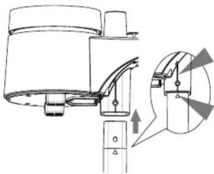
natural_image
Technical diagram of a mechanical device with an inset close-up showing internal components (no text or symbols)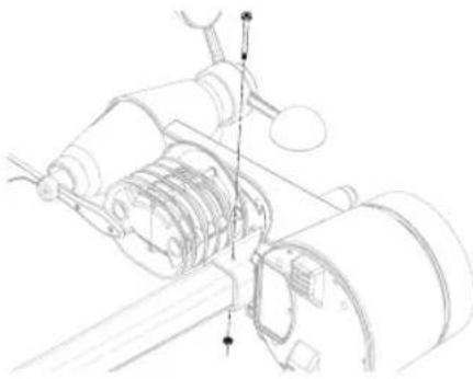
natural_image
Technical line drawing of a mechanical assembly with gears and shafts (no text or symbols)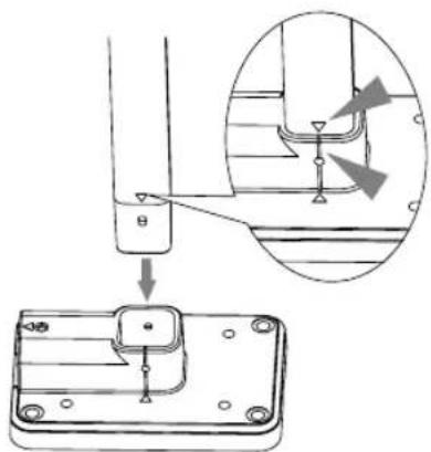
text_image
Technical diagram showing a mechanical assembly with an inset close-up of a component detail, likely illustrating a step-by-step assembly or installation.natural_image
Technical line drawing of a mechanical bracket with mounting holes and a screw (no text or symbols)text_image
Technical diagram showing a weather monitoring device with a rotating arm and a close-up of its internal structure.natural_image
Diagram of a device rear panel with a cable inserted, showing ports and wiring (no text or labels)natural_image
Line drawing of a hand holding a flat blade, with no text or symbols present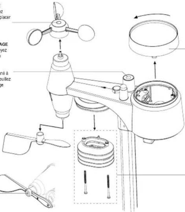
text_image
Technical diagram of a mechanical device with labeled parts and exploded view, including fan, propeller, and housing components.NETTOYAGE DU COLLECTEUR DE PLUIE
text_image
ENSOX/CONTRACT 1
text_image
8:28 °C 10:30 °C TU 62% 325°C OUT 52% 265°C WIND 86 RADD 1011 RUN /\ALL 1202 UN 65 203 2 3 4 5 BAND

text_image
Labeled diagram of a device rear panel with numbered components and portstext_image
Technical diagram of a mechanical device with numbered parts for identification3. MONTAGE DER WS5400
VORPRÜFUNG
text_image
Diagram showing battery terminal connections with labeled positive and negative charge carriers (AA+) and AY1, AY2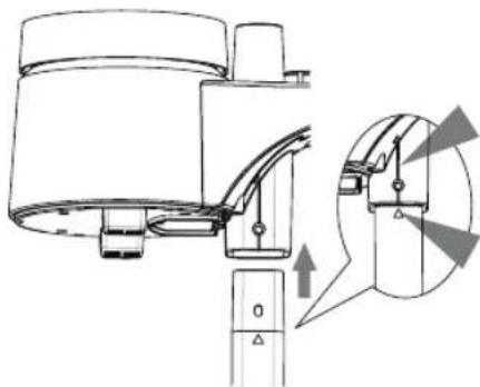
natural_image
Technical line drawing of a mechanical device with an inset showing a close-up of a component (no text or symbols present)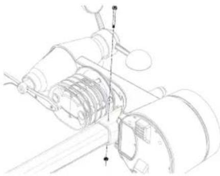
natural_image
Technical line drawing of a mechanical assembly with gears and shafts (no text or symbols)
text_image
Technical diagram showing a mechanical assembly with an inset close-up of a component detail, labeled with Chinese character 'B' and arrow.natural_image
Technical line drawing of a mechanical bracket with mounting holes and a screw (no text or symbols)natural_image
Technical line drawing of a mechanical device with no visible text or symbolstext_image
Technical diagram showing mechanical assembly with labeled components and a magnified inset view of a cylindrical component.natural_image
Diagram of a device rear panel with a cable inserted, showing ports and wiring (no text or labels)DEW POINT (TAUPUNKT)
natural_image
Line drawing of a spatula with a handle, no text or symbols present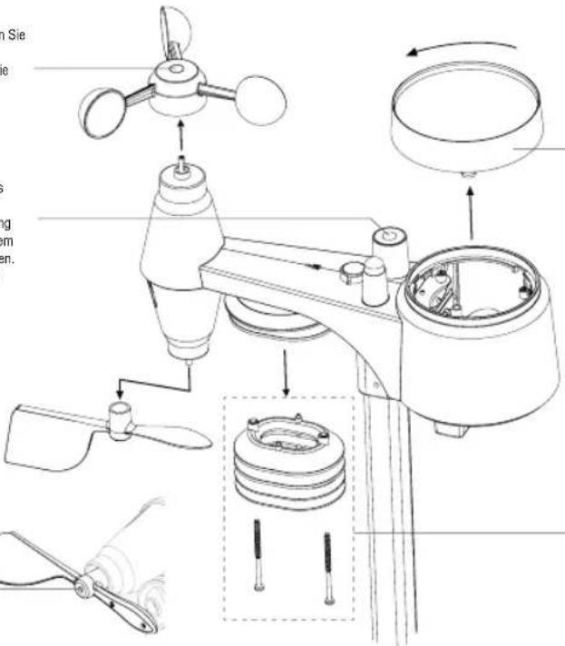
Manufacturers name and address : Dongguan Shijie Hua Xu Electronics Factory, No. 200, Technology East Road, Shijie Town, Dongguan City, Guangdong, P.R. China.
Model Identifier : HX075-0501000-AG-001
Average active efficiency : 76.81 %
Efficiency at low 10% load : -
No load Power consumption : 0.087 W
DECLARATION OF CONFORMITY
Hereby, Hesdo declares that the radio equipment type Alecto WS5400 is in compliance with directive 2014/53/EU. The full text of the EU declaration of conformity is available at the following internet address: http://DOC.hesdo.com/WS5400_DOC.pdf