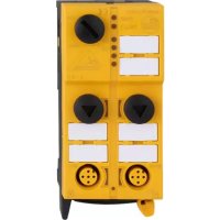
AC505S - Sensor IFM - Free user manual and instructions
Find the device manual for free AC505S IFM in PDF.


User questions about AC505S IFM
0 question about this device. Answer the ones you know or ask your own.
Ask a new question about this device
Download the instructions for your Sensor in PDF format for free! Find your manual AC505S - IFM and take your electronic device back in hand. On this page are published all the documents necessary for the use of your device. AC505S by IFM.
USER MANUAL AC505S IFM
Original operating instructions
Safe AS-Interface module Classic
Line
AC507S
Contents
1 Preliminary note 3
1.1 Symbols used 3
1.1.1 Safety symbol on the device 3
1.2 Warnings.... 3
2 Safety instructions.... 4
2.1 Safety-related requirements regarding the application 4
3 Transport, handling and storage 5
4 Items supplied.... 6
5 Intended use.... 7
6 Function description 8
7 Installation.... 9
7.1 General notes on wiring 14
7.2 Removing the connector with vibration protection 15
8 Electrical connection.... 16
8.1 Pin assignment 16
8.2 Functional earth 17
8.3 Wiring examples 17
8.4 Electronic contacts 18
9 Operating and display elements 20
9.1 Troubleshooting 20
10 Parameter setting 21
10.1 Addressing 21
11 Operation 22
11.1 Data bits 22
11.2 Parameters 23
11.3 Response times 24
12 Technical data.... 25
13 Approvals / certificates 29
14 Maintenance, repair and disposal 30
1 Preliminary note
You will find instructions, technical data, approvals, accessories and further information using the QR code on the device / packaging or at documentation.ifm.com.
1.1 Symbols used
√ Requirement
Instructions
Reaction, result
[...] Designation of keys, buttons or indications
→ Cross-reference

Important note
Non-compliance may result in malfunction or interference.

Information
Supplementary note
1.1.1 Safety symbol on the device

Safety symbol on the device:
▶ Adhere to the operating instructions for the safe operation of the unit.
1.2 Warnings
Warnings indicate the possibility of personal injury and damage to property. This enables safe product handling. Warnings are graded as follows:

WARNING
Warning of serious personal injury
▷ If the warning is not observed, fatal and serious injuries are possible.

CAUTION
Warning of minor to moderate personal injury
▷ If the warning is not observed, minor to moderate injuries are possible.
ATTENTION
Warning of damage to property
▷ If the warning is not observed, damage to property is possible.
2 Safety instructions
- The unit described is a subcomponent for integration into a system.
- The system architect is responsible for the safety of the system.
-
The system architect undertakes to perform a risk assessment and to create documentation in accordance with legal and normative requirements to be provided to the operator and user of the system. This documentation must contain all necessary information and safety instructions for the operator, the user and, if applicable, for any service personnel authorised by the architect of the system.
-
Read this document before setting up the product and keep it during the entire service life.
- The product must be suitable for the corresponding applications and environmental conditions without any restrictions.
- Only use the product for its intended purpose (→ Intended use).
- If the operating instructions or the technical data are not adhered to, personal injury and/or damage to property may occur.
- The manufacturer assumes no liability or warranty for any consequences caused by tampering with the product or incorrect use by the operator.
- Installation, electrical connection, set-up, operation and maintenance of the product must be carried out by qualified personnel authorised by the machine operator.
- Protect units and cables against damage.
- Replace damaged units, otherwise the technical data and safety will be impaired.
- Observe applicable documents.
2.1 Safety-related requirements regarding the application
It must be ensured that the safety requirements of the respective application correspond to the requirements stated in these instructions.
Observe the following requirements:
▶ Adhere to EN 14119 for interlocking devices associated with guards.
▶ Adhere to the specified operating conditions ( → Technical data). Use of the device in the vicinity of chemical and biological media is not permitted.
▶ In case of faults within the device which result in the defined safe state: Take measures to maintain the safe state when the complete control system continues to be operated.
Installation must be in accordance with EN 60204 and EN 62026-2.
If an AS-i network is controlling a machine with potentially dangerous movements and EN 60204-1 applies, a special insulation monitoring device must also be installed.
▶ Disconnect the device externally before handling it. Also, disconnect any independently supplied relay load circuits.
▶ In case of faults within the device which result in the defined safe state: Take measures to maintain the safe state when the complete control system continues to be operated.
▶ After installation of the system perform a complete function check.
3 Transport, handling and storage
▶ Store the device in its original packaging.
▶ When the device is to be stored again, use the original packaging.
▶ Otherwise, provide unused connections with either a mating connector or a protective cap and pack the device in suitable packaging.
▶ Observe the permissible ambient conditions for the device during storage ( → Technical data).
▶ In case of return shipment, ensure that the unit is free from soiling, especially from dangerous and toxic substances.
4 Items supplied
• 1 safe AS-i module AC507S
• 1 original operating instructions AC507S
• 1 EU Declaration of Conformity
If one of the above-mentioned components is missing or damaged, please contact one of the ifm branch offices.
5 Intended use
The safe AS-i module detects safety-related switching states of an ESPE (electro-sensitive protective equipment) with two self-testing semiconductor outputs (OSSD), e.g. fail-safe inductive sensors, safe light grids, safe light curtains, etc.
For this purpose, a code table is transferred via the AS-i system with 8 x 4 bits which is evaluated by the safety monitor.
The safety function of the device is achieved by the closed-circuit current principle (input disconnected = safe state).
The device can be used in applications up to Performance Level e, category 4 to ISO 13849-1 and SIL 3 to IEC 61508.
Depending on the safety components used the complete safety system can also be classified for a lower Performance Level PL or Safety Integrity Level SIL.
Application area taking into account the technical data:
• Industrial environments
- Wet environments
• Indoor use without control cabinet
6 Function description

The products described here are designed to be components of a safety-oriented machine or control system. A complete safety-related system normally includes sensors, evaluation units, signalling components and concepts for safe switch-off. It is the responsibility of each manufacturer of a machine or installation to ensure a correct functioning of the whole system. The manufacturer of the safe AS-i module, his subsidiaries and affiliates are not in a position to ensure all of the characteristics of a given machine or product not designed by it.
The manufacturer accepts no liability for any recommendation that may be implied or stated herein.
The warranty contained in the contract of sale is the sole warranty. Any statements contained herein do not create new warranties or modify existing ones.
All information in the description of the configuration software, the original operating instructions for the AS-i safety monitor and the original operating instructions for the device must be adhered to. These documents provide all the required instructions regarding installation, configuration, operation and maintenance of the safe AS-i module.
Information on the configurable safety functions of the safe AS-i control cabinet module can be found in the chapter Monitoring devices of the configuration software manual.

Maintenance requirement
A minimum of one testing per year is compulsory by a demand on the safety function.
▶ Test both inputs individually.
7 Installation
▶ Disconnect power before installation.
The device is preferably designed for DIN rail mounting.
Alternatives:
- Mount the device directly using the mounting plate with two screws.
- Use an optional mounting plate that replaces a rail (accessories: www.ifm.com).

Fig. 1: DIN rail mounting

Fig. 2: Removal from the DIN rail
▶ Open the device using a tool (e.g. screwdriver).


CAUTION
Risk of injury from piercing contacts that are sharp-edged due to their function when the device is opened.
▶ Take special care during installation.
▶ Carefully place the yellow AS-i flat cable into the profile slot.

▶ Fit the upper part.
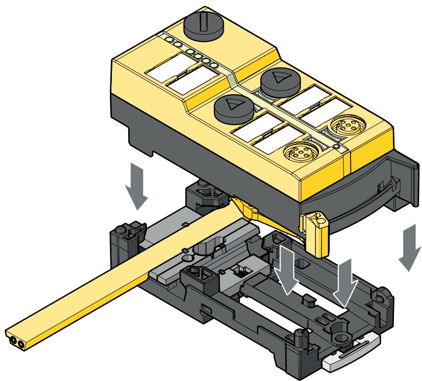
▶ Lock the device.

With the supplied lower part the flat cable can be aligned in three directions. Insert the flat cable guide for the required direction.


Settings at the lower part
▶ Select the required orientation of the flat cable - Position 1, 2 or 3.
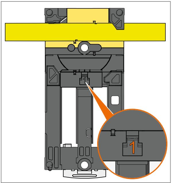
Fig. 3: Factory setting

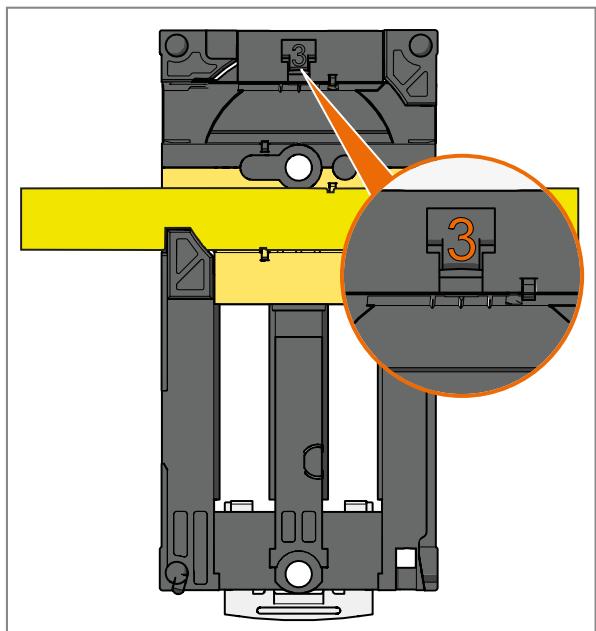
Settings at the upper part
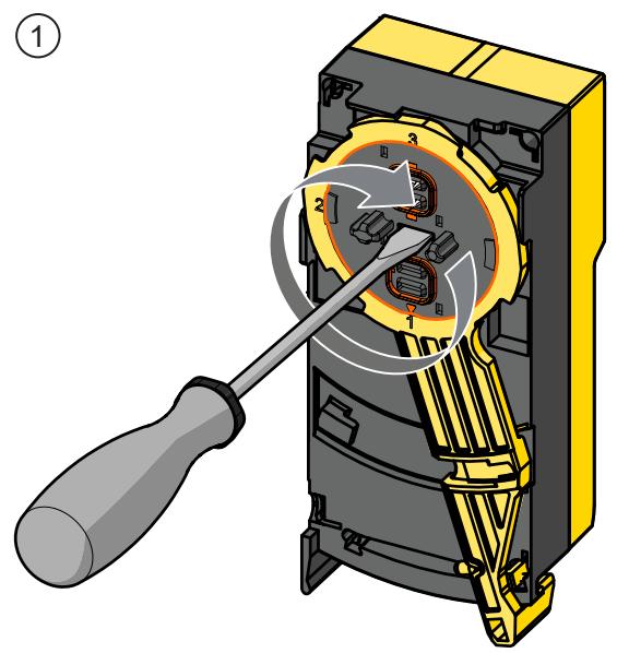
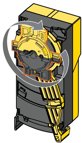
▶ Set the selected position at the upper part.
▶ Rotate the triangle to the corresponding number (image 1 and 2).

▶ Use a tool, e.g. a screwdriver (image 1) or the yellow-black flat cable guide (image 2).
②
▶ Take care in laying the AS-i flat cable, it should be laid straight for about 15 cm.
7.1 General notes on wiring
The threaded connections in the device correspond to the M12 standard. To ensure compliance with the specified protection rating, only cables that comply with this standard may be used. In the case of self-assembled cables, the system manufacturer is responsible for the protection rating.
▶ Use connectors with gold-plated contacts.
▶ During installation, place the connectors vertically so that the coupling nut will not damage the thread.
▶ Observe the coding of the connectors during installation.
If sockets in the device:
▶ Tighten the cable plug using 0.6...0.8 Nm.
▶ Cover unused connections with protective covers. Tightening torque: 0.6...0.8 Nm
Cover the addressing interface using the supplied protective cap. Tightening torque 0.6...0.8 Nm.
▶ Provide all outgoing cables with suitable strain relief after a maximum of 200 mm. Observe the minimum bending radius of the cables ( → information from the cable manufacturer).
The IP rating of the overall system depends on the protection ratings of the individual devices, the applied connection elements and the corresponding protective caps.
Attach a flat cable seal if the module is at the end of the cable line (to be ordered separately).
ATTENTION
No protection rating / no protection of the contacts without mounted connectors / protective caps.
▷ Inadmissible soiling / moisture possible.
▶ Before installation / when replacing the device, observe pollution degree 2.
7.2 Removing the connector with vibration protection
▶ Press the connector against the unit and simultaneously loosen the coupling nut.
8 Electrical connection

The unit must be connected by a qualified electrician.
Observe the national and international regulations for the installation of electrical equipment.
Voltage supply according to SELV, PELV.
▶ Disconnect power.
▶ Disconnect any independently supplied relay load circuits, if necessary.

Do not connect inputs and outputs to an external potential.
8.1 Pin assignment
| M12 socket 1 (receiver) | Pin | |
 | Supply +24 V | 1 |
| OSSD2 | 2 | |
| Supply 0 V | 3 | |
| OSSD1 | 4 | |
| FE | 5 |
| M12 socket 2 | Pin | |
 | n.c. (not used) | 1 |
| O-4 | 2 | |
| Supply 0 V | 3 | |
| O-3 | 4 | |
| n.c. (not used) | 5 |
| M12 socket 3 (transmitter) | Pin | |
 | Supply +24 V | 1 |
| 0 V | 2 | |
| Supply 0 V | 3 | |
| Supply + 24 V test | 4 | |
| FE | 5 |
| M12 socket 4 | Pin | |
 | n.c. (not used) | 1 |
| n.c. (not used) | 2 | |
| Supply 0 V | 3 | |
| O-4 | 4 | |
| n.c. (not used) | 5 |
The pin connection of the "transmitter" socket on the module allows the protected area width of an ESPE (electro-sensitive protective equipment) to be set to "range high".
The configuration signal on the AS-i module for setting the protected area width is not safety-related.
If the protected area width is to be set to "range low", use an EY3092 adapter cable which can be ordered separately.
ESPE receivers usually have an 8-pole M12 connector.
Use an adapter cable for connection to a 5-pole M12 socket. The EY3090 adapter cable which can be ordered separately is rated for the automatic operating mode of the ESPE.
8.2 Functional earth
 | Functional earthing tasks and applications |
| Functional earthing improves electromagnetic compatibility Discharge of interference currents Establishing a common reference potential Connection of shields to this potential |
8.3 Wiring examples
Connection of light grids or light curtains

1: Socket 3
3: Transmitter
2: Socket 1
4: Receiver
Connection of a laser scanner

1: Socket 3
2: Socket 1
3: Laser scanner
Connection of a fail-safe inductive sensor
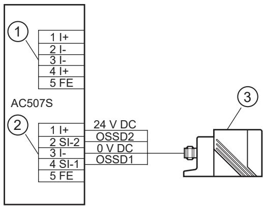
1: Socket 3
2: Socket 1
3: Fail-safe inductive sensor
8.4 Electronic contacts
The safe inputs correspond to type 2 digital inputs of EN 61131-2.
The electronic switching contacts are connected via the SI-1/2 socket.
The device supports the connection of fail-safe electronic sensors with 2 OSSD outputs. The duration of the switch-off test pulses of electronic sensors must not be longer than 1 ms.
Ensure a safe separation between the external LED and the normally closed contact. In the configuration software for the safety monitor the monitoring modules can be used as dual-channel positively guided module, dual-channel dependent module and dual-channel dependent module with filtering.
Do not connect any of the pins to an external potential since they are electrically connected to the AS-i cable.
The wiring influences the achievable Performance Level PL or the Safety Integrity Level SIL. The requirements for Performance Level d to ISO 13849-1 or SIL 2 to IEC 61508 are met.
Performance Level e according to ISO 13849-1 or SIL 3 to 61508 can be reached if both outputs of the protective equipment feature cross-fault monitoring.
If the protective equipment does not provide this feature, the cabling between the contacts to be monitored and the module must be selected in a way to exclude cross faults between the wires (see ISO 13849-2).
9 Operating and display elements

1: Addressing interface
2: 4 M12 sockets
3: LEDs
4: Labels
5: Transmitter
9.1 Troubleshooting
The LEDs of the safe AS-i module indicate faulty operating states.
10 Parameter setting
10.1 Addressing
▶ Address the module via the AC1154 addressing unit.

When mounted and wired the module can be addressed with an addressing cable via the integrated addressing interface.
▶ Assign a free address between 1 and 31.
The address is set to 0 at the factory.
11 Operation
▶ Avoid build-up of dirt and dust on the upper and lower parts so that the locking mechanism is not affected.

1: PWR LED, green
2: FAULT LED, red
3: O1... O4 output LEDs
4: Input LEDs, yellow
O1, O2 alarm LEDs, red
O3, O4 signal output LED, yellow
| LED designation | LED state | Colour | Operating status |
| FAULT | flashes | red | peripheral fault, e.g. overload or short circuit of the sensor supply |
| on | red | AS-i communication error, slave does not participate in the "normal" exchange of data, e.g. slave address 0 | |
| PWR | off | green | no voltage |
| on | green | voltage supply OK | |
| Alarm O1, O2 | on | red | alarm outputlogic state of the alarm LED outputs O1 and O2 |
| Signal output O3, O4 | on | yellow | signal outputlogic state of the signal outputs O3 and O4 |
| Input | off | yellow | safety contact opened |
| on | yellow | safety contact closed |

LED indications are no safe information.

Overload and short circuit of the input and output are signalled to the AS-i master (from version 2.1) via the “peripheral fault” flag in the status register.
11.1 Data bits
| Data bit | D3 | D2 | D1 | D0 |
| Input | SI-2 | SI-2 | SI-1 | SI-1 |
| Output | Output O-4 | Output O-3 | LED alarm O-2 | LED alarm O-1 |
The output bits D0... D3 are intended for signalling. Bits D0 and D1 have effect on the red alarm LEDs on the front panel (O-1, O-2) and can be used for signalling directly on the module.
Bits D2 and D3 have effect on the switching outputs O-3 and O-4 and can be used for external alarm LEDs, e.g. muting function blocks.

WARNING
Ensure safe separation between the safety-related NC contact circuit and the connections of the external alarm LED.
▷ Observe all notes on installation and handling in these instructions.
▶ The device must only be used under the specified operating conditions and in accordance with use as prescribed.
| Activated input channel | Bit sequence D3-D0 |
| SI-1 | XX00 |
| SI-2 | 00XX |
| SI-1 and SI-2 | 0000 |
| None | XXXX |
| Activated alarm output | Bit sequence D3-D0 |
| O-1 | XXX1 |
| O-2 | XX1X |
| Activated output channel | Bit sequence D3-D0 |
| O-3 | X1XX |
| O-4 | 1XXX |
X = random
The code words 0000, XX00 and 00XX cause the AS-i safety monitor to bring the installation into the safe state.
For more details on the effect of the data bits on the transmission sequence refer to the configuration software manual ASIMON (chapter Monitoring devices).
11.2 Parameters
The module allows the current module parameters to be read and informs which of the two switching contacts to be connected was opened during the demand on the safety function.

This parameter information is not part of the safe AS-i transmission and should not be treated as safe data transmission.
It must in no case be linked with any safety functions nor evaluated in this context.
Assignment of the parameter bits
| Parameter bit | P0 | P1 | P2 | P3 |
| Switching contact socket | SI-1 | SI-2 | not used | not used |
Meaning of the logic states P0... P3
1: Contact closed
0: Contact open
11.3 Response times
The response time of the safe AS-i module for a safety demand is max. 10 ms. For the calculation of the response time of the complete system the response times of the other components also have to be added (mechanical contacts, safety monitor and external relays or contactors possibly connected to the safety monitor output).
12 Technical data
AC507S
Safe AS-Interface Classic
Line module with quick mounting technology
ClassicL 2SI 2DOT 2LO OSSD


Application
| Design | housing for DIN rail mounting |
| Application | AS-i Safety at Work |
Electrical data
| Operating voltage | [V] | 26.5...31.6 DC; ("supply class 2" to cULus) |
| Max. current consumption from AS-i | [mA] | 280 |
| Protection class | III | |
| Reverse polarity protection | yes; (AS-i) | |
| Reverse polarity protection | yes | |
| Max. current load per module/slot | [A] | 0.2 |
| Integrated watchdog | yes |
Inputs / outputs
| Number of inputs and outputs | Number of digital inputs: 2; Number of digital outputs: 2 |
Inputs
| Number of digital inputs | 2; (2 x safety input) | |
| Input circuit of digital inputs | PNP | |
| Sensor supply of the inputs | AS-i | |
| Power supply | [V] | 19.2...30 |
| Max. total current rating of inputs | [mA] | 200 |
| Input current limitation | [mA] | 8 |
| Input current High | [mA] | >6 |
AC507S
Safe AS-Interface Classic
Line module with quick mounting technology

ClassicL 2SI 2DOT 2LO OSSD
| Input current Low | [mA] | < 2 |
| Switching level high | [V] | >11 |
| Switching level low | [V] | < 5 |
| Overload protection digital inputs | yes | |
| Short-circuit detection | yes | |
| Cross-fault monitoring | no | |
| Short-circuit proof | yes |
Outputs
| Output signal | switching signal | |
| Number of digital outputs | 2 | |
| Voltage range DC | [V] | 18...28.8; (AS-i) |
| Max. current load per output | [mA] | 50 |
| Short-circuit protection | yes | |
| Short-circuit proof | yes | |
| Overload protection | yes | |
| Electrically separated | no | |
| Actuator supply outputs | AS-i | |
Operating conditions
| Ambient temperature [°C] | -25...55 | |
| Note on ambient temperature | with switched outputs: -25...40 °C | |
| Max. relative air humidity [%] | 95 | |
| Max. height above sea level [m] | 2000 | |
| Protection | IP 67 | |
| Pollution degree | 2 | |
Tests / approvals
| EMC | EN 62026-2 | |
| EN 61326-3-1 | ||
| Shock resistance | EN 60068-2-27 | |
| Vibration resistance | EN 60068-2-6 |
Safety classification
| Complies with the requirements | ISO 13849-1 category 4, PL e |
| IEC 61508 SIL 3 | |
| Mission time TM (additional indication) | 20 years |
| PFH [1/h] | 2,33E-11 |
AS-i classification
| AS-i version | 2.11; 3.0 | |
| AS-i addressing | addressing socket | |
| Extended addressing mode | no | |
| AS-i master profile | M3; M4 | |
| AS-i profile | S-7. B. E | |
| AS-i I/O configuration | [hex] | 7 |
| AS-i ID code | [hex] | B. E |
| AS-i certificate | 126301 | |
AC507S
Safe AS-Interface Classic
Line module with quick mounting technology

ClassicL 2SI 2DOT 2LO OSSD
| Assignment of the data bits | data bit | D0 | D1 | D2 | D3 |
| assignment | O1 | O2 | O3 | O4 |
Mechanical data
| Weight [g] | 294.5 |
| Housing | rectangular |
| Type of mounting | AS-i flat cables directly connectable; mounting on DIN rail; (TH35 (EN 60715)) |
| Dimensions [mm] | 103 x 45 x 44.7 |
| Materials | housing: PA; piercing contacts: CuSn6 nickel-plated and tin-plated |
Displays / operating elements
| Display | operation | 1 x LED, green |
| errors | 1 x LED, red | |
| switching status | 1 x LED, yellow | |
| alarm | 1 x LED, red |
Electrical connection
| Module connection | Flat cables |
Accessories
| Items supplied | lower part |
| Accessories (optional) | Addressing cable:, E70213 |
| Protective cap: M12, E73004 |
Remarks
| Remarks | PL e, cat. 4, SIL 3 only if the fault exclusions described in the manual are used |
| Pack quantity | 1 pcs. |
Electrical connection
quick mounting technology for AS-i flat cable: ; three orientations possible
Electrical connection - O-3/4
Connector: 1 x M12; coding: A; Maximum cable length: 10 m

| 1 | n.c. | |
| 2 | O-4 | |
| 3 (I-) | L- | |
| 4 | O-3 | |
| 5 | n.c. |
AC507S
Safe AS-Interface Classic
Line module with quick mounting technology
ClassicL 2SI 2DOT 2LO OSSD

Electrical connection - O-4
Connector: 1 x M12; coding: A; Maximum cable length: 10 m

| 1 | n.c. |
| 2 | n.c. |
| 3 (I-) | L- |
| 4 | |
| 5 | n.c. |
Electrical connection - SI-1/2
Connector: 1 x M12; coding: A; Maximum cable length: 10 m

| 1 (I+) | L+ | |
| 2 | SI-2 | |
| 3 (I-) | L- | |
| 4 | SI-1 | |
| 5 | FE |
Electrical connection - Trans
Connector: 1 x M12; coding: A; Maximum cable length: 10 m

| 1 (I+) | L+ |
| 2 (I-) | L- |
| 3 (I-) | L- |
| 4 (I+) | L+ |
| 5 | FE |
FE: functional earth; n.c.: not used
13 Approvals / certificates
• EU Declaration of Conformity
- TÜV Rheinland
- AS-Interface
- UL (cULus)
Supply the device via an appropriate class 2 source so that the supply class requirements in accordance with UL 508 are met.
14 Maintenance, repair and disposal
If used correctly, the unit is maintenance-free.
The device must only be repaired by the manufacturer. Observe the safety instructions ( → Safety instructions).
▶ After use, dispose of the unit in an environmentally friendly way in accordance with the applicable national regulations.
- 1 PRELIMINARY NOTE
- 1.1 SYMBOLS USED
- 1.1.1 SAFETY SYMBOL ON THE DEVICE
- 1.2 WARNINGS
- 2 SAFETY INSTRUCTIONS
- 2.1 SAFETY-RELATED REQUIREMENTS REGARDING THE APPLICATION
- 3 TRANSPORT, HANDLING AND STORAGE
- 4 ITEMS SUPPLIED
- 5 INTENDED USE
- 6 FUNCTION DESCRIPTION
- 7 INSTALLATION
- 7.1 GENERAL NOTES ON WIRING
- 7.2 REMOVING THE CONNECTOR WITH VIBRATION PROTECTION
- 8 ELECTRICAL CONNECTION
- 8.1 PIN ASSIGNMENT
- 8.2 FUNCTIONAL EARTH
- 9 OPERATING AND DISPLAY ELEMENTS
- 9.1 TROUBLESHOOTING
- 10 PARAMETER SETTING
- 10.1 ADDRESSING
- 11 OPERATION
- 11.1 DATA BITS
- 11.2 PARAMETERS
- 11.3 RESPONSE TIMES
- 12 TECHNICAL DATA
- 13 APPROVALS / CERTIFICATES
- 14 MAINTENANCE, REPAIR AND DISPOSAL
Brand : IFM
Model : AC505S
Category : Sensor