USER MANUAL Promig 400 G DV WS GYS
FR 2-9/58-76
EN 10-17 / 58-76
DE 18-25/58-76
ES 26-33 / 58-76
RU 34-41 / 58-76
NL 42-49/58-76
IT 50-57/58-76
PROMIG 400-4S PROMIG 400 G DV PROMIG 400-4S DUO DV PROMIG 400-4S DV WS PROMIG 400 G DV WS

AVERTISSEMENTS - RÉGLES DE SECURITÉ
CONSIGNÉGÉRALE

MODE "MANUEL" (FIG-V)
Read and understand the following safety recommendations before using or servicing the unit. Any change or servicing that is not specified in the instruction manual must not be undertaken.
The manufacturer is not liable for any injury or damage due to non-compliance with the instructions featured in this manual. In the event of problems or uncertainty, please consult a qualified person to handle the inspection properly.
ENVIRONMENT
This equipment must only be used for welding operations in accordance with the limits indicated on the descriptive panel and/or in the user manual. The operator must respect the safety precautions that apply to this type of welding. In case of inadequate or unsafe use, the manufacturer cannot be held liable for damage or injury.
This equipment must be used and stored in a place protected from dust, acid or any other corrosive agent. Operate the machine in an open, or well-ventilated area.
Operating temperature:
Use between -10 and +40^ (+14 and +104°F).
Store between -20 and +55°C (-4 and 131°F).
Air humidity:
Lower or equal to 50% at 40°C (104°F).
Lower or equal to 90% at 20°C (68°F).
Altitude:
Up to 1000 meters above sea level (3280 feet).
PROTECTION OF THE INDIVIDUALS
Arc welding can be dangerous and can cause serious and even fatal injuries.
Welding exposes the user to dangerous heat, arc rays, electromagnetic fields, noise, gas fumes, and electrical shocks. People wearing pacemakers are advised to consult with their doctor before using this device.
To protect oneself as well as the other, ensure the following safety precautions are taken:

In order to protect you from burns and radiations, wear clothing without cuffs. These clothes must be insulated, dry, fireproof and in good condition, and cover the whole body.

Wear protective gloves which guarantee electrical and thermal insulation.

Use sufficient welding protective gear for the whole body: hood, gloves, jacket, trousers... (varies depending on the application/ operation). Protect the eyes during cleaning operations. Do not operate whilst wearing contact lenses. It may be necessary to install fireproof welding curtains to protect the area against arc rays, weld spatters and sparks. Inform the people around the working area to never look at the arc nor the molten metal, and to wear protective clothes.

Ensure ear protection is worn by the operator if the work exceeds the authorised noise limit (the same applies to any person in the welding area).
Stay away from moving parts (e.g. engine, fan...) with hands, hair, clothes etc...
Never remove the safety covers from the cooling unit when the machine is plugged in - The manufacturer is not responsible for any accident or injury that happens as a result of not following these safety precautions.
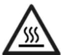
The pieces that have just been welded are hot and may cause burns when manipulated. During maintenance work on the torch or the electrode holder, you should make sure it's cold enough and wait at least 10 minutes before any intervention. The cooling unit must be on when using a water cooled torch in order to ensure that the liquid does not cause any burns.
ALWAYS ensure the working area is left as safe and secure as possible to prevent damage or accidents.
WELDING FUMES AND GAS

The fumes, gases and dust produced during welding are hazardous. It is mandatory to ensure adequate ventilation and/or extraction to keep fumes and gases away from the work area. An air fed helmet is recommended in cases of insufficient air supply in the workplace.
Check that the air intake is in compliance with safety standards
Care must be taken when welding in small areas, and the operator will need supervision from a safe distance. Welding certain pieces of metal containing lead, cadmium, zinc, mercury or beryllium can be extremely toxic. The user will also need to degrade the workpiece before welding. Gas cylinders must be stored in an open or ventilated area. The cylinders must be in a vertical position secured to a support or trolley. Do not weld in areas where grease or paint are stored.
FIRE AND EXPLOSIONS RISKS

Protect the entire welding area. Compressed gas containers and other inflammable material must be moved to a minimum safe distance of 11 meters.
A fire extinguisher must be readily available.
Be careful of spatter and sparks, even through cracks. It can be the source of a fire or an explosion.
Keep people, flammable objects and containers under pressure at a safe distance.
Welding of sealed containers or closed pipes should not be undertaken, and if opened, the operator must remove any inflammable or explosive materials (oil, petrol, gas...).
Grinding operations should not be directed towards the device itself, the power supply or any flammable materials.
GAS BOTTLE

Gas leaking from the cylinder can lead to suffocation if present in high concentrations around the work area.
Transport must be done safely: Cylinders closed and product off. Always keep cylinders in an upright position securely chained to a fixed support or trolley.
Close the bottle after any welding operation. Be wary of temperature changes or exposure to sunlight.
Cylinders should be located away from areas where they may be struck or subjected to physical damage.
Always keep gas bottles at a safe distance from arc welding or cutting operations, and any source of heat, sparks or flames.
Be careful when opening the valve on the gas bottle, it is necessary to remove the tip of the valve and make sure the gas meets your welding requirements.
ELECTRIC SAFETY

The machine must be connected to an earthed electrical supply. Use the recommended fuse size.
An electrical discharge can directly or indirectly cause serious or deadly accidents .
Do not touch any live part of the machine (inside or outside) when it is plugged in (Torches, earth cable, cables, electrodes) because they are connected to the welding circuit.
Before opening the device, it is imperative to disconnect it from the mains and wait 2 minutes, so that all the capacitors are discharged.
Do not touch the torch or electrode holder and earth clamp at the same time.
Damaged cables and torches must be changed by a qualified and skilled professional. Make sure that the cable cross section is adequate with the usage (extensions and welding cables). Always wear dry clothes in good condition, in order to be insulated from the electrical circuit. Wear insulating shoes, regardless of the environment in which you work in.
EMC CLASSIFICATION

These Class A devices are not intended to be used on a residential site where the electric current is supplied by the public network, with a low voltage power supply. There may be potential difficulties in ensuring electromagnetic compatibility on these sites, because of the interferences, as well as radio frequencies.
This equipment complies with EN 61000-3-12, provided that the power of the short-circuit Ssc is equal to or greater than 3.9MVA at the interface between the machine and the mains power network. It is the responsibility of the installer or user of the equipment to ensure if necessary by consulting the operator of the mains electricity, that the equipment is only connected to a power supply where the power of short-circuit ssc is equal to or greater than 3.9 MVA.
This equipment complies with the CEI 61000-3-11 standard.
ELECTROMAGNETIC INTERFERENCES
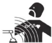
The electric currents flowing through a conductor cause electrical and magnetic fields (EMF). The welding current generates an EMF field around the welding circuit and the welding equipment.
The EMF fields may disrupt some medical implants, such as pacemakers. Protection measures should be taken for people wearing medical implants. For example, access restrictions for passers-by or an individual risk evaluation for the welders.
All welders should take the following precautions in order to minimise exposure to the electromagnetic fields (EMF) generated by the welding circuit:
- position the welding cables together - if possible, attach them;
- keep your head and torso as far as possible from the welding circuit;
- never enroll the cables around your body;
- never position your body between the welding cables. Hold both welding cables on the same side of your body;
- connect the earth clamp as close as possible to the area being welded;
- do not work too close to, do not lean and do not sit on the welding machine
- do not weld when you're carrying the welding machine or its wire feeder.

People wearing pacemakers are advised to consult their doctor before using this device.
Exposure to electromagnetic fields while welding may have other health effects which are not yet known.
RECOMMANDATIONS TO ASSES THE AREA AND WELDING INSTALLATION
Overview
The user is responsible for installing and using the arc welding equipment in accordance with the manufacturer's instructions. If electromagnetic disturbances are detected, it is the responsibility of the user of the arc welding equipment to resolve the situation with the manufacturer's technical assistance. In some cases, this remedial action may be as simple as earthing the welding circuit. In other cases, it may be necessary to construct an electromagnetic shield around the welding power source and around the entire piece by fitting input filters. In all cases, electromagnetic interferences must be reduced until they are no longer bothersome.
Welding area assessment
Before installing the machine, the user must evaluate the possible electromagnetic problems that may arise in the area where the installation is planned.
In particular, it should consider the following:
a) the presence of other power cables (power supply cables, telephone cables, command cable, etc...) above, below and on the sides of the arc welding machine.
b) television transmitters and receivers;
c) computers and other hardware;
d) critical safety equipment such as industrial machine protections;
e) the health and safety of the people in the area such as people with pacemakers or hearing aids;
f) calibration and measuring equipment
g)The isolation of the equipment from other machinery.
The user will have to make sure that the devices and equipments that are in the same room are compatible with each other. This may require extra precautions;
h) make sure of the exact hour when the welding and/or other operations will take place.
The surface of the area to be considered around the device depends on the building's structure and other activities that take place there. The area taken in consideration can be larger than the limits determined by the companies.
Welding area assessment
Besides the welding area, the assessment of the arc welding systems installation itself can be used to identify and resolve cases of disturbances. The assessment of emissions must include in situ measurements as specified in Article 10 of CISPR 11. In situ measurements can also be used to confirm the effectiveness of mitigation measures.
RECOMMENDATION ON METHODS OF ELECTROMAGNETIC EMISSIONS REDUCTION
a. National power grid: The arc welding machine must be connected to the national power grid in accordance with the manufacturer's recommendation. If interferences occur, it may be necessary to take additional preventive measures such as the filtering of the power supply network. Consideration should be given to shielding the power supply cable in a metal conduit. It is necessary to ensure the shielding's electrical continuity along the cable's entire length. The shielding should be connected to the welding current's source to ensure good electrical contact between the conduct and the casing of the welding current source.
b. Maintenance of the arc welding equipment: The arc welding machine should be submitted to a routine maintenance check according to the manufacturer's recommendations. All accesses, service doors and covers should be closed and properly locked when the arc welding equipment is on.. The arc welding equipment must not be modified in any way, except for the changes and settings outlined in the manufacturer's instructions. The spark gap of the arc start and arc stabilization devices must be adjusted and maintained according to the manufacturer's recommendations.
c. Welding cables: Cables must be as short as possible, close to each other and close to the ground, if not on the ground.
d. Electrical bonding : consideration should be given to bonding all metal objects in the surrounding area. However, metal objects connected to the workpiece increase the risk of electric shock if the operator touches both these metal elements and the electrode. It is necessary to insulate the operator from such metal objects.
e. Earthing of the welded part : When the part is not earthed - due to electrical safety reasons or because of its size and its location (which is the case with ship hulls or metallic building structures), the earthing of the part can, in some cases but not systematically, reduce emissions It is preferable to avoid the earthing of parts that could increase the risk of injury to the users or damage other electrical equipment. If necessary, it is appropriate that the earthing of the part is done directly, but in some countries that do not allow such a direct connection, it is appropriate that the connection is made with a capacitor selected according to national regulations.
f. Protection and plating : The selective protection and plating of other cables and devices in the area can reduce perturbation issues. The protection of the entire welding area can be considered for specific situations.
TRANSPORT AND TRANSIT OF THE WELDING MACHINE

Do not use the cables or torch to move the machine. The welding equipment must be moved in an upright position.
Do not place/carry the unit over people or objects.
Never lift the machine while there is a gas cylinder on the support shelf. A clear path is available when moving the item.
The removal of the wire reel from the machine is recommended before undertaking any lifting operation.

Stray welding currents/voltages may destroy earth conductors, damage electrical equipment or cause components to warm up which may cause a fire.
- All welding connections must be firmly secured, check regularly!
- Check that the metal piece fixation is strong and without any electrical problems !
- Attach or hang all the electrically conductive elements, such as the trolley in order to insulate them
- Do not place any electrical equipment such as drills on top of the welding machine without insulating them !
- Always place welding torches or electrodes holders on an insulated surface when they're not in use !
EQUIPMENT INSTALLATION
- Put the machine on the floor (maximum incline of 10^ .)
- Ensure the work area has sufficient ventilation for welding, and that there is easy access to the control panel.
- The machine must not be used in an area with conductive metal dusts.
- The machine must be placed in a sheltered area away from rain or direct sunlight.
- The machine protection level is IP21, which means :
- Protection against access to dangerous parts from solid bodies of a ≥ 12.5mm diameter and,
- Protection against vertically falling drops.
The power cables, extensions and welding cables must be fully uncoiled to prevent overheating.

The manufacturer does not incur any responsibility regarding damages to both objects and persons that result from an incorrect and/or dangerous use of the machine.
MAINTENANCE / RECOMMENDATIONS


- Maintenance should only be carried out by a qualified person. Annual maintenance is recommended.
- Ensure the machine is unplugged from the mains, and wait for two minutes before carrying out maintenance work. DANGER High Voltage and Currents inside the machine.
- Remove the casing 2 or 3 times a year to remove any excess dust. Take this opportunity to have the electrical connections checked by a qualified person, with an insulated tool.
- Regularly check the condition of the power supply cable. If the power cable is damaged, it must be replaced by the manufacturer, its after sales service or an equally qualified person.
- Ensure the ventilation holes of the device are not blocked to allow adequate air circulation.
- Do not use this equipment to thaw pipes, to charge batteries, or to start any engine.
INSTALLATION (FIG-I) - PRODUCT OPERATION
DESCRIPTION
In order to get the maximum from this machine, please read the following instructions:
The Promig is a «synergic» semi-automatic welding unit, for welding (MIG or MAG). It is recommended for welding steel, stainless steel and aluminium. Adjustment is quick and easy with the « synergic wire speed » function. It works on 3-phase 400V (or on 230V
- 3 phase for the DV models as well.)
To operate, the PROMIG :
- 400 G DV must be used with the external wire feeder TF-4RN (ref. 061699) and an interconnect cable.
- 400 DUO DV must be used with the external wire feeder TF-4RN (ref. 061699) and an interconnect cable.
- 400 G DV WS must be used with the external wire feeder TF-4W (ref. 061705) and an interconnect cable.
POWER SUPPLY
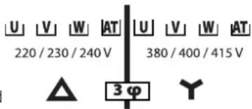
The welders are fitted with a 32 A socket type EN 60309-1 which must be connected to a three-phase 400V (50 - 60 Hz) power supply fitted with four wires and one earthed neutral. The absorbed effective current (I1eff) is displayed on the machine, for optimal use. Check that the power supply and its protection (fuse and/or circuit breaker) are compatible with the current needed by the machine. In some countries, it may be necessary to change the plug to allow the use at maximum settings.
Power supply 3-phase 230V for the Promig 400 G DV, 400 DUO DV, 400 DV WS et 400 G DV WS:
WARNING: these devices are pre-assembled at the factory on 3-phase 400V. If your electrical installation is on 3-phase 230V amend the connections on the terminal block inside the product. This operation must be done by a qualified person. Please see the electrical diagram 230V located inside the product. The power supply must be protected by a 25A circuit breaker and a 30mA differential.
DEVICE PRESENTATION (FIG-II)
1- On - off switch of the generator
2-Voltage adjustment switch
3- Keyboard for setting welding parameters (manual or automatic mode).
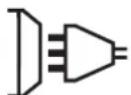
4- Torch connection according to European standard.
5- Thermal protection indicator on the control keypad: indicates a thermal break when the device is used intensively (several minutes shutdown).
6- Front headlamp holder
7- Ground clamp output
8-Bottle holder (max. one 10m3 bottle).
9-Coil support 200/300 mm.
10-Gas inlet 1 of the integrated reel (400-4S and 400-4S DUO)
11- Rear cable support.
12-Gas inlet 2 of the separate reel (400-4S DUO and 400 G)
13-Gas outlet 2 of the separate reel (400-4S DUO and 400 G)
14- Separate reel control connector
(400-4S DUO and 400 G)
15- Separate reel power connector
(400-4S DUO and 400 G)
16- Thread speed potentiometer selection switch (only on 400 G DV)
PROMIG 400-4S WS and 400 G DV WS :
17- On/off switch for the cooling unit
18- Cooling unit fuse holder
19- Water connections of the connecting harness (400 G DV WS)
20-Water connections of the torch (400-4S WS)
SEMI-AUTOMATIC FOR STEEL/STAINLESS STEEL (MAG MODE) (FIG III)
The Promig 400 can weld 0.8 / 1mm and 1.2mm steel and stainless steel wires. The product is fitted to work with 1mm steel wire (roller 1 / 1,2) . For Steel or Stainless Steel, you will need to use a The product isfitted in standard to work with 0.8 steel wire. specific gas - Argon + CO2 (Ar + CO2). The proportion of CO2 will vary depending on usage. For the specific requirements, seek advice from your gas distributor. The gas flow in steel is between10 and 20L / min depending on the environment and experience of the welder.
SEMI-AUTOMATIC WELDING FOR ALUMINIUM
The Promig 400 can weld 1mm and 1.2mm aluminium wire. (FIG-III-B) To weld aluminium, inert gas "pure argon" (AR) is required. For specific requirements, seek advice from your gas distributor. The gas flow in aluminium should be between 15 and 25L / min depending on the environment and experience of the welder. Below, see the differences between steel welding and aluminium welding:
- Rollers pressure on the wire: put only the minimum pressure in order not to flatten the wire.
- Capillary tube : remove the capillary tube before connecting an aluminium torch (with teflon torch liner).
- Torch : using an aluminium torch. This torch has a teflon torch liner to reduce friction.
DO NOT cut the sheath near the connector ! The sheath guides the wire from the rollers. (FIG-III-B)
- Contact tip : use a SPECIAL aluminium contact tip to match the wire diameter.
REEL AND TORCH ASSEMBLY (FIG IV)
This product takes 0.200 / 300mm wire reel (ecological)
Open the door of the machine.
- Place the reel on the driving pin (3) of the reel support. To install a 200mm wire reel, fit an adaptor on the support (ref. 042889).
- Adjust the reel brake (4) to avoid the reel inertia tangling the wire when welding stops. Do not overtighten! Tighten the fixing screw (2).
- The electrical rollers (8) are double groove rollers ( 0, 8/ 1 or 1/2 ) and the indication on the visible side of the roller is the diameter in use. For a 0.1 ~mm wire, use the 0.1 groove. For the first use:
- Release the fixing screw which guides the wire (5)
- Fit the rollers, then tighten the screw retainer (9).
- Put the wire guide in place (7) as close as possible to the roller without contact, then tighten the fixing screw.
- To set the adjusting knob of the drive rollers (6), proceed as follows: Loosen the knob fully, start the motor by pressing the torch trigger, tighten the adjustment knob whilst pressing the trigger. Bend the wire where it comes out of the nozzle. Put a finger on the bended wire to avoid any movement. The setting is correct when the guide roller slides over the wire even when it is blocked at the end of the torch.
- Adjustment of the tension on the wire (6): on the scale 3-4 for steel and 2-3 for aluminium.
CHOICE OF REELS
Possible settings : maximum : 300 mm - 15 kg
*Make sure to have a teflon torch liner/contact tip for alu. Remove the capillary tube.
| Type fil Weight (kg) Ø fil (mm) Torch Gas | | | |
| steel | Ø 300 15 0.6 / Ø 8 / 1.0 / 1.2 x | | | argon + CO2 |
| Ø 200 5 0.6 / Ø 8 / 1.0 x | | |
| stainless steel | Ø 200 5 0.8 x | | |
| Alu AG5 | Ø 300 7 1.0 / Ø 2 x* | | | Pure argon |
| Ø 200 2 0.8 / Ø 1.2 x* | | |
GAS CONNECTION
Connect the manometer (flowmeter) to the gas bottle if needed, then connect the gos hose to the gas connector. To avoid gas leak, use collars supplied in the accessories box. Make sure the gas bottle hold in place respecting chain fastening cf. FIG-IV-1. Maximum gas pressure : 0.5 MPa (5 bars).
LIQUID COOLING (PROMIG 400 DV WS AND 400 G DV WS)
Connect the red and blue wire of the connecting harness from the generator.
Fill the tank up to its maximum. The cooling liquid recommended by GYS (ref. 052246), must be used. The use of any other cooling liquid, and especially the standard automobile liquid, can lead by electrolysis effect, to the accumulation of dumps in the cooling system, damaging it and even more by blocking the circuit.
Any damage caused to the machine by the use of another cooling liquid will not be taken under warranty.
The PROMIG 400 DV WS and 400 G DV WS can be operated with an air-cooled torch or a water-cooled torch.
For use with an air-cooled torch, do not activate the on/off switch on the cooling unit.
For use with a water-cooled torch, activate the on/off switch on the cooling unit.
PROMIG 400 DV WS and 400 G DV WS: NEVER USE YOUR UNIT WITHOUT COOLING LIQUID when the pump is working. Ensure liquid is at least minimum level (gauge at back of machine) Failure to adhere to this may result in irreparable damage to the cooling system, and machine.
Always respect the basic rules of welding.
- Do not block/cover the ventilation holes of the machine.
- Leave the device plugged in after welding to allow proper cooling down.
COMMAND KEYBOARD (FIG-V)
Choice of welding mode (2)
-NORMAL (2T) : standard welding 2T
-NORMAL (4T) : standard welding 4T
- SPOT : spot function, with adjustment of the spot diameter
Wire speed adjustment (4) Adjustment wire speed potentiometer. The speed varies from 1 to 20m / minute .
SPOT adjusting potentiometer (5): To adjust the welding time of a point, the size of the point and the time between each point.
Manual mode (1)
In manual mode, the wire speed is determined by the user by adjusting the potentiometer (2).
Synergic mode (3)
Position the potentiometer (4) in the centre of the zone «OPTIMAL SYNERGIC »
In this mode, the device determines the optimal wire speed according to 3 parameters:
-Voltage
- Wire diameter
- Wire type
It is still possible to adjust the wire speed + / - with the potentiometer (4).
MODE (FIG-V)
To set the machine, proceed as follows:
- Choose the welding voltage using the 2^*7 positions switch (depending on the product)
Example: position A-1 to weld 1 mm steel metal sheet with 0.8mm wire.
- Adjust the wire speed with the potentiometer(2).
MANUAL
m/min
In manual mode only, this function displays accurately the wire speed setting.
Advice:
The wire speed adjustment is often determined « based on sound »: the arc must be stable and have a minimal crackling. If the speed is too low, the arc is not continuous. If the speed is too high, the arc crackles and the wire pushes back the torch.
MODIFICATION OF FACTORY SETTINGS
The product manages the burn back and post gas. In manual mode, it is possible to adjust factory settings through the hidden menu. Enter the hidden mode by pressing the «MODE» button (2) for 3 seconds.
Move through the different functions with the «MODE» button (2).
F06: Burn back adjustment. This function enables to avoid the wire to stick to the contact tip at the end of your weld. The adjustment range of this product is between -10ms to 70ms with the buttons TYPE (-) and WIRE(+)
F07: Post gaz adjustment Adjustment on how long the gas protects the welding pool at the end of the weld. The adjustment range is between 0ms to 950ms with the buttons TYPE (-) and WIRE(+)
F08: In manual and synergic mode, Squeeze time adjustment. Adjustment of the wire speed before current detection: The adjustment range is between 50 and 120£ with the buttons TYPE (-) and WIRE (+) .
EXPERT SETTING (STANDARD EN 1090)
In order to comply with EN1090, the product supports WPS (Welding Procedure Specification) and helps to achieve WPQR (Welding Procedure Qualification Record). It is possible to calibrate the voltage, the current and the wire speed of the product. Warning: the calibration must be done by GYS or its qualified distributor. Required equipment : Dummy load (ref: 060418), tachometer, voltmeter and ammeter (ref: 053984).
1/ Voltage and current calibration:
The functions F00 (voltage) and F01 (current) are adjustable through the hidden menu. These functions are available by pressing the «MODE» button for 3 seconds. The setting range varies from -20% to +20%, by 1% step.
2/ Wire speed calibration:
WARNING: To display the wire speed, a calibration is required for each welding configuration.
The functions F02 (internal motor) and F05 (sparated wire feeder) are adjustable through the hidden menu (you can access it by pressing the MODE button for 3 seconds). The setting range varies from -20% to +20% , in 1% increments.
To exit hidden menus, move through the different functions with the MODE button until you see «END».
MODE (FIG-V)
With this function, there is no need to adjust the wire speed.
- Put the wire speed potentiometer (4) in the middle of the « Optimal synergic » zone. - Select:
-The wire type (3)
-The wire diameter (3)
- The power (switch on the front panel), to select the right position in accordance with the thickness of the part to weld, please refer to the table «Synergic mode» (fig. VI). From this combination, the device determines the optimal wire speed and the device is ready to weld. It is also possible to adjust the wire speed if necessary by adjusting the potentiometer (4) + or - manually. A memory of the latest welding configurations is made and is recalled each time the machine is switched on or each time a trigger of one of the torches is pressed.

The wire feeders contain moving parts that may catch hand, hair, clothes or tools which can lead to injuries! Take extra care.
- Do not place your hand on mobile/pivoting/wire feeding parts of the machine!
- Make sure that all panels remain closed when in use!
Do not wear gloves when setting up the wire and changing the wire reel.
ADVICE AND THERMAL PROTECTION
- The product must not be carried by its handles, torch supports or the upper panel but by the underside of the product. The gas bottle must not be attached to the product during movement.
- Respect the basic rules of welding.
- Ensure the ventilation holes of the device are not blocked to allow adequate air circulation.
- Leave the device connected after welding to allow cooling.
Thermal protection: The light turns on and the cooling duration is a couple of minutes influenced by the ambient temperature.
WARRANTY
The warranty covers faulty workmanship for 2 years from the date of purchase (parts and labour).
The warranty does not cover:
- Transit damage.
Normal wear of parts (eg.: cables, clamps, etc.).
- Damages due to misuse (power supply error, dropping of equipment, disassembling).
- Environment related failures (pollution, rust, dust).
In case of failure, return the unit to your distributor together with:
- The proof of purchase (receipt etc ...)
- A description of the fault reported

I3MeHeHnI pEmoHT, He yKa3aHHbIe B 3ToI INHCTpyKcUH, He DoJIxHbI 6bItb IpeIpnHrTbI.
IpnH3BODInTeH He HecET OTBeTCTBeHHOCTH 3a TpaBMbl N MaTePnAInhble NOBpeKDeHnC B83AHHbE C HECOTBeTCTByIOUm DaHHoN IHCTpyKuIN nCNoJIb3OBAHNem annapata.
B cnyuae npo6JIembl nnn comHeHH, 6paTntecb K BaIInHpOBAHHOMy npoeeCNOHaI y nI npaBnBHO rnoKIOUeHna.
OKPYXKAIOUJAR CPEDA
3To 6OpdyOBaHne doJIKHO 6bItb NCIOJIb3OBAHO NCKIIOHTeJIbHO IIN CBAPoOHbIX pa6OT, ORpAHuINBaIcB yKa3AHmIM 3AbODckO TabNtHnN INCTpyKUHN. Heo6XoIMo COJIIOAdTb DInpeKTINbbl No Mepam 6e30NaCHocTN. B CInyae HeaAeKBaTHoro INn ONaCHO rCIOJIb3OBAHnN npOn3BOITeNB He HecET OTBETCTBeHHOCTN.
Annapa doJnKeH 6bTb yCTaHOBHeN B nOmeueHn 6e3 nbIn, KNCIObl, BO3rpoaMbx ra3OB, ININ dpynx Koppo3nHbIX BeueCTB. TaKne xe ycobnA doJXh b6tbc6JIIOeHbI IER eO xpaHHeN. Y6eINTEcB B pncyTcbN BEHTnlaun npn cnoJb3ObaHN annapata.
TempepaTpyHbI npedenbl:
IcnoIb3OBAHHe:OT-10do +40^ (OT+14do +104^
XpaHHeHne:OT-20do +55^ (OT-4do 131^
BlaXHoCTb Bo3Dyxa:
50% INI HIXe npn 40°C (104°F).
90% niiHnke npu 20^ (68^)
BbCota Hau ypoBHeM Mopr:
1000M BbICOTbHn yPobHem MOpA (3280 cyTOB).
HINBnDyAJIbHA3AUHTA N 3AUHTA OKPYXEHNIA
DyroBa CBapKa MoKet 6bITb ONaCHO N Bb3BaTb TReKeIbe I DaKe CMePTeNbHbIe paHeHnA.
CbapouhIbe pa6oTbIOBnBepraHOT noB3OBaTeJIa BO3JeCTBnIO ONaCHO IOCTOHNa TEIIa, CBETOBORIO 3NJyEHINr DYIN, 3JNEKTPOMarHHTbIX NOJIe (oc6oe BHMmaHe IInzam, IMeHOUIm 3JKeKTPOKApDIOCTMMyIaTOp), CInbHOMy WIMy, BbIDENHmR r3a, a TAKKe MOrYr CTaTB npuHOnnopaxhenr 3JNEKTPnuecknM TOKOM.
YTo 6bI npabInbNo 3aunTntB ce6n 3aunTntB okpykaiox, co6nloaTe cneDyioane npabIna 6e0nachoctn:

TTO6b3aunntbce6oT OXOROB nO6nyehn npna paoTe cannapaTOM, HadeBaTe cyxuipo a6oyu 3aunTHyo OeKdy (B XopoWem coCTOHN) n3 orHeynopHOn TKAHN, 6e3 OTBOPOTOB, KOtopa IOKpbIbaet NIOHOCTbIO BCE TENo.

Pa6oTaIeB 3aunTHbIX pyKaBauCax, o6ecneuBaIOUne 3JeKtpo- n TepMoOn3OJaUIO.

NcnoB3ynte cpeCTBa 3aunTbI nI CBAKP N/INI WEM dI CBAPK COOTBETCTBYOero yPOBn3AunTBI (B 3ABNCMOCTN OT nCNoB3OBAHn). 3aunTIte rna3 npn onepauix OCHTKn. HoWeHne KOHTaKTHbIX INH3 BOCnPueaETcR.
B HeKOTOpbix Cnyaex Heo6xOIMMo OkpyKINb 30Hy OrHeyIopHbIMN 7TOPAMN, YTO6bl 3aunTnTB 30Hy CBAPKn OT Lyuei, 6pb13r HakaJIeHHoro WJnaka.
IpeDynpedite Okpykaioux He cMOTpeb Ha dyu no6pa6aTbBaembe deTaJn Hn HaeBaTb 3aunTHyo pa6ooyo oJeKny.

Hocnte HauuHnKn npOTNB lyma, eCNI CBAPoUhB II pOuceCIOCTnraeT 3ByKOBOrO yPOBnB BIIe DO3BOJeHHORO (3TO JxE OTHOCNTcKo BCem IInzam, HaxoJyMmCB B3OHe CBAPKn).
OueHka CBapouHoY yCTaHOBKn
POMIMO OueHKN 30HbI, oueHKa annapaTOB pyHOn dyROB CBAPKn MOKeT nOmoY bpeJeNTb N peWntb Cnyan 3NeKTPomarHnTHbIX NOMex. OueHKa H3nyeHn DOnJkHa yuHTbBaTb N3MepeHn B yCNoBnX 3Knpyataun, KaK 3To yKa3aHO B CtaTbe 10 CISPR 11. N3mepeHn B yCIOBnX 3Knpyataun MOryT TAKKe NO3BOJInb NoTBePdNTb 3ΦΦeKTHBHOCTb Me pNO CMrueHIO BO3DeCTBnR.
PEKOMEHDAUINI NO METOADNIKE CHNXEHHN 3JIeKTPOMAHHTHOI N3JIyueHHN
a. 06eCTBeHHa nHTaHn: annapat pyHOn dyROB CBAPK HxKHO NOkKnOHTb K o6eCTBeHHo CeTn nHTaHn, cNeyra peKOMHeaIaHm pOn3BDIOTeJIa. B Cnyae BO3HKnHOBeHHN NOMEX BO3MOXHO 6yDet Heo6xoDMIO npInrA T DOONHITeNBtbe PpeDpyPeNTeNBtbe Mebp, TaKc KaK Nbltpauia O6eCTBeHHo CNCTeMbI nHTaHn. Bo3MOXHO 3aunTntb WHyp NHTAHN annapata c NMOUbO kpaHNsPyIouei onlETKN, INo6noXKMn pncocO6LnHem (B Cnyae eCNI annapat pyHOn DYROB CBAPK NoctoHNO HaxoITcHa ONpeDeHHom pa6oem Mece). Heo6xoIMo ObecneuTH 3JeKTPnuCeKyIO HenpepbIBHOCTb 3kpAHN3PuyIOe OnIETKN no BcE dINHe. Heo6xoIMo nOcOeHNITb 3KpaHN3IPuOIO ONlETKJ K hTOCHNY CBAPouHOro ToKa dJa obecneueHH XopoWero 3JeKTPnuCeCKORO KOHTaKTa MExdy WHypOM i Kopyncom nCTOUYHK CaBPouHOro ToKa.
b. Texo6cnykBaHne annapata pyuHoy dyroBo CBAPK: annapat pyuHoy dyroBo CBAPK HxKHO Heo6xOJIMO nepoOnuJeCKn 0cbNyKBA tB cornacho peKOMeHaaunm npO3BOUTeJI. Heo6xOJIMO, yTO6bI BCE doCTynbl, IIOKN i OTKnDlbAhoUeNecs cactn Kopnyca 6bln 3akpbTb n npabInbHO 3aKpeHnebl, KOrJa anapat pyuHoy dyroBo CBAPK rOToB K pa6ote nn HaxOJTCB B paoohem CoctOHN. Heo6xOJMO, YTO6bl Annapat pyuHoy dyroBo CBAPK He 6bl npepeLaH kAKIM 6bl To HN 6bln Oba3om, 3a NcklouHeHem NaCtpoE, Yka3aHbX B pyKOBoCTBe npOn3BOUTeJI. B aCtHocn, CneDeYt OtperynlpBaT b OnCyKNaBt NckpOBo PnomexyTok dYr n UcPoTCTB NdoKnIgA n Cta6nn3auMn Dyrn B COOTBETBn C peKOMeHaaunm npOn3BOUTeJI.
C. CbapoHbIe Ka6en: Ka6en IOnKbIb 6bITb KaK MoXHO KopoYe I NOMEeHb Ipyr pAOM c pyROM B5n3N OT N0la mHa NOy.
d. 3KBNIOTeHnAaBHeIe CoeHNHeHn: Heo6xOIMo ObcneHTb CoeHNHeHn BcEx MeTaNuecknx PpeMeTOB OkpyKaIOSe 30hI. TeM He MeHee, MetaJIuueckNt PpeMetbI, CoeINHeHbE CO CBAPNAEMOn DeTaIbO, YBeJIuUBAOT PNCK dIra NOLb3OBaTeIy UdaP a 3JIeKTpueeckm TOKOM, ECNI OH OJHOpeMeHHo KOCHTcR 3TNX MAtaJIuueckNx PpeMetOB n 3NeKTpOda. Oepatop doJoxhen 6bITb I3OIpobAH OH TaKIX MeTaNuecknx PpeMetOB.
e.3aemnne CBAPBaemn deTann: B cnuyae, ecn CBapBaemn deTaNb He 3aemnHa No coo6paKeHHM 3eKtpueckO 6e0anachoctn nnn B CNYB CBOHX pa3mepOB N CBOero paCNOLOXeHnA, KAK, HApnpE, B CNyae KOPnyca CyDHa Nnn MeTALIOKOHCTpykUnn PpOMbluHHeHO 6bekTA, TO CoeHNHeNc DeTaN C 3emn, MoKET B HEKOToPbIX CnyAax, HO He CNCTeMaTHeCKN, COKaPTNb Tb b6pOcB. Heo6xoJIMNo 36eRaTb 3aemnHe N e ToKOTBe MOrN 6bYBEINHTB DnR NIOB3OBAteNe PNCKn paHENn Nn Xe NOpeNTb Dpyrye 3eKToPoyctahOBKn. Pn HAO6HoCTn, CJeLyt HAnpMyIO NOCoENHtB DeTaN K 3emn, HO B HEKOToPbIX CTpaHax, KOToPbe He pArseHOTnprrmoe NDOcoEInHeHne, ERO HxKHO CDeNaT B C NMOBIO NOxOJaEro KOHeHcATOpA, B6paHnHO B 3aBICMOnCTN O HAUHOHaBHO 3aKHOaTeJIbCTBa.
f. 3aunnta n 3kpann3npoua onnTeKa: Bb6opohna 3auNTa n 3kpann3npoua onnTeKa dpynx ka6enei n o6opyoBaHn, haxoiaxCBA 6bn3IeXaum paOoem yactke, nOMoxet orpaHnHTb npoBleMb, CB83aHbE C nomexamn. 3auNTa Bce CBapOuHO 30hbl MOxET paccmatpmbatbcB Hekotopbix Oco6bix clyyax.
TPAHCIOPTIPOBKA IN TPAH3NT ICTOCHNKA CBAPOHORO TOKAK

He noIb3yTecb ka6eIaMn IIN rOpelKoI dIa nepeHocA nCTouHnKa CBapOuHoro ToKa. Ero moXHO nepeHocntb TOnBko B BeptNkaJIbHOM noIOKeHN.
He nepehoctb hctouhik ToKa Haad IIOdbm nn npedMeTaMn.
HnKOrda He noDnHmaiTe ra3OBbI 6aIIIOH IN IcTOUHk TOKa OJHOBpeMeHHo. Hx TpaHCnOpTHbe HopMb pa3NuaIOTcA.
KeIaTeJIbHO CHaTb 6o6uHy npoBOJOKn nepeD TeM, KaK NOdHmAtb NII NepeHocHTb HCTOuHnK CBapOuHoro TOka.

Blyjkaiohne cbaoyhble ToK Moryr pa3pyuHt 3a3emraioo npoBoda, nobpeHt o6opyoBaHne n 3neKtpueckne np6opbI bI3BaT hArpeBaHne KOMIIeKTyIOUx, yTO MoXET npNBecTN K NOkApy.
-Bce cbapouhhe coeHHeHnI OJKNbI KpeIko DePkaTbCra. IpoBepaTe Hx peryIpaHO!
- Y6eintecb B TOM, yTO KpeJIeHne DeTaN IpOuHoe n 6e3 npo6Jem 3NeKtpnK!
- CoeHHnTe Bmte IIN NOBecBe BCE 3IeMeHTb CBapOuHoro NCTouHnKa, npoBoaIue 3IeKtpnEcTBO, TAKHe, KaK Waccn, TeJExKa n POnbemHbIe 3IeMeHTb, YTO6bI N3OLIpOBaTb IN!
- He knaDnte Ha cBaOpHbI NcToHnK, Ha TeLeXkU Na H a NpOBeMhBle 3JIeMeHTbI TaKne npi6Opbl, KaK dpEn, ToOnlbHbIe MaunHKn n T.D., ecnn OHn He n3OJInpOBAhbl
- Bcerda klaadte cbapouhhe ropeiKn iin 3neKtpoDoepkaTei Ha nOJInpoBaHHyIO NOBepxHocTb, KOrda Bbl nx He nCnoNob3yeTe!
YCTAHOBKA ANIAPATA
- NocTabBe NTcOuHnK CBapouHOro ToKa Ha non, MaKcMaJIbHbIi HAKIOH KOtOporo 10^
- PnpDcMToPte DoCTaTOH0 6oIbOoe npocTpaHCTBO Ixoxoero npoBeTpnaHnNtOCHNk CBAPOHOro TOKa N DocTyNA KynpabHeHIO.
He nCnoB3oBaTb B cpeDe coDepkaeMe TaJIInueckyIO nbIb-NpOBoDNIK.
- NCTOCHK CBAPOHORO TOKA DOJIXeH 6bIb YKpbIT OT npOLNBORO DOXdN He CToRb Ha COJIHcE.
- 060upyobahnne IMeet 3aunTy IP21, yTo O3Naayet!
-3auntyOTnonanadHnBOnachbIe30hblTBepdbIXTeJINAmetpOM>12,5MMn,
-3auntyOTBepTnKaJIbHbIXKaneIbBoDbl.
Hyp nntaHn, ydnHnTeB n CbapOchny kabEbn dONKhbl nOHHocTbO pa3MoTaHb BO n36exaHne neperpeBa.

IpnH3BODInTeH He Hecet OTBeTCTBeHHOCTHn OTHOCHTeHbHO yuep6a,HaHeceHHOro IuIam nI INpeDMeTaM,13-3a HnPaBnBHorO nOnachoro NcNoJIb3OBaHnRA 3TOrO 6OpdyobAHn.
OBCLYKINBAHNE / COBETbl


- TexHHueckoe 06cIyKmbAHne dONJHO pOn3BODHTbCra TOnbKO KBaIIHmUpOBaHHbIM CneuaJIInCTOM. CoBeTyETc IPOBOIDt bexeroDHO texo6cNyKmbAHne.
- OTKIIOHTe NITAHHe, BbIDEPHyB BUNKy I3 PO3eTKn, IN DOXKINTEcB OCTAHOBKn BEHTNIATopa Nepei TeM, KAK PnCTyNTb K TexO6ClyKINBAHNIO. BHyTpN annapata BICOKHe n onachbte HAnpJxKeHne n TOK.
- PerylraHPO OTKpbBaIte annapat I npOyBaIte ero, yTo6bI ouHCTnTb OT PbIIN. Heo6xOIMMo TaKke IpOBepaTb BCE 3JNEKTPuueckne coeHNHeH NOMOsbIO n3OInpOBaHHOrO INCTpyMeHTa. IpOBepka DoJXHa OcyUeCTBIArTBc KBAINΦnUpOBaHHbIM CNEuaJIACtOM.
- Perylaryno npobepaTe coctoHne npObOa nHTaHn. Ecnn uHyp npTaHn NOBpeXdeH, OH doJxhen 6bItb 3ameHen npOn3bOuNTeHem,ero cepBnCHOH cIyK60 nn KBaIINmUPOBAHbIM CneuaJIInCTOM BO n36ExaHHe ONaCHOCTn.
- OctabnIte OTBepCTH NcToHHKa CBapOuHOro ToKa CbO6OHNbIMN dI npoxOxJeHn BO3dyxa.
He nCnoB3OBaTb daHbI annapat Ira pa3MOpO3Kn Tpy6, 3apAkn 6atape/AkkyMnyTopoB nn 3anycka DnBaTeJe.
YCTAHOBKA (FIG-I) - И ПРИЦП ДЕЙСТВИ ОПИСАНUE
BlaROpAmp 3a Bau BB6op! YTO6bI NOJIHOCbIO HcNOJb30BaTb BO3MOXHOCTn aannapata, NOKAIyIcTA, BHIMATEJIbHO O3HaKOMbTEcB C daHHO IHCTpykUne. Annapatb PROMIG - 3TO NONYABTomATuYeCKne CINHEPRETuYeCKne CBAPOHyIe annapatb Ha KOncax I c BEHTNIAuien dIra CBAPKn (MNI nn MAF). OHn peKOMeHdyOTc DnA CBAPKn CTaIi, HEPKAbEeKN uAnOMHN. BlaROpApa FyHKuIN «CINHEPRETuYeCKa KcOPOCTb Noaun npOBOLKn» annapat NaTbaETc npocTo n 6bICTpo. OHI pa6oTaIOT ot TpexΦa3HOrO NITaHn4 400B, INI OT TpexΦa3HOrO NITaHn2 230B dIra ModenEV DV.
1/ KaII6pOBka HnPjaKeHn n ToKa:
Функци F00 (нанрахени) n F01 (tok) HabtpaBaoTc c nmoOuBCKpbItoro MeHIO. 3TNФункци DoCTyINbI NOCE ydepkunBaHnB TeueHm 3 cek KhoNk MODE. Dnaana3oh perynipobKn OT -20% do +20% no CTyneHm B 1%.
2/KaIIb6pOBka ckopocTn npoBOLOKn:
BHIMAHHE: Iy BbIeHnHa 3KpaH cKOpocTn, KaIbPbKa Heo6xOIma npi KaKdoi KOHfNpyaCn CBapOHHOro npouceca. FyHKnF02 (BHyTpEHHMOTop) n F05 (OTdIbHoe NpOaIoOee yCTpoNCTBO) HAcTpaNBaIOrC n NOMOuBo CKpbITOrO MeHIO (DOCTynHoe nocLe ydepXHBnAIBnB TeueHN 3 cek KhoNk MODE). DnaIaNzOH perYInpOBKn OT -20% Do +20% nO CTynEHm B 1%. Iy BixOJa n3 CkpBTORo MeHIO, pOnlntaTe fYHKnC n NOMUbKOHONK MODE do «END».
PEKMM «SYNERGIC» (FIG-V)
Blaogapra 3ToI yHKunBam 6oIbIe He HuxHO HAcTpaINBaTb CKOpocTb IOnaH npOBJOKn.
- YCTAHOBNTe NOTEHUMometp (4) ckopocTn npoBOJIOKn nOcepeDInHe 30HbI «Optimal synergic»
- BbIepePte :
-TnnpoBoJIOKn(3)
-Диаметгпроволokn(2)
-MoUHOCb (nepeKIOUaTeJIb Ha IInCeBOI naHeII annapaTa)
HTo6bI NIOO6paTb HUxHoe NOLOXeHne B COOTBeTCTBm C TOIuHnOH CBAPNBAeMO DetAIN, CNeDyIe YkazAHnM Ta6nCbI 四 peKIM synergic (fig. VI). NcOoIa n3 30T OIKOM6bHaCNI npapMeTPOB, annapat ONpeJeIeRt CKOpocTb NODaun I rTOOB BApNTB. B daJIbHeIeM npi HADo6HOCTN BO3MOxHOb IOKnOPpeKTnpoBaTb CKOpocTb NODaun + INN - C NOMOsbIO NOTEHcHOMetPa (4). 3aONmHaHne NocLdHeKoHfpyaUNCBAPKN OcyueCTBIAEETcN 3aHOBO AKTNBIPyETcPn KAKDQM 3aNyCKe annapata (DnaMeTp npOBOLOKN, TIN npOBOLOKN, peKIM).
PNUCK OXKOFOB, CBA3AHHbI C NOBUNKHBIMN 3JEMEHTAMN

IpaHcTb HMeOT IOBnKHe B KOToPbE MOyT nOaTb pyKn, BOIOcbI, OeJda nn INHCTpyMeHTb I TaKIM o6pa3OM npuBeCTN K paHeHnM!
-
He npn6bnjkaTe pykN K NOBnKhbIM NIN NOBopaunBaIOUcMca 3JeMeHtAm, a TaKe K DeTaIaM npNbOda!
-
PpocneDnte 3a Tem, UTo6bI BCE KpbIuKn Kopnyca NIn 3aunTHbIe KpbIuKn 6blnn 3aKpbITb BO BpeMpa60Tb!
He noIb3yIteCb nepuATkAmn, KOrDa Bbl npOeBaTe npoBOJOky, a TaKke npi 3aMeHe 6oBuHb npoBOJOkn.
COBETBI IN TEPMO3AUHTA
- Annapat He doJxhen 6bItb CTponOBan 3a pyKoTKn, IIOCTabKn dIra ropeLok nIIN BepXHIOU qAcTb, a 3a HnXHIOU onOpy. Bo Bpemr CTponHe rA0BbI 6aIIOn He doJxhen 6bItb 3akpenHe Ha annapate.
- Co6nIaTe 06uEepnHrTbe npaBnA cbapKn.
OCTaBnIe OTBepTnBaannapate Cb6oHbIMn Iy Cb6oHOrO npoxKdHn BO3dyxa.
- Nocne cbapkn octabnIte annapaT noKJUoyHHbIM IIN OXNAKeHnA.
- TepMo3aunTa: INndkaTOp 3aropaeTcN OxlanKdHne IponcxOanT 3a HeckoJIbKO MmHT B 3aBNCIMocTN OT TeMnepaTypbl OkpyKaUeCpeDbI.
TAPAHTR
TapaHTn paCnpocTpAraTeTc H a IIO6o 3aBODCKO DeΦeKT nIb 6paK B TeueHne 2x JeT C daTb NOKyPkn N3dEInr (3aNactn pa6oay cna).
TapaHTnHe pacnpoctpaHReTcHa:
- JIO6bIe NOnOMKn, Bbl3BaHHbIe TpaHCnOpTIpOBkoN.
- HopmaHbHn H3Hoc dTeaNei (Hanpnmep : Ka6eHN, 3axKmbI n T.d.).
CnyaH HenpaBbHoro nCnoJb3ObaHHa (oumbka nHTaHHa, naeHne, pa360ka).
ClyuHbIXOaH3cTPOH3-3aOkpyKaHOe cpebl (3arpa3HeHne Bo3yxa, Koppo3n, nbIb).
PnBbIXoHe n3 cTpo, o6paTntecb B NHT NKyNk annapaTa C npEdbBHeHem CneDyUOxN DOKymeHToB:
- DOKyMeHT, NOITBepKdAIOUIN NOKynKy (c DaTOn): KaccobbI yE, INBOOIC....
-ONHcHHe NOJOMKn.

WAARSCHUWING - VEILIGHEIDSINSTRUCTIES
ALGEMENE INSTRUCTIES

BESCHRIJVING POSTE (FIG-II)
*The duty cycles are measured according to standard IEC60974-1 à 40°C and on a 10 min cycle.
While under intensive use (> to duty cycle) the thermal protection can turn on, in that case, the arc switches off and the indicator switches on.
Keep the machine's power supply on to enable cooling until thermal protection cancellation.
The machine has a specification with a "constant current output"