
JETLINE ECOWATT - Fan Soler & Palau - Free user manual and instructions
Find the device manual for free JETLINE ECOWATT Soler & Palau in PDF.
| Product type | Fan |
| Brand | Soler & Palau |
| Model | JETLINE ECOWATT |
| Main use | Residential ventilation |
| Power supply | 230 V / 50 Hz |
| Typical power consumption | 80 W |
| Maximum air flow | 400 m³/h |
| Sound pressure level (LWA) | 45 dB(A) |
| Protection rating | IPX4 |
| Approximate dimensions (L x W x H) | 300 x 300 x 250 mm |
| Approximate weight | 5 kg |
| Main materials | Steel, copper, aluminum, plastic |
| Motor type | AC motor |
| Energy efficiency class (estimated) | A |
| Speed control | Possible via external speed controller |
| Routine maintenance | Regular cleaning of blades, turbines and grilles |
| Safety devices | Thermal protection, automatic shutdown on overload |
| Warranty | 2 years |
| Repairability | Spare parts available from the manufacturer |
| Recycling | Selective sorting of components (metals, plastics, cables) |
Frequently Asked Questions - JETLINE ECOWATT Soler & Palau
User questions about JETLINE ECOWATT Soler & Palau
0 question about this device. Answer the ones you know or ask your own.
Ask a new question about this device
Download the instructions for your Fan in PDF format for free! Find your manual JETLINE ECOWATT - Soler & Palau and take your electronic device back in hand. On this page are published all the documents necessary for the use of your device. JETLINE ECOWATT by Soler & Palau.
USER MANUAL JETLINE ECOWATT Soler & Palau
| BEHS 5/45 | (m3/h) | |
| BEHS 5/40 | 5 - 40 | |
| 5 - 45 | ||
| BEHS 10/40 | 5 - 40 | |
| BEHS 10/45 | 5 - 45 |
| (m3/h) | Dn,e,w (ctrl) | ||
| SILEM KIT 22 22 | 47 | ||
| SILEM KIT 30 30 | 47 |
| BEHT 15/50 | (m3/h) | |
| BEHT 15/30 | 15 - 30 | |
| 15 - 50 | ||
| 15 - 75 | ||
| 15 - 100 |
| (m3/h) | Dn,e,w (ctr) | ||
| EC-HY 6/45 6/45 | 33 | BEHT 15/75 | |
| ECA-HY 6/45 6/45 | 37 | BEHT 15/100 | |
| ECA-HY 6/45 RA | 6/45 39 | ||
| SILEM KIT HY 125 | 6/45 39 |
6
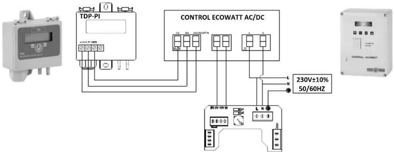
Fig. B
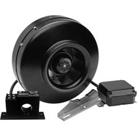
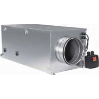
JETLINE 100 ECOWATT
ESPANOL
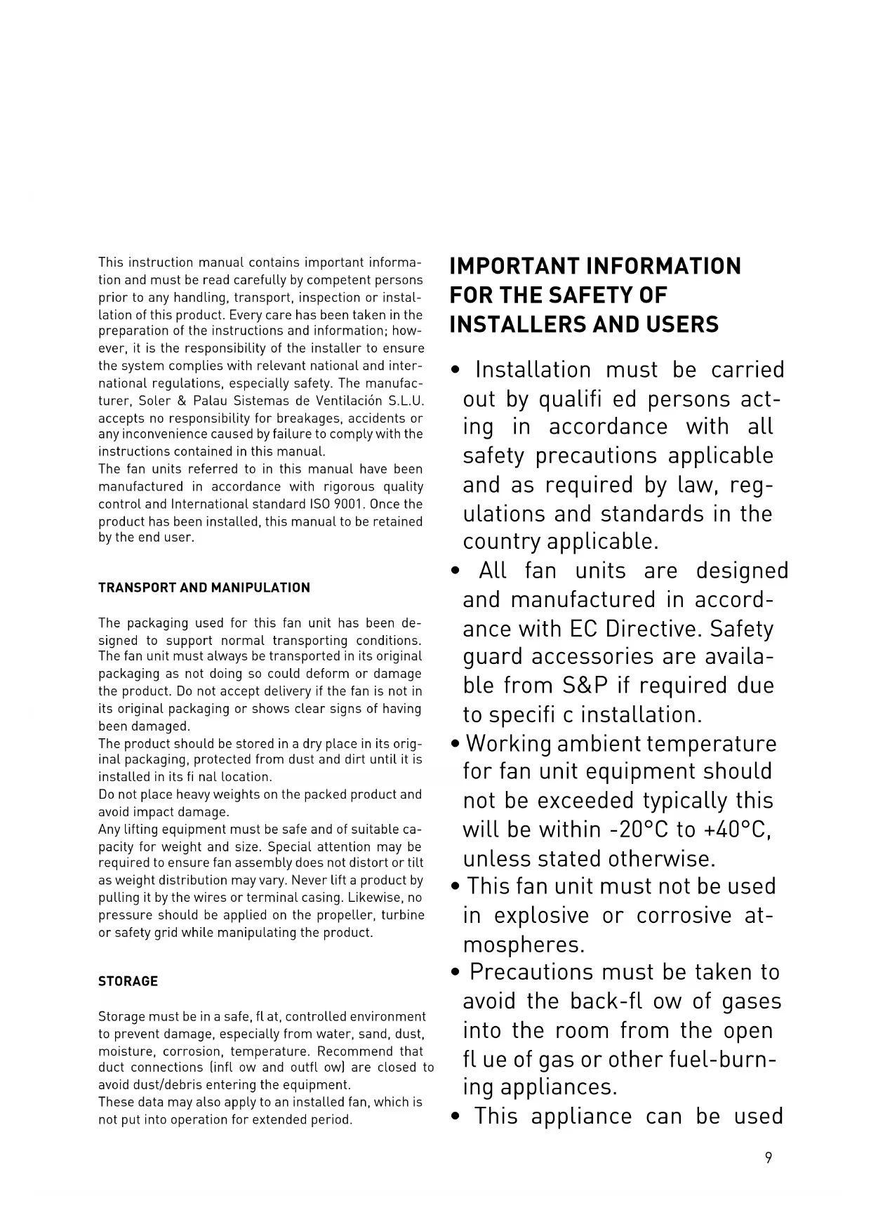
This instruction manual contains important information and must be read carefully by competent persons prior to any handling, transport, inspection or installation of this product. Every care has been taken in the preparation of the instructions and information; however, it is the responsibility of the installer to ensure the system complies with relevant national and international regulations, especially safety. The manufacturer, Soler & Palau Sistemas de Ventilacion S.L.U. accepts no responsibility for breakages, accidents or any inconvenience caused by failure to comply with the instructions contained in this manual.
The fan units referred to in this manual have been manufactured in accordance with rigorous quality control and International standard ISO 9001. Once the product has been installed, this manual to be retained by the end user.
TRANSPORT AND MANIPULATION
The packaging used for this fan unit has been designed to support normal transporting conditions. The fan unit must always be transported in its original packaging as not doing so could deform or damage the product. Do not accept delivery if the fan is not in its original packaging or shows clear signs of having been damaged.
The product should be stored in a dry place in its original packaging, protected from dust and dirt until it is installed in its final location.
Do not place heavy weights on the packed product and avoid impact damage.
Any lifting equipment must be safe and of suitable capacity for weight and size. Special attention may be required to ensure fan assembly does not distort or tilt as weight distribution may vary. Never lift a product by pulling it by the wires or terminal casing. Likewise, no pressure should be applied on the propeller, turbine or safety grid while manipulating the product.
STORAGE
Storage must be in a safe, flat, controlled environment to prevent damage, especially from water, sand, dust, moisture, corrosion, temperature. Recommend that duct connections (infl ow and outfl ow) are closed to avoid dust/debris entering the equipment.
These data may also apply to an installed fan, which is not put into operation for extended period.
IMPORTANT INFORMATION FOR THE SAFETY OF INSTALLERS AND USERS
- Installation must be carried out by qualified persons acting in accordance with all safety precautions applicable and as required by law, regulations and standards in the country applicable.
- All fan units are designed and manufactured in accordance with EC Directive. Safety guard accessories are available from S&P if required due to specific installation.
- Working ambient temperature for fan unit equipment should not be exceeded typically this will be within -20ircC to +40ircC , unless stated otherwise.
- This fan unit must not be used in explosive or corrosive atmospheres.
- Precautions must be taken to avoid the back-flow of gases into the room from the open flue of gas or other fuel-burning appliances.
- This appliance can be used
by children aged from 8 years and above and persons with reduced physical, sensory or mental capabilities or lack of experience and knowledge if they have been given supervision or instruction concerning use of the appliance in a safe way and understand the hazards involved. Children shall not play with the appliance. Cleaning and user maintenance shall not be made by children without supervision.
- Means for disconnection must be incorporated in the fixed wiring according with the wiring rules. An external disconnecting device, which will function as the "designated" disconnect device must be provided, and:
1) It shall disconnect the "Line", while disconnection of the "Neutral" is optional;
2) Its OFF-position shall be clearly marked;
3) Not to position the equipment so that it is difficult to operate it; and
4) The protection current device must be at least 10A, 250V, curve Type C.
SAFETY DURING INSTALLATION
Fan unit equipment should be electrically isolated and locked out before any work started.
The Installer, User is responsible for ensuring that the fan unit is installed, operated and serviced by qualified personnel, acting in accordance with all safety precautions applicable and as required by law, regulations and standards in the country applicable.
Safety protective clothing, equipment, hearing protection, and tools may be required.
Before any installation work is started, ensure that fan unit equipment is correct for application. Location for installation is solid, level, fl at and suitable for mounting fan unit assembly.
Fan unit should be located in position, and assembled with any accessory equipment supplied, on relevant mounting, anti-vibration mountings, safety protection guards, on a solid level base to avoid any distortion and misalignment and with correct air direction as shown on nameplate. Fan unit should then be levelled on any anti-vibration mountings. Flexible connectors must be taught to ensure no disruption to air flow, especially on inlet to fan unit.
Make sure there are no loose elements near the fan unit. When the fan unit is mounted in a duct, check that it is clean of any elements and exclusively used for ventilation system.
The electrical installation must include a double pole switch with a contact clearance of at least 3mm correctly sized and in accordance with the electrical standards of the country of installation.
For electrical connections follow the wiring diagram "A" indicated in this manual.
The fan unit classified as Residential Ventilation Unit with control factor 0,65 have to comply with the requirements of the European Directive 2009/125 and must be installed following the local demand control defini nition given in the regulation n°1253/2014 (See fig.B as example).
STARTUP
- Check fan unit equipment name plate data is appropriate to the location electrical supply, especially Voltage, Frequency, Phase, Amps, speed are correct.
- Check earth connections, electrical terminations and terminal box lid, with any seals, if fitted, are correct.
-
In compliance with Machine Directive, if the fan unit is accessible to operators and is a health and safety risk, adequate protection must be fitted, information for safety equipment, including guards, can be found in S&P accessories catalogue.
-
Check all rotating parts have free, unobstructed movement.
- Check there are no foreign bodies inside the fan unit or that can be drawn into, or fall into fan unit.
- Check the structure is complete and has no damage. Check installation and area is safe and energise fan unit and start motor.
- Check that the impeller and airflow direction is correct, and there are no unusual vibrations.
- Check current does not exceed fan equipment nameplate data.
- If any of the electrical safety devices blow, the fan unit must be quickly disconnected from the mains supply. The whole installation should be carefully checked before trying to start up the fan again. After two hours of operation, check that all fi xings are tight and adjust if necessary.
PUTTING OUT OF SERVICE AND RECYCLING
Maintenance/repairs must be carried out by competent and local regulations. Fan unit equipment should be electrically isolated and locked out before any work started.
Fan unit equipment should be regularly cleaned, frequency depending upon service load and application, but no less than every year. Cleaning should include all areas where dust can accumulate in the fan equipment.
Special attention should be made to any unusual sounds, vibration or temperature.
If any problems are detected the fan unit equipment should be stopped immediately and cause inspected. The impeller and blades should be regularly checked for damage that could cause imbalance in the moving parts.
PUTTING OUT OF SERVICE AND RECYCLING
EEC legislation and our consideration of future generations mean that we should always recycle materials where possible; please do not forget to deposit all packaging in the appropriate recycling bins. If your
device is also labeled with this symbol, please take it to the nearest Waste Management Plant at the end of its servicable life.
The fan unit is mainly made of steel, copper, ferrite, aluminium and plastic. These components should be recycling in the following categories:
- Steel and iron
Aluminium
Non-ferrous metals
Plastics
Insulating materials
Cables
Electronic scrap
To clarify any questions regarding S&P products contact your local distributor. For its location and to obtain the EU Declaration of Conformity certifi ed technical data sheet and copy of this instruction manual, see our web site www.solerpalau.com
INFORMATION REQUIREMENTS FOR RVU
a Trade mark
b Identifi er
c SEC average climate (kWh/[m 2.an])
SEC class
SEC cold climate (kWh/(m2.an))
SEC warm climate [kWh / 2 . an]
d Typology
e Type of drive
f Type of HRC
g Thermal efficiency (%)
h Maximum flow rate (m 3 /h
i Electrical power input at maximum flow rate (W)
Sound power level (LWA)
k Reference flow rate (m-3 / s)
Reference pressure difference (Pa)
m SPI [W/m 3/h]
n Control factor
Control typology
o Maximum internal leakage for BVU [%]
Maximum external leakage for BVU and UVU (%)
p Mixing rate for BVU without duct connection (%)
q Position of visual filter warning
description of visual filter warning
r Instructions to install supply grilles
Instructions to install exhaust grilles
s Internet address
Airflow sensitivity to pressure variation
u Indoor/outdoor air tightness (m 3/h )
v Annual electricity consumption - Average climat (kWh/a)
Annual electricity consumption - Warm climat (kWh/a)
Annual electricity consumption - Cold climat (kWh/a)
w Annual heating saved - Average climat (kWh/a)
Annual heating saved - Warm climat (kWh/a)
Annual heating saved - Cold climat (kWh/a)
FRANÇAIS
c SEC average climate (kWh/(m 2.an)]
SEC class
SEC cold climate [kWh / [m2.an]]
SEC warm climate (kWh/(m 2.an)]
d Typology
e Type of drive
f Type of HRC
g Thermal efficiency [%]
h Maximum flow rate (m3 / h)
i Electrical power input at maximum flow rate (W)
j Sound power level (LWA)
k Reference flow rate (m3 / s)
l Reference pressure difference (Pa)
m SPI [W/m 3 /h]
n Control factor
Control typology
o Maximum internal leakage for BVU (%)
Maximum external leakage for BVU and UVU [%]
p Mixing rate for BVU without duct connection (%)
q Position of visual filter warning
description of visual filter warning
r Instructions to install supply grilles
Instructions to install exhaust grilles
s Internet address
Airflow sensitivity to pressure variation
u Indoor/outdoor air tightness (m3 / h)
v Annual electricity consumption - Average climat (kWh/a)
Annual electricity consumption - Warm climat (kWh/a)
Annual electricity consumption - Cold climat (kWh/a)
w Annual heating saved - Average climat (kWh/a)
Annual heating saved -Warm climat (kWh/a)
Annual heating saved - Cold climat (kWh/a)
POLSKI
WYMOGI INFORMACYJNE DLA RVU
a Nazwa dostawcy
b Numer artykutu


- 6
- ESPANOL
- TRANSPORT AND MANIPULATION
- STORAGE
- IMPORTANT INFORMATION FOR THE SAFETY OF INSTALLERS AND USERS
- SAFETY DURING INSTALLATION
- STARTUP
- PUTTING OUT OF SERVICE AND RECYCLING
- Maintenance/repairs must be carried out by competent and local regulations. Fan unit equipment should be electrically isolated and locked out before any work started.
- INFORMATION REQUIREMENTS FOR RVU
- FRANÇAIS
- POLSKI
- WYMOGI INFORMACYJNE DLA RVU
Brand : Soler & Palau
Model : JETLINE ECOWATT
Category : Fan