
RS 240 - Heating ZIBRO - Free user manual and instructions
Find the device manual for free RS 240 ZIBRO in PDF.
| Product type | Mobile liquid fuel heater |
| Brand | Zibro (Toyotomi) |
| Model | RS 240 |
| Direct heat output | 2.4 kW (2400 W) |
| Average nominal output | 2220 W |
| Fuel consumption | 0.213 to 0.250 L/h |
| Tank runtime | 16 to 18.8 hours |
| Removable tank capacity | 4.0 L |
| Dimensions (W × D × H) | 428 × 295 × 453 mm |
| Weight | 7.5 kg |
| Power supply | 4 LR20 batteries (size D, 1.5 V) – electric ignition |
| Fuel | Liquid fuel for mobile heaters (compliant with French decrees of 18/07/2002 and 25/06/2010) |
| Recommended room volume | 40 to 85 m³ (with ventilation) |
| Wick type | Type F |
| Main functions | Electric ignition, flame adjustment, air quality control system (CO₂), automatic safety shut-off |
| Maintenance and cleaning | Cleaning the fuel filter, wick replacement (by a professional), removing batteries at end of season |
| Safety | Automatic shut-off in case of poor ventilation, CO₂ detector, impact protection, hot grille warning |
| Spare parts and repairability | Wick, batteries, hand pump, transport cap; repairs by an approved specialist |
| General information | 4-year warranty, do not use as main heating, indoor use only, max altitude 1500 m |
Frequently Asked Questions - RS 240 ZIBRO
User questions about RS 240 ZIBRO
0 question about this device. Answer the ones you know or ask your own.
Ask a new question about this device
Download the instructions for your Heating in PDF format for free! Find your manual RS 240 - ZIBRO and take your electronic device back in hand. On this page are published all the documents necessary for the use of your device. RS 240 by ZIBRO.
USER MANUAL RS 240 ZIBRO
natural_image
Black industrial gas stove with grid heating unit and control panel (no visible text or symbols)GB OPERATING MANUAL....PAGE 2
Distributed in Europe by:
TOYOTOMI EUROPE SALES B.V.
Huygensweg 10
5466 AN Veghel, The Netherlands
Email: info@toyotomi.eu Website: www.toyotomi.eu
1 Make sure that children are always aware of the presence of a burning heater.
2 DO NOT move the heater when it is burning or still hot. DO NOT refill nor service the heater when it is burning or still hot.
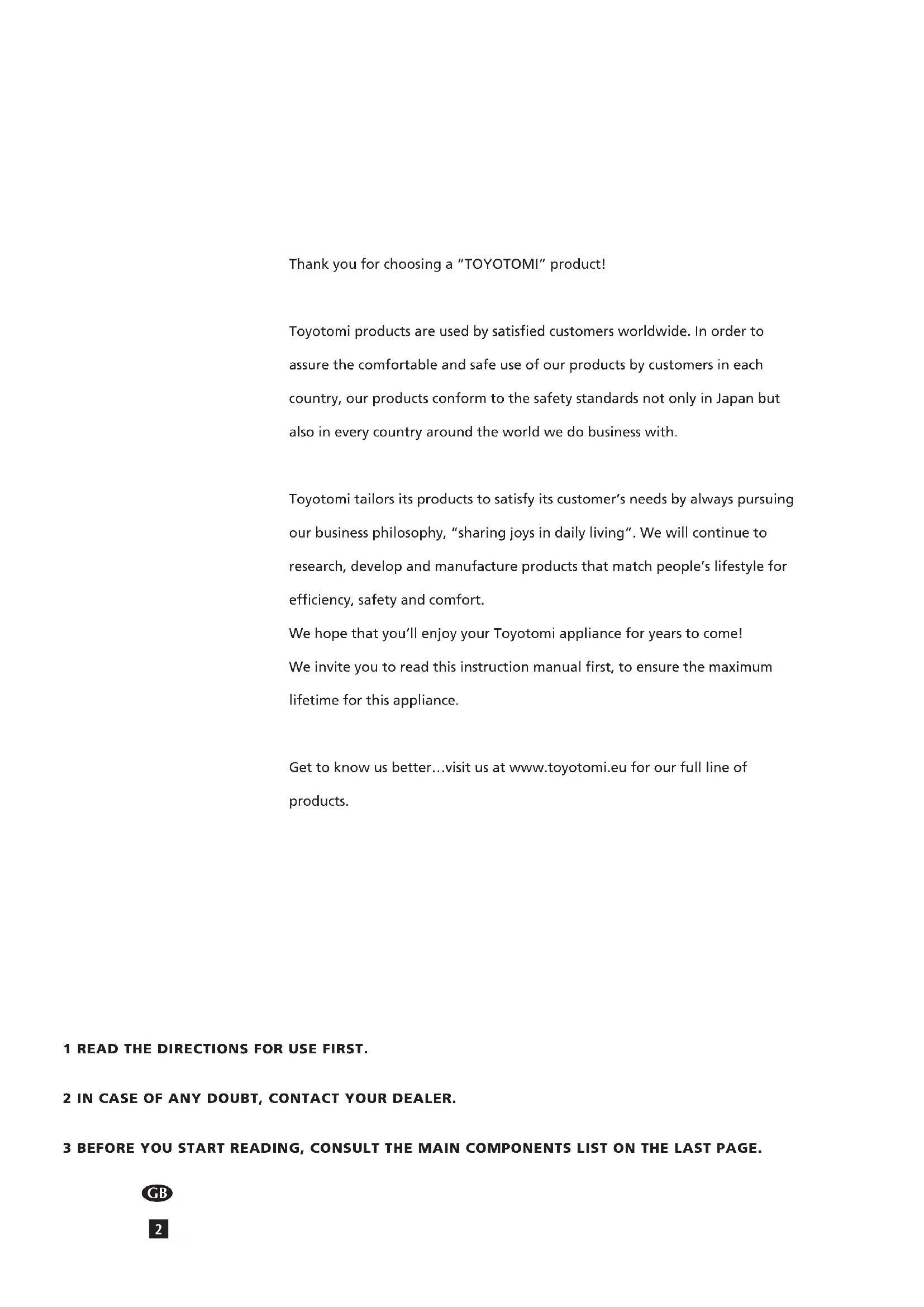
3 Position the front of the heater at a minimum distance of 1.5 metres from walls, curtains, furniture, spray can and gas cylinder. DO NOT store the fuel tank near the heater.
4 DO NOT use the heater in dusty rooms or in very draughty places. In both cases you will not have optimum burning.
5 Switch off the heater, before you go to sleep.
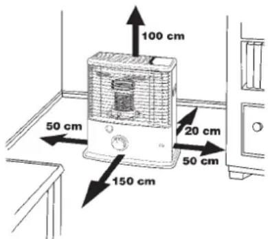
6 Store and move fuel only in suitable tanks and jerrycans.
7 Make sure that the fuel is not exposed to heat or extreme temperature changes. ALWAYS store the fuel in a cool, dry and dark place (sunlight will affect the quality).
8 NEVER use the heater in places where harmful gasses or fumes may be present (e.g. exhaust gasses or paint fumes).
9 The top plate of the heater becomes hot. DO NOT cover the heater (there is a risk of fire). Avoid any contact with the top plate and grille.
10 ALWAYS make sure that there is sufficient ventilation.
11 The heater must not be located immediately below a socket-outlet.
12 Children of less than 3 years should be kept away unless continuously supervised. Children aged from 3 years and less than 8 years shall only switch on/off the appliance provided that it has been placed or installed in its intended normal operating position and they have been given supervision or instruction concerning use of the appliance in a safe way and understand the hazards involved. Children aged from 3 years and less than 8 years shall not plug in, regulate and clean the appliance or perform user maintenance.
CAUTION - Some parts of this product can become very hot and cause burns. Particular attention has to be given where children and vulnerable people are present.
13 Children shall not play with the appliance.
14 Cleaning and user maintenance shall not be made by children without supervision.
15 DO NOT stay near the heater for a long time.
Thank you for choosing a "TOYOTOMI" product!
Toyotomi products are used by satisfied customers worldwide. In order to assure the comfortable and safe use of our products by customers in each country, our products conform to the safety standards not only in Japan but also in every country around the world we do business with.
Toyotomi tailors its products to satisfy its customer's needs by always pursuing our business philosophy, "sharing joys in daily living". We will continue to research, develop and manufacture products that match people's lifestyle for efficiency, safety and comfort.
We hope that you'll enjoy your Toyotomi appliance for years to come! We invite you to read this instruction manual first, to ensure the maximum lifetime for this appliance.
Get to know us better...visit us at www.toyotomi.eu for our full line of products.
1 READ THE DIRECTIONS FOR USE FIRST.
2 IN CASE OF ANY DOUBT, CONTACT YOUR DEALER.
3 BEFORE YOU START READING, CONSULT THE MAIN COMPONENTS LIST ON THE LAST PAGE.
GENERAL DIRECTIONS FOR USE
Below you will find the main steps to be taken for using your heater. For more details, please refer to the MANUAL.
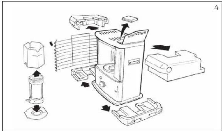
1 Remove all packaging materials (refer to Section A, Fig. A).
2 Fill the removable tank ⑧ and wait 30 minutes before you ignite the heater (refer to Section B, Fig. I).
3 Insert the batteries into the battery holder 10 (refer to Section A, Fig. F).
4 Check whether the combustion chamber ③ is fully upright (refer to Section A, Fig. E).
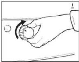
5 Ignite the heater by turning the knurled wick adjustment knob ② as far to the right as possible (refer to Section C, Fig. K).
6 After igniting the heater it will take 30 minutes before you can check if the heater burns well (refer to Section D).
7 Switch off the heater (refer to Section E).
- As a fire precaution, the tank must be filled either when the heater has been switched off or in another room than the room where the heater is installed.
- Always ensure that the tank is closed properly after filling it at a safe distance from all sources of heat and open flames (see Section B).
- The first time you ignite your heater it will smell like 'new' for a short time.
- Store all fuel containers with their original caps and seals in a cool and dark place.
- Fuel ages. Use new fuel at the start of every heating season.
- Only use high quality and water-free pure paraffin in accordance with local legislation (TOYOTOMI fuel).
- Before changing brands and/or types of fuel make sure that the mobile heater first completely empties all of the remaining fuel inside the heater.
WHAT YOU NEED TO KNOW IN ADVANCE
ALWAYS MAKE SURE THAT THERE IS SUFFICIENT VENTILATION
Read this user manual carefully before using the appliance and keep it for future reference. Install this device only when it complies with local/national legislation, ordinances and standards. This product is intended to be used as a heater in residential houses and is only suitable for use in dry locations, in normal household conditions, indoors in living room, kitchen and garage.
This heater is equipped with an air quality control system ⑪. When there is insufficient ventilation in the room or when the heater is being used in a room which is too small, the heater will shut off automatically.
For comfortable and safe heating ensure that there is sufficient ventilation.
NOTE: To avoid unexpected shut off, we recommend to put a door or window ajar when the heater is operating.
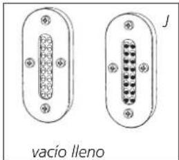
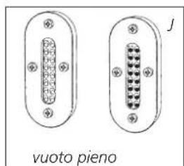
Regardless of the model, you must always make sure that the heater is used in a room large enough to enable the heater to be used safely without extra ventilation (refer to Section J). If the room is smaller than required, you must always open a door or window slightly (ensuring an opening of approx. 2.5 cm). It is important that every room where the heater is used has sufficient air intake and efficient air outflow (both openings must have a minimum cross section of 50 cm ^4 ).
We also recommend doing this in highly insulated or draught-free rooms and/or at altitudes above 1500 metres. Do not use your heater in cellars or other underground areas.
No modifications to the safety system are allowed, as that will invalidate the guarantee that the air probe will work properly. Consult your dealer in case of doubt.
Be aware that the grid and the top plate become hot. If the appliance is covered there is a risk of fire. Due to high surface temperature, keep away from children.
ESPECIALLY FOR FRANCE: Your heater was designed to operate exclusively on fuel for liquid fuel-operated mobile heaters in accordance with the Decrees of 18-07-2002 and 25-06-2010. The use of other fuels is forbidden. Ask your dealer or check our website for the addresses of our retailers. The liquid fuel-operated mobile heater is intended as an extra heater, and not as a continuous source of heat.
ESPECIALLY FOR UNITED KINGDOM: Only use Class C1 paraffin fuel in accordance with BS2869; Part 2, or equivalent.
The user must comply with the following instructions for proper use:
DO NOT
- use petrol.
- use the liquid fuel-operated mobile heater in caravans, boats, and vehicle cabins.
- use the liquid fuel-operated mobile heater in insufficiently ventilated rooms (consult the table of properties for the minimum dimensions of the room to be heated), underground rooms and / or at a height of over 1500 metres.
- modify the heater safety features.
The use of this type of heating in public rooms is subject to prior regulatory permission. Obtain proper information on this in advance.
THE RIGHT FUEL
Your heater has been designed for use with high-quality water-free pure paraffin oil (TOYOTOMI fuel). Only fuels of this kind will ensure clean and proper burning. Lower quality fuel may result in:
- increased possibility of malfunctioning
• incomplete burning
- reduced heater lifetime
- smoke and/or smells
- deposits on the grid or mantle
Using the right fuel is therefore essential for safe, efficient, and comfortable use of your heater.
Damage and/or malfunctions of the heater due to the use of other than high quality water-free pure paraffin oil is not covered by the warranty.
Always refer to (www.toyotomi.eu) for the right fuel for your heater.
Only the use of the correct fuel will ensure safe, efficient, and comfortable use of your heater.

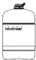
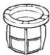
This transportation cap is packed separately in the box. Only this cap ensures trouble-free transportation of the heater after use. Store it well!
natural_image
Exploded view diagram of a blender with internal components and directional arrows indicating assembly (no text or labels)MANUAL
A INSTALLING THE HEATER
1 Carefully remove your heater from the box and check the contents.
In addition to the heater you also need to have:
- a manual fuel pump
- a transportation cap
• these directions for use
Keep the box and the packaging materials (Fig. A) for storage and/or transportation.
2 Remove the other packaging materials:
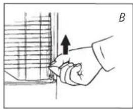
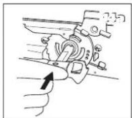
- Remove the packaging material from the grill ⑥. Lift the grill from the slot (Fig. B) and pull it forward.
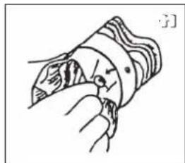
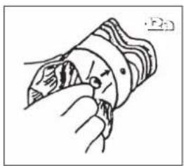
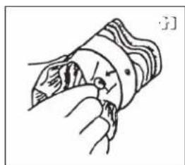
- Pull both ends of the packaging to the rear and at the same time slightly downwards (see Fig. C).
- Remove the combustion chamber ③ from the heater and remove the packaging (see Fig. D).
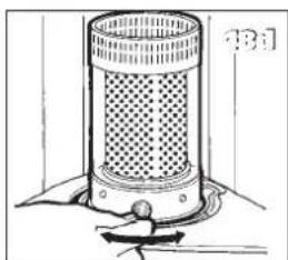
- Put the combustion chamber back into its place. The combustion chamber is positioned correctly when it can be smoothly moved a little to the left and to the right by its handle ④ (Fig. E). Close the grill: Slightly lift it to reposition it in its slot.
- Open the lid of the removable tank ⑦ and remove the piece of cardboard.
3 Fill the removable tank as indicated in Section B.
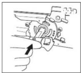
4 By removing the screw to remove the cover and insert the batteries into their holder 10 at the back of the heater (Fig. F).
Ensure that the positive and negative poles match the + and - marks indicated on the battery housing. It is best to use new alkaline batteries (4x D-size).
5 The floor should be firm and completely level. Reposition the heater, when it is not level. Do not correct the situation by placing books or other goods under the heater.
6 Your heater is now ready for use.

Do not use the heater at a height of over 1500 meters.
natural_image
Hand holding a tool interacting with a surface, showing an upward arrow (no text or symbols present)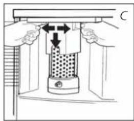
natural_image
Diagram of a mechanical press or clamping device with hands operating it, showing internal components and directional arrows (no text or symbols)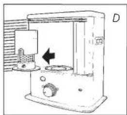
natural_image
Line drawing of a kitchen appliance with a side panel and control knob (no text or symbols)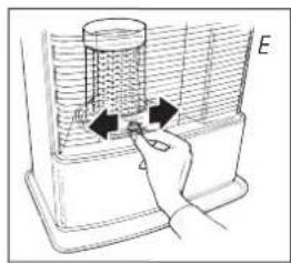
natural_image
Hand holding a device with arrows indicating rotation or movement (no text or symbols)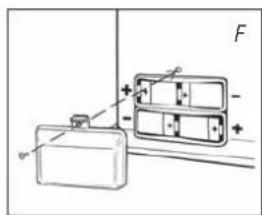
B FILLING FUEL
Fill the removable tank in a suitable place since there can always be some spillage. Follow the procedure below:
1 Make sure that the heater is switched off.
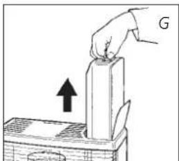
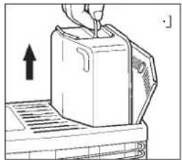
2 Open the upper lid ⑦ and lift the removable tank ⑧ out of the heater (Fig. G). Put down the removable tank (cap pointing upwards, handle on the floor) and screw off the fuel cap (Fig. H).
NOTE: Some drops may leak from the tank.
3 Take the manual fuel pump and insert the smooth, most rigid tube into the jerrycan. Make sure that it is in a higher position than the removable tank (Fig. I). Insert the ribbed hose into the opening of the removable tank.
4 Lock the valve on top of the pump (turn clockwise).
5 Squeeze the pump a few times, until fuel starts flowing into the removable tank. As soon as this happens, there is no need to press any longer.
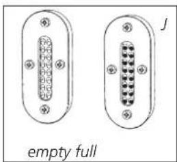
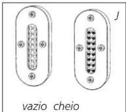
6 Check the fuel guage of removable tank ⑨ while filling the tank (Fig. J). Stop filling by loosening the valve on top of the pump (turn anti-clock-wise), once the gauge indicates that the tank is full. Never overfill the tank, especially not when the fuel is very cold (fuel expands when it heats up).
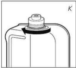
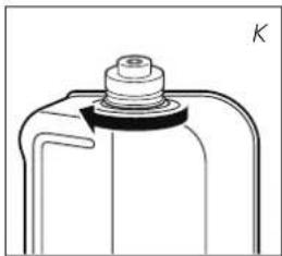
7 Let the remaining fuel in the pump flow back into the jerrycan and carefully remove the pump. Carefully screw the fuel cap back on the tank (Fig. K). Clean off any spilled fuel.
8 Check whether the fuel cap is straight and tightened properly. Reinstall the removable tank in the heater (cap down). Close the lid.
NOTE: Be sure to tighten the fuel tank cap and confirm that there is no leakage of the fuel when the cap side is placed down. Then insert the removable fuel tank into the heater.
C IGNITING THE HEATER
A new heater may give off some smells for a short while, when it is used for the first time. You should therefore provide extra ventilation or ignite the heater outside the living room.

When you use the heater for the first time, first put the filled removable tank into place, and then wait approximately 30 minutes before you ignite the heater. This allows the glass fibre wick to soak up the fuel. Follow the same procedure when you have completely burnt up all fuel from the tank, and after the glass fibre wick has been replaced.
Before igniting the heater, always check the fuel indicator ⑤ to see whether the removable tank needs filling up (Green=full, Red=empty).

Always ignite the heater with the knurled wick adjustment knob ②. Never use matches or a cigarette lighter.
natural_image
Hand pressing a block with an arrow indicating upward motion (no text or symbols)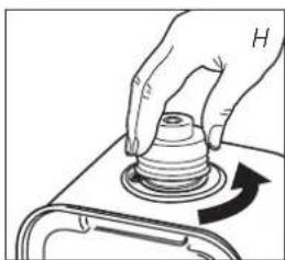
natural_image
Hand pressing a button on a mechanical component with an arrow indicating rotation (no text or symbols)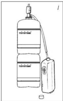
natural_image
Two identical electrical connector pinout diagrams with no text or symbols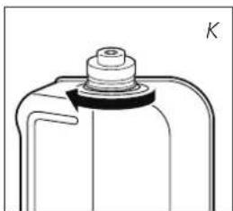
natural_image
Technical line drawing of a mechanical component with a bolt and cap (no text or symbols)
Follow the procedure below:
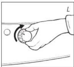
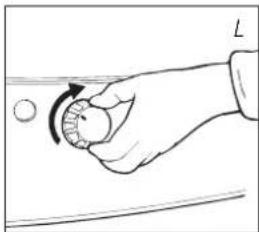
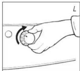
1 Turn the knurled wick adjustment knob ② clockwise to its stop (Fig. L). If you apply more pressure you may turn it slightly further; however, it will automatically return to the start position. When you have set the wick to its highest position, this action will automatically activate the safety device.
When you have ignited the heater and it shuts off again shortly after, the batteries need to be replaced. It is best to use new alkaline batteries (4x D-size).
If the heater has been used only a few times and the wick adjustment knob is not locked, first turn the wick adjustment knob (Fig. M) completely left, before putting the wick in the highest position for ignition (Section C).
After having ignited the heater, always check whether the combustion chamber ③ is level, by sliding it slightly to the left and the right by combustion chamber handle ④ (Fig. E). This should be a smooth movement. If the combustion chamber is not level, this will cause smoke and soot to develop.
D BURNING OF THE HEATER
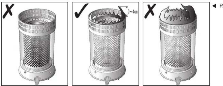
After you have ignited the heater, it will take 30 minutes before you can check whether the heater is burning well. Too high a flame may cause smoke and soot, whereas too low a flame causes smells (Fig. R). Adjust by the knurled wick adjustment knob ② until becoming an appropriate flame (Fig. S).
Burning that is too low may be caused by:
● insufficient fuel (fill the tank)
● poor fuel quality (contact your dealer)
● insufficient ventilation (put window or door ajar)
● wastage of the wick (contact your dealer or replace the wick, refer to section L)
When there is insufficient ventilation in the room, the heater shuts off automatically. After improving the ventilation of the room (e.g. by opening a door or window a little more), the heater can be ignited again.

This heater is equipped with a safety mechanism which switches off the heater when the removable fuel tank is taken out of its compartment (Fig. G). To re-ignite the heater, place the removable fuel tank back in the heater and follow the instructions as described in Section C.
natural_image
Hand holding a circular object with an arrow indicating rotation, no text or symbols present
natural_image
Hand holding a circular object with a curved arrow indicating rotation (no text or symbols)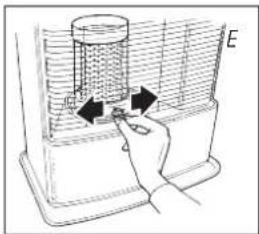
natural_image
Hand inserting a component into a container with arrows indicating direction (no text or symbols)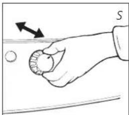
natural_image
Hand holding a small object with an arrow indicating direction, no text or symbols presentE SWITCHING OFF THE HEATER
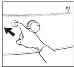
Push the OFF-button ①. The flame will extinguish after a little while (Fig. N).
F MALFUNCTION, CAUSES AND SOLUTIONS
If any malfunctioning cannot be solved from the directions below, please contact your dealer.
THE HEATER DOES NOT IGNITE
- The batteries are not positioned correctly in the holder. Check (Fig. F).
- There is not enough power left in the batteries for the ignition. Replace (Fig. F).
- You have run out of fuel from the tank or the wick has been replaced. After having refilled and replaced the removable tank, wait for 30 minutes before igniting the heater.
IRREGULAR FLAME AND/OR SOOT AND/OR SMELLS
- The combustion chamber ③ has not been positioned correctly. Use the combustion chamber handle ④ to put it level, until you can easily slide it slightly to the left and to the right and the chamber is level.
- You are using fuel which is past its 'use by' date. Start every heating season with fresh fuel.
- You are using the incorrect type of fuel. Refer to THE RIGHT FUEL (See Section 'What you need to know in advance').
- Dust has gathered in the lower part of the heater. Contact your dealer.
- The wick height is not correct. Contact your dealer.
THE HEATER SLOWLY EXTINGUISHES
- The removable tank is empty. See Section B.
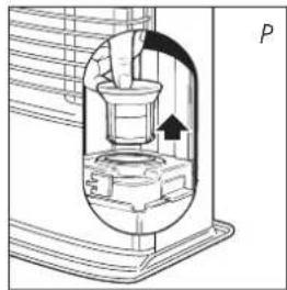
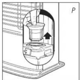
- The fuel filter is contaminated by water. Dry the fuel filter (Section G, Fig. P).
- The lower reservoir is contaminated by water. Contact your dealer.
- The wick has hardened on the upper side. Burn the heater until all fuel is used (Section G). Use the right fuel.
- You are using fuel which is past its 'use by' date. Start every heating season with fresh fuel.
THE HEATER REMAINS BURNING LOW
- Wick position too low. Contact your dealer.
- Before you refilled the tank, the heater had burnt up almost all the fuel. After having refilled and replaced the removable tank, wait for 30 minutes before igniting the heater.
- You are using the incorrect type of fuel. Refer to THE RIGHT FUEL (See Section 'What you need to know in advance').
- The room is insufficiently ventilated. Leave a window or a door wide open for a while.
THE HEATER IS BURNING TOO HIGH
- The flame at the initial stage is tending to make higher flame due to the brand new components. The flame will be lower after approximately 10 hours combustion.
- You are using an incorrect, too volatile type of fuel. Refer to THE RIGHT FUEL (See Section 'What you need to know in advance').
- Wick position too high. Contact your dealer.
natural_image
Hand holding a circular object with an arrow pointing to it, against a horizontal line (no text or symbols)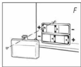
G MAINTENANCE
Your heater needs hardly any maintenance. It is, however, important that you remove dust and stains in time with a damp cloth, because otherwise these may cause stains that are hard to remove. Under normal conditions, only 4 components are subject to wear:
1. THE BATTERIES
You may replace the batteries yourself. Check the spark discharge sound. If the sound is cracked, the voltage of the battery is low. Please change the battery. Check the ignition plug following the maintenance procedure 3 if the sound does not change even after the replacement of the battery. Do not dispose of old batteries along with the other domestic waste. Follow the locally applicable regulations regarding the disposal of domestic chemical waste.
2. THE WICK
To extend the glass fibre wick life, you must occasionally let the heater burn until the tank is completely emptied and the heater extinguishes by itself. Do this when you notice that the flame is weakening. The burn-out will cause some smells, so it is recommended that you take the heater outside of the living room.
3. ELECTRODES
When the electrodes gets dirty by carbon or tar, clean the electrodes. If the electrodes digs into the wick, it may cause the ignition failure. Then fix the position of the electrodes. Be sure not to spill the water on the electrodes.
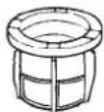
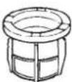
4. THE FUEL FILTER
Check the fuel filter regularly as well.
Remove the removable tank ⑧ from the heater and take out the fuel filter (Fig. P). Some drops of fuel may spill from the filter; keep a cloth at hand. Turn the fuel filter upside down and clean it from all dirt deposits by tapping it on a hard surface. (Never clean it with water!) Reposition the fuel filter in the heater.

Do not remove any heater components yourself. Always contact your dealer for repairs.

Let the heater cool down first, before you start any maintenance or service work.

For maintenance, wear gloves for your safety.
H STORAGE (END OF THE HEATING SEASON)
We recommend that you burn up all the fuel in the fuel tank at the end of the heating season and store the heater properly. Follow the procedure on the next page:
1 Ignite the heater outside the living room and let it burn until all fuel is used.
2 Let the heater cool down.
3 Clean the heater with a damp cloth and then dry it with a dry cloth.
4 Remove the batteries from the holder 10 and store them in a dry place.
5 Clean the fuel filter (refer to section G).
6 Store the heater in a dust-free place, if possible in its original packaging. Unused fuel cannot be used for the next heating season. If there is still some fuel left, do not throw it away, but dispose of it in accordance with the local regulations for the disposal of domestic chemical waste. Always start the new heating season with fresh fuel. When you start re-using the heater, follow the instructions again (starting from Section A and as specified).
fuel filter

natural_image
Technical line drawing of a mechanical device with a valve and housing (no text or symbols)
TRANSPORTATION
Take the following measures to avoid fuel leakage during the transportation of the heater:
1 Let the heater cool down.
2 Remove the removable tank 8 from the heater and remove the fuel filter (Fig. P). Some drops may leak from the filter; keep a cloth at hand. Store the fuel filter and the removable tank outside the heater.
3 Place the transportation cap into the position of the fuel filter (Fig. Q). Press it tight.
4 Always move the heater in an upright position.
J SPECIFICATIONS
| Ignition electrical Dimensions (mm) width 428 | |||
| Fuel paraffin (including base plate) depth 295 | |||
| Capacity (kW) 2.04-2.40 height 453 | |||
| Suitable space (m3)** 40-85 Accessories: transportation cap | |||
| manual fuel pump | |||
| Fuel consumption (l/hr) 0.213-0.250 Required batteries | 4x LR20, MIN 1300 | ||
| Fuel consumption (g/hr) 170-200 | 1.5V, size D | ||
| Burning time per tank (hr) 16-18.8 Wick type F | |||
| Capacity removable tank (litres) 4.0 Weight (kg) | 7.5 | ||
Monitoring of the quality of ventilation (air renewal): Direct measurement of the CO₂ level (NDIR CO₂ sensor 11).
** Specified values are indicative
fuel filter
natural_image
Technical diagram of a mechanical device with a valve and housing, showing no text or symbols.
natural_image
Diagram of a hand pouring liquid into a container with an arrow indicating flow (no text or symbols)
Transportation cap
K WARRANTY PROVISIONS
Your heater comes with a 48 months warranty starting on the date of purchase. Within this period all defects in material or workmanship will be repaired without any charge. The following provisions shall apply regarding this warranty:
1 We expressly dismiss all other claims for damages, including consequential damages.
2 Any repairs or replacements of components within the term of warranty will not result in an extension of the term of warranty.
3 The warranty will no longer apply, when the heater has been modified, non-original parts have been used, or when it is repaired by third parties.
4 The warranty will not apply to parts that are subject to normal wear, such as the batteries, the ignition coil, the wick and the manual fuel pump.
5 The warranty will only apply, when you present the original, dated proof of purchase, provided no changes have been made to it.
6 The warranty will not apply to damages caused by actions not in compliance with the Directions for Use, neglect, and the use of an incorrect type of fuel, or fuel past its use-by date. The use of incorrect fuel can even be dangerous*.
7 Transportation costs and the risks involved during the transportation of the heater or heater components will always be the responsibility of the purchaser.
In order to avoid unnecessary costs, we recommend that you always read the 'Directions for Use' carefully first. In case they offer no solution, please take the heater to your dealer for repair.
REPLACEMENT OF THE WICK
L ENSURE THAT THE HEATER IS OFF AND COMPLETELY COOL BEFORE STARTING TO REPLACE THE WICK.
1 Open the lid and remove the removable tank.
2 Remove the batteries from the battery holder 10.
3 Open the front grill. Remove the combustion chamber from the heater. Close the grill.
4 Pull the knurled wick adjustment knob off the heater.
5 Unscrew the three cabinet screws on the back and sides of the heater. Pull the cabinet forward slightly, and then remove it from the base plate.
6 Unscrew the four wing nuts from the wick holder.
7 Lift the wick holder chassis up until the wick is visible. Place the burner bed next to the heater. (Ensure that the wiring does not become disconnected).
8 Remove the screw on the stem holding the bracket and remove the bracket.
9 Turn right the stem to the end.
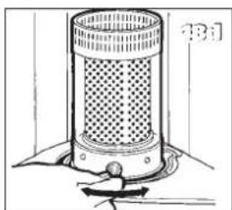
10 Turn the wick sleeve counterclockwise and lift the wick sleeve up. Remove it from the primary air tube.
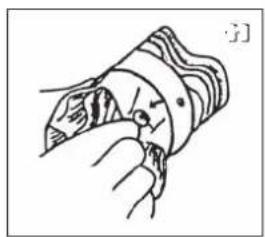
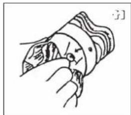
11 Squeeze the wick to loosen the three wick pins and remove the wick from the wick sleeve. Ensure that you are wearing gloves and that you have a container in which to put the old wick.
natural_image
Illustration of a hand using a tool to press or install a container on a tray (no text or symbols visible)
natural_image
Simple line drawing of a device with a container and two rectangular blocks, no text or symbols present.
natural_image
Illustration of a hand inserting a textured object into a cylindrical container (no text or symbols visible)

natural_image
Line drawing of a hand turning a circular component into a pipe (no text or symbols)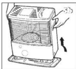
natural_image
Illustration of a portable air conditioner with a hand holding the lid and cooling fan (no text or symbols)
natural_image
Line drawing of a hand turning a valve into a toilet (no text or symbols)
natural_image
Mechanical assembly diagram showing a presser pressing a component with a magnified inset view (no text or symbols)
natural_image
Line drawing of a mechanical assembly with a hand operating a tool (no text or symbols)
natural_image
Diagram of a mechanical device with a hand pressing a button (no text or symbols present)
natural_image
Mechanical assembly diagram showing a rotating component with no visible text or symbols
natural_image
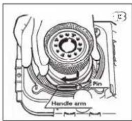
Illustration of a hand holding a curved object with internal bands, no text or symbols present12 Install the wick to the wick sleeve according to the allowed direction engraved on the wick sleeve.
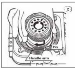
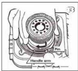
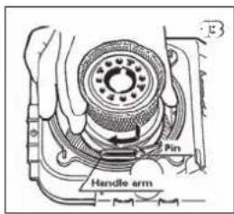
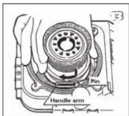
13 Install the wick sleeve (with wick) to the primary air tube. And then turn the wick sleeve clockwise to set in the handle arm.
14 Install the bracket. Then tighten the screw which is holding the stem.
15 Put the wick holder chassis back into position.
16 Screw the four wing nuts hand tight.
17 Place the knurled wick adjustment knob on the wick mechanism. Turn the knob as far to the right as possible. Press the tip-over switch. Check that the wick can be lowered completely. Repeat this check a number of times. If the wick cannot be lowered completely it has not been placed correctly. If this is the case, repeat the procedure from No. 12. Pull the knurled wick adjustment knob off the heater.
18 Put the cabinet back into position and tighten the three screws. Put the knurled wick adjustment knob back into position. Now put the combustion chamber back into position. Check that it is level by sliding it slightly to the left and the right by its handle. Close the grill.
19 Put the filled removable tank into position. Put the batteries into the battery holder (ensure that the positive and negative poles match the + and - marks indicated on the battery housing). Wait 30 minutes after replacing the tank and batteries before using the heater.
natural_image
Hand holding a coiled device with a handle, no visible text or symbols

natural_image
Diagram of a hand operating a mechanical device with a tool, no visible text or symbols
natural_image
Line drawing of a hand using a tool to adjust or install a mechanical component (no text or symbols visible)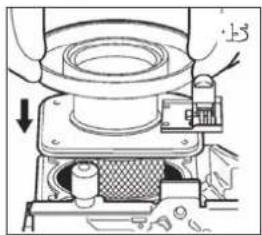
natural_image
Mechanical assembly diagram showing a presser pressing a component with arrows indicating motion (no text or symbols present)
natural_image
Line drawing of a hand pressing down on a small component (no text or symbols)
natural_image
Hand operating a mechanical device with a rotating knob (no text or symbols visible)
natural_image
Mechanical diagram showing a lever mechanism with an arrow indicating motion (no text or symbols present)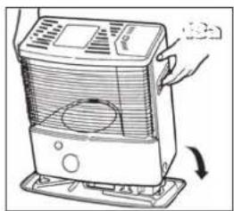
natural_image
Illustration of a portable air purifier with a hand holding the lid and cooling fan (no text or symbols)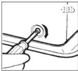
natural_image
Illustration of a hand using a tool to adjust a curved pipe or pipe fitting (no text or symbols visible)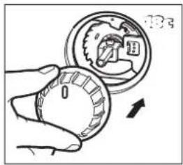

natural_image
Diagram of a cylindrical device with a perforated top and base, connected to a small mechanical component (no text or symbols visible)
natural_image
Line drawing of a hand using a tool to press a container on a tray (no text or symbols)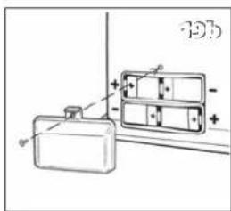
M PRODUCT FICHE
(a) Supplier's name/Trademark TOYOTOMI Europe Sales B.V.
(b) Model RS-240
(c) EEC A
(e) Indirect heat output N/A
(f) EEI 95.0%
(g) Useful energy efficiency 100%
(h) Specific precaution
For assembly, installation or maintenance instructions, please refer to the operating manual.
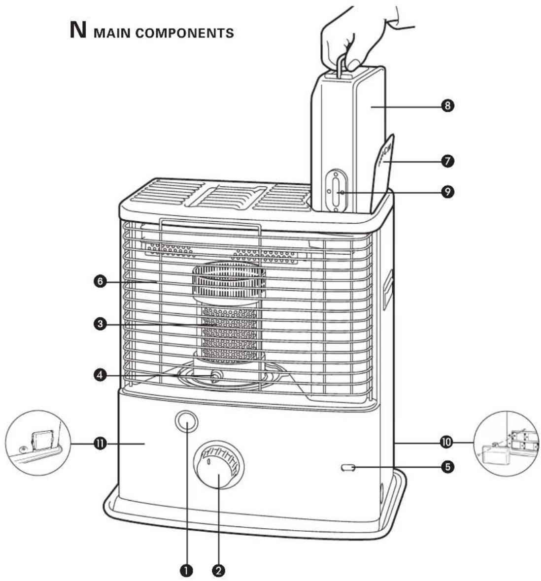
① OFF - button
② Knurled wick adjustment knob
③ Combustion chamber
4 Combustion chamber handle
⑤ Fuel indicator
6 Grill
⑦ Lid for removable tank
8 Removable tank
⑨ Fuel gauge of removable tank
10 Battery holder
⑪ Air quality control system
natural_image
Exploded view diagram of a blender with internal components and directional arrows indicating assembly (no text or labels)GEBRAUCHSANWEISUNG
natural_image
Hand holding a wire fence with an upward arrow, labeled 'B' (no text or symbols on the diagram itself)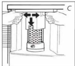
natural_image
Diagram of a mechanical press or clamping device with directional arrows indicating movement (no text or symbols present)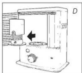
natural_image
Line drawing of a laboratory apparatus with a labeled component (D), showing internal components and a directional arrow (no text or symbols present)natural_image
Hand holding a device with arrows indicating motion or force, no visible text or symbols
natural_image
Hand pressing a block on a mechanical component (no text or symbols visible)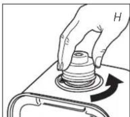
natural_image
Hand pressing a cylindrical component on a base, with an arrow indicating rotation (no text or symbols)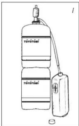
natural_image
3D rendering of a cylindrical industrial filter or reactor with mesh structure and mounting base (no text or symbols visible)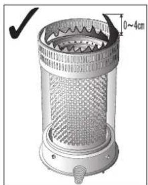
natural_image
Technical illustration of a perforated industrial filter or grating device with a 0–4cm scale indicator (no text or symbols on the device itself)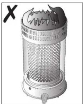
natural_image
Illustration of a portable air purifier with mesh grille and heat exchanger (no text or symbols)◀ R
natural_image
Technical line drawing of a mechanical component with a bolt and flange (no text or symbols)

natural_image
Hand holding a circular knob with a curved arrow indicating rotation (no text or symbols)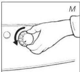
natural_image
Hand holding a circular object with an arrow indicating rotation, no text or symbols present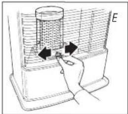
natural_image
Hand placing a component into a container with arrows indicating motion (no text or symbols)
natural_image
Hand holding a small object with an arrow indicating direction, no text or symbols presentnatural_image
Simple line drawing of a hand holding a circular object with an arrow pointing to it, against a horizontal line (no text or symbols)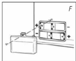
natural_image
Technical line drawing of a mechanical device with a valve and housing (no text or symbols)DE
23
natural_image
Technical diagram of a mechanical device with a valve and housing, showing internal components and an arrow indicating direction (no text or symbols)
natural_image
Diagram of a hand pouring liquid into a container with a downward arrow, no text or symbols present
Transportverschluß
J TECHNISCHE DATEN
natural_image
Illustration of a hand pouring liquid into a container with an upward arrow, placed on a grater (no text or symbols)

natural_image
Illustration of a hand holding a textured container with a plate nearby (no text or symbols)
natural_image
Illustration of a hand holding a circular device with a magnified view showing internal components (no text or symbols)
natural_image
Illustration of a hand using a tool to adjust a car wheel (no text or symbols visible)
natural_image
Illustration of a hand operating a portable electric heater with a cooling fan (no text or symbols visible)
natural_image
Line drawing of a hand turning a button into a car seat (no text or symbols)
natural_image
Mechanical assembly diagram showing a presser pressing a component with a mesh chamber and directional arrow (no text or symbols)
natural_image
Illustration of a hand using a tool to adjust or install a mechanical component (no text or symbols visible)
natural_image
Line drawing of a mechanical device with a hand holding a tool, no text or symbols present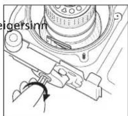


natural_image
Simple line drawing of a hand holding a curved object with internal lines, no text or symbols present.natural_image
Simple line drawing of a hand holding a coiled device (no text or symbols)

natural_image
Diagram of a hand operating a mechanical device with a tool, no visible text or symbols
natural_image
Line drawing of a hand using a tool to press or install a mechanical component (no text or symbols visible)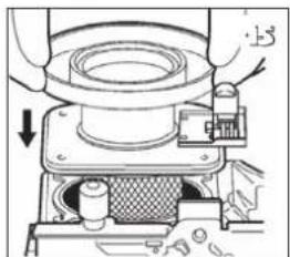
natural_image
Mechanical assembly diagram showing a presser pressing a component with a downward arrow indicating motion (no text or symbols present)
natural_image
Line drawing of a hand pressing down on a small component (no text or symbols)
natural_image
Hand operating a mechanical device with a rotating knob (no text or symbols visible)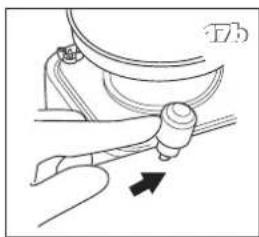
natural_image
Mechanical diagram showing a lever mechanism with an arrow indicating motion (no text or symbols present)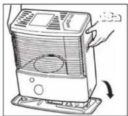
natural_image
Illustration of a portable air purifier with a hand holding the lid and cooling fan (no text or symbols)
natural_image
Close-up of a hand holding a tool with a circular knob, no visible text or symbols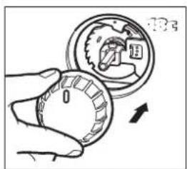

natural_image
Diagram of a cylindrical device with a perforated top and base, connected to a knob (no text or symbols visible)
natural_image
Line drawing of a hand using a tool to press or press a container, with an arrow indicating downward motion (no text or symbols present)

PRODUKTDATENBLATT
LE COMBUSTIBLE APPROPRIÉ
natural_image
Exploded view diagram of a blender with internal components and directional arrows indicating assembly (no text or labels)MANUEL
A INSTALLATION DE L'APPAREIL
natural_image
Hand holding a tool interacting with a grid-like structure, no text or symbols visible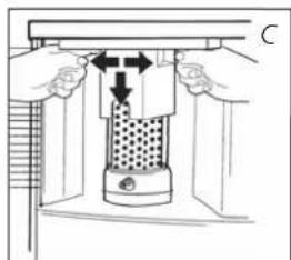
natural_image
Diagram of a mechanical press or clamping device with hands operating it, showing internal components and directional arrows (no text or symbols)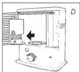
natural_image
Simple line drawing of a water purifier with inlet, outlet, and control panel (no text or symbols)
natural_image
Hand holding a device with arrows indicating a process or operation, no visible text or symbols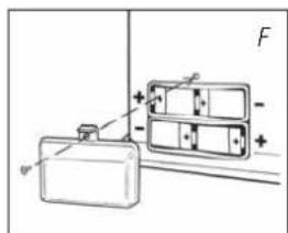
B REMPLISSAGE DU COMBUSTIBLE
natural_image
Diagram of a hand pressing down on a block with an arrow indicating upward motion (no text or symbols)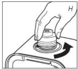
natural_image
Hand pressing a button on a mechanical component with an arrow indicating rotation (no text or symbols)
natural_image
Line drawing of a toy water dispenser with two containers, one connected to a hose and the other holding a battery (no text or symbols)
natural_image
Two identical oval electronic components with pins, labeled 'vide plein' below (no additional text or symbols)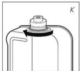
natural_image
Technical line drawing of a mechanical component with a bolt and flange (no text or symbols)CALLUMAGE DE L'APPAREIL
natural_image
Illustration of a cylindrical industrial filter or venturi device with mesh pattern and mounting base (no text or symbols)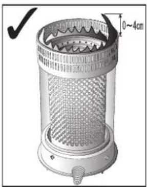
natural_image
Technical illustration of a cylindrical device with mesh structure and measurement annotation (no readable text or symbols)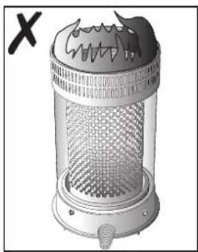
natural_image
Illustration of a cylindrical industrial filter or reactor with mesh structure and a labeled cross mark (no text or symbols on the device itself)◀ R

natural_image
Hand holding a small object with a circular motion arrow, no text or symbols present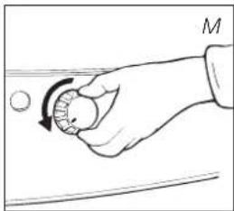
natural_image
Hand holding a circular object with a curved arrow indicating rotation (no text or symbols)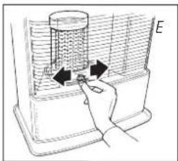
natural_image
Hand inserting a plug into a device with arrows indicating the process (no text or symbols present)
natural_image
Hand holding a small object with an arrow indicating direction, no text or symbols presentFR
natural_image
Hand holding a circular object with an arrow pointing to it, against a horizontal line and curved background (no text or symbols)
FLAMME INSTABLE ET/OU SUIE ET/OU ODEUR.
L'APPAREIL S'ÉTEINT LENTEMENT.
natural_image
Technical line drawing of a mechanical device with a valve and housing (no text or symbols)
natural_image
Technical diagram of a mechanical device with a valve and housing, showing internal components and an arrow indicating direction (no text or symbols)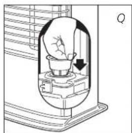
natural_image
Diagram of a light bulb inside a container with an arrow indicating direction (no text or symbols)
Bouchon de transport

CONDITIONS DE GARANTIE
natural_image
Line drawing of a hand using a tool to press or install a container on a tray (no text or symbols)
natural_image
Simple line drawing of a battery and two rectangular compartments with polarity indicators (no text or symbols)
natural_image
Illustration of a hand holding a textured container with a plate nearby (no text or symbols)
natural_image
Illustration of a hand holding a circular object with a magnified inset showing internal components (no text or symbols)
natural_image
Illustration of a hand using a tool to adjust a car wheel (no text or symbols visible)
natural_image
Illustration of a portable electric heater with a hand holding the lid and a paper airplane inside (no text or symbols)
natural_image
Line drawing of a hand turning a button into a toilet (no text or symbols)
natural_image
Mechanical assembly diagram showing a presser pressing a component with a directional arrow (no text or symbols)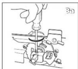
natural_image
Illustration of a hand using a tool to adjust or install a mechanical component (no text or symbols visible)
natural_image
Technical line drawing of a mechanical component with an arrow indicating a force or direction (no text or symbols present)
natural_image
Mechanical assembly diagram showing a rotating component with no visible text or symbols

natural_image
Simple line drawing of a hand holding a curved object with internal lines, no text or symbols present.natural_image
Simple line drawing of a hand holding a coiled device (no text or symbols)


natural_image
Diagram of a hand operating a mechanical device with a tool, no text or symbols present
natural_image
Line drawing of a hand using a tool to adjust or install a mechanical component (no text or symbols visible)
natural_image
Mechanical assembly diagram showing a presser pressing a component with a downward arrow indicating motion (no text or symbols present)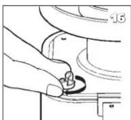
natural_image
Line drawing of a hand pressing down on a small component (no text or symbols)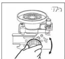
natural_image
Hand operating a mechanical device with a rotating knob (no text or symbols visible)
natural_image
Mechanical diagram showing a lever mechanism with an arrow indicating motion (no text or symbols present)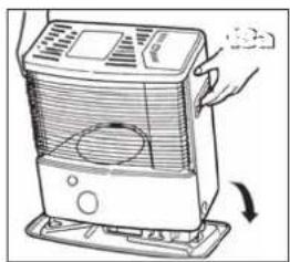
natural_image
Illustration of a hand holding a portable air conditioner unit with a cooling fan and vent, showing airflow direction (no text or symbols)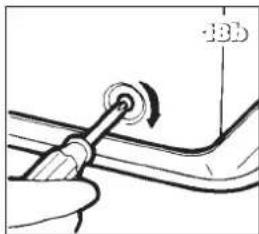
natural_image
Close-up of a hand holding a screwdriver with a circular head and a pointer, no visible text or symbols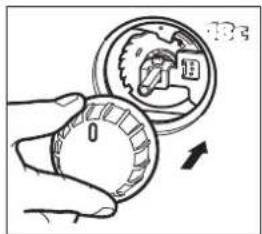

natural_image
Diagram of a cylindrical device with a perforated top and base, showing a small object below (no text or symbols)
natural_image
Line drawing of a hand using a tool to press a container on a tray (no text or symbols)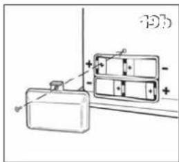

FICHE PRODUIT
WAT U VOORAF MOET WETEN
ALTIJD VOLDOENDE VENTILEREN
natural_image
Exploded view diagram of a blender with internal components and directional arrows indicating assembly (no text or labels)HANDLEIDING
A HET INSTALLEREN VAN DE KACHEL
natural_image
Hand holding a container with liquid and an upward arrow, labeled 'B' (no text or symbols on diagram)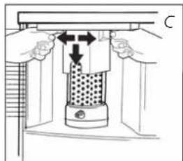
natural_image
Diagram of a mechanical press or clamping device with hands and arrows indicating movement (no text or symbols)
natural_image
Line drawing of a portable kitchen appliance with a side panel and control knob (no text or symbols)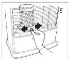
natural_image
Hand holding a container with arrows indicating flow or movement, no visible text or symbolsNL
B VULLEN MET BRANDSTOF
natural_image
Hand pressing a block with an arrow indicating upward motion (no text or symbols)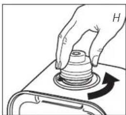
natural_image
Hand pressing a button on a mechanical component with an arrow indicating rotation (no text or symbols)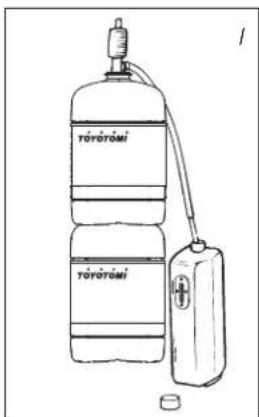
natural_image
3D rendering of a cylindrical industrial fan or filter unit with mesh grille and central hub (no text or symbols visible)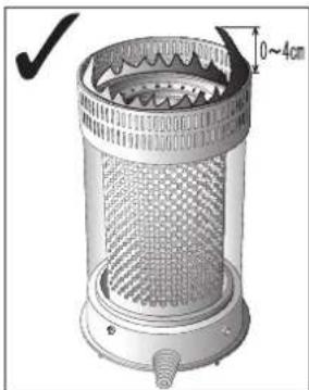
natural_image
Technical illustration of a cylindrical industrial filter or reactor with mesh structure and side profile (no text or symbols)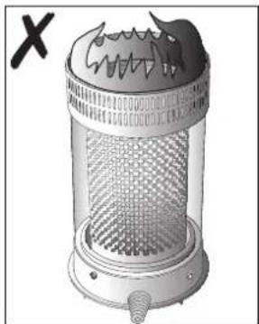
natural_image
Illustration of a portable air purifier with mesh grille and heat exchanger (no text or symbols)◀ R
natural_image
Technical line drawing of a mechanical component with a bolt and flange (no text or symbols)
natural_image
Hand holding a circular object with an arrow indicating rotation (no text or symbols)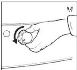
natural_image
Hand holding a circular object with an arrow indicating rotation, no text or symbols present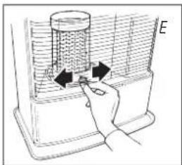
natural_image
Hand inserting a spring into a container with arrows indicating motion (no text or symbols)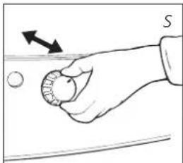
natural_image
Hand holding a small object with an arrow indicating direction, no text or symbols presentnatural_image
Hand holding a circular object with an arrow pointing to it, against a horizontal line background (no text or symbols)
DE KACHEL BLIJFT LAAG BRANDEN.
natural_image
Technical diagram of a mechanical device with a valve and housing, showing internal components and a directional arrow (no text or symbols)
H OPSLAG (EINDE STOOKSEIZOEN)
natural_image
Line drawing of a hand using a tool to press or install a container on a tray (no text or symbols)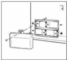
natural_image
Simple line drawing of a battery and two rectangular compartments with polarity indicators (no text or symbols)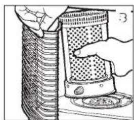
natural_image
Illustration of a hand holding a textured container with a plate, next to a cylindrical structure (no text or symbols)
natural_image
Illustration of a hand holding a circular object with a magnified inset showing internal components (no text or symbols)
natural_image
Line drawing of a hand using a tool to adjust a circular component (no text or symbols present)
natural_image
Illustration of a portable air conditioner with a hand holding the fan (no text or symbols visible)
natural_image
Line drawing of a hand turning a button into a toilet (no text or symbols)
natural_image
Mechanical assembly diagram showing a presser pressing a component with a mesh chamber and directional arrow (no text or symbols)
natural_image
Line drawing of a mechanical assembly with a hand operating a tool (no text or symbols)
natural_image
Technical line drawing of a mechanical component with an arrow indicating a force or direction (no text or symbols present)
natural_image
Mechanical assembly diagram showing a rotating component with no visible text or symbols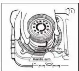

natural_image
Illustration of a hand holding a fish inside a curved container (no text or symbols)natural_image
Simple line drawing of a hand holding a coiled device (no text or symbols)

natural_image
Diagram of a hand operating a mechanical device with a tool, no text or symbols present
natural_image
Line drawing of a hand using a tool to press or install a mechanical component (no text or symbols visible)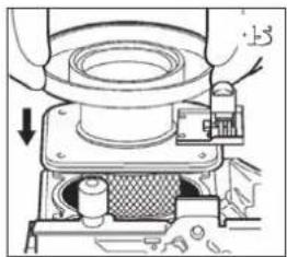
natural_image
Mechanical assembly diagram showing a presser pressing a component with arrows indicating motion (no text or symbols present)
natural_image
Illustration of a hand holding a small object on a mechanical component (no text or symbols visible)
natural_image
Hand operating a mechanical device with a rotating knob (no text or symbols visible)
natural_image
Mechanical diagram showing a lever mechanism with an arrow indicating direction (no text or symbols present)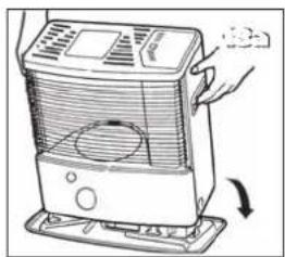
natural_image
Illustration of a hand holding a portable air conditioner unit with a cooling fan and fan blade (no text or symbols)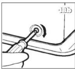
natural_image
Diagram of a hand holding a tool with a circular component, no text or symbols present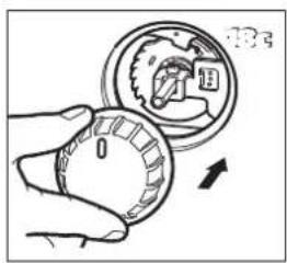

natural_image
Diagram of a cylindrical device with a perforated top and base, connected to a knob (no text or symbols)
natural_image
Line drawing of a hand using a tool to press or install a container, with an arrow indicating downward motion (no text or symbols present)

PRODUCTKAART
MANUAL
A INSTALACION DE LA ESTUFA
natural_image
Hand holding a tool with an upward arrow, pointing to a surface (no text or symbols visible)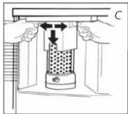
natural_image
Technical diagram of a mechanical press or clamping device with directional arrows indicating movement (no text or symbols present)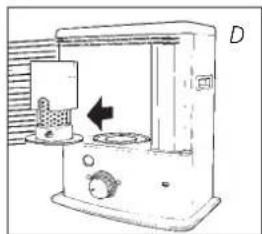
natural_image
Line drawing of a laboratory apparatus with a beaker and control panel, no text or symbols present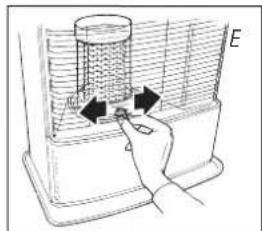
natural_image
Hand holding a device with arrows indicating motion or force, no visible text or symbols
B LLENAR DE COMBUSTIBLE
natural_image
Hand placing a block into a container with an upward arrow, labeled 'G' (no text or symbols on the diagram itself)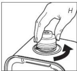
natural_image
Hand pressing a cylindrical component on a tray, with an arrow indicating rotation (no text or symbols)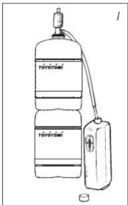
natural_image
Technical line drawing of a mechanical component with a bolt and flange (no text or symbols)natural_image
3D rendering of a cylindrical industrial filter or reactor with mesh structure and central hub (no text or symbols visible)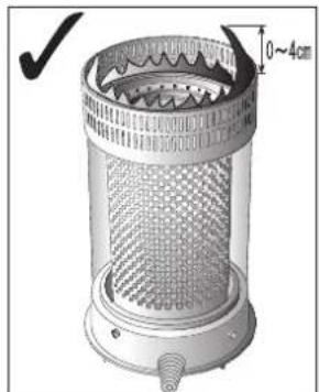
natural_image
Technical illustration of a cylindrical industrial filter or reactor with mesh structure and 0–4cm height annotation (no text or symbols on the diagram itself)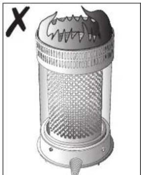
natural_image
Illustration of a portable electric heater with a mesh grille and heat sink (no text or symbols)◀ R
natural_image
Hand holding a circular knob with a rotating arrow, no text or symbols present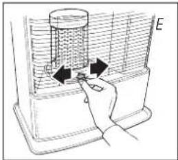
natural_image
Hand inserting a plug into a fan-shaped device (no text or symbols visible)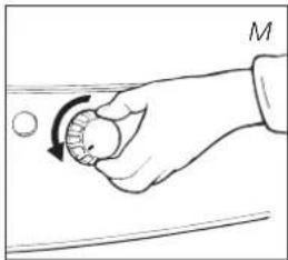
natural_image
Hand holding a circular object with a rotating arrow, no text or symbols present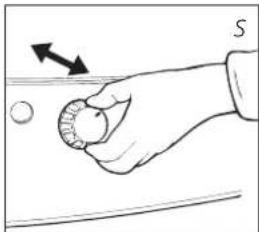
natural_image
Hand holding a circular object with an arrow indicating direction, no text or symbols presentnatural_image
Hand holding a circular object with an arrow pointing to it, against a horizontal line and curved background (no text or symbols)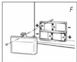
G MANTENIMIENTO
natural_image
Technical line drawing of a mechanical device with a central component and an arrow indicating direction (no text or symbols)
TRANSPORTE
natural_image
Technical diagram of a mechanical device with a valve and housing, showing internal components and an arrow indicating direction (no text or symbols)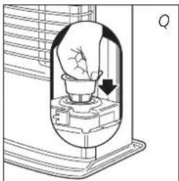
natural_image
Diagram of a hand pouring liquid into a container with an arrow indicating flow direction (no text or symbols)
Tapón de transporte
K CONDICIONES DE GARANTÍA
natural_image
Illustration of a hand using a tool to press a container on a tray (no text or symbols visible)
natural_image
Simple line drawing of a device with a container and two rectangular blocks, no text or symbols present.
natural_image
Illustration of a hand inserting a textured object into a cylindrical container (no text or symbols visible)

natural_image
Line drawing of a hand using a tool to adjust a circular component (no text or symbols present)
natural_image
Illustration of a portable air conditioner with a hand inserting a fan (no text or symbols)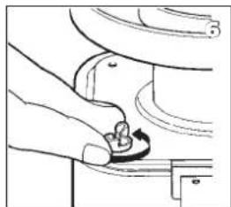
natural_image
Line drawing of a hand holding a knob on a toilet sink (no text or symbols)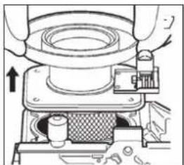
natural_image
Technical line drawing of a mechanical assembly with no visible text or symbols
natural_image
Line drawing of a mechanical assembly with a hand operating a tool (no text or symbols)
natural_image
Diagram of a mechanical device with a hand holding a tool, showing motion lines and no visible text or symbols.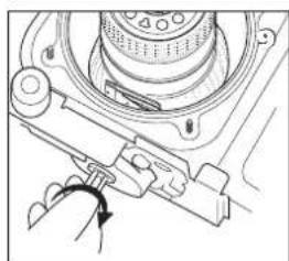
natural_image
Mechanical assembly diagram showing a rotating component with no visible text or symbols

natural_image
Simple line drawing of a fish being cut with a knife, no text or symbols presentnatural_image
Simple line drawing of a hand holding a coiled device (no text or symbols)

natural_image
Diagram of a hand operating a mechanical device with a tool, no text or symbols present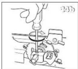
natural_image
Line drawing of a hand using a tool to adjust or install a mechanical component (no text or symbols visible)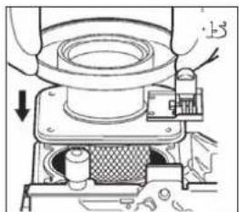
natural_image
Mechanical assembly diagram showing a presser pressing a component with a downward arrow indicating motion (no text or symbols present)
natural_image
Line drawing of a hand holding a small object, possibly a tool or component, with no visible text or symbols.
natural_image
Hand operating a mechanical device with a rotating knob (no text or symbols visible)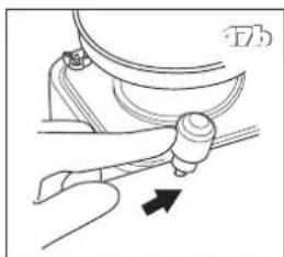
natural_image
Line drawing of a hand holding a tool with an arrow indicating direction (no text or symbols)
natural_image
Illustration of a portable air conditioner unit with a hand holding the lid and cooling fan (no text or symbols visible)
natural_image
Close-up of a hand holding a tool with a circular knob, pointing to a component labeled '13b' (no other text or symbols visible)
natural_image
Diagram of a cylindrical device with a perforated top and base, connected to a knob (no text or symbols visible)
natural_image
Line drawing of a hand using a tool to press or install a container, with an arrow indicating downward motion (no text or symbols present)
M FICHA DE PRODUCTO
MANUALE
natural_image
Hand holding a container with liquid and an upward arrow, labeled 'B' (no text or symbols on diagram)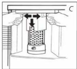
natural_image
Technical diagram of a mechanical press or clamping device with directional arrows indicating movement (no text or symbols present)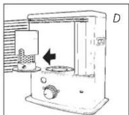
natural_image
Line drawing of a laboratory apparatus with a labeled component (D), no text or symbols present.
natural_image
Diagram of a hand holding a cylindrical object inside a container, with arrows indicating direction (no text or symbols)
B RIFORNIMENTO DEL COMBUSTIBILE
C ACCENSIONE DELLA STUFA
natural_image
Hand pressing a block with an arrow indicating upward motion (no text or symbols)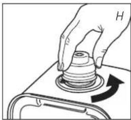
natural_image
Hand pressing a cylindrical component on a base, with an arrow indicating rotation (no text or symbols)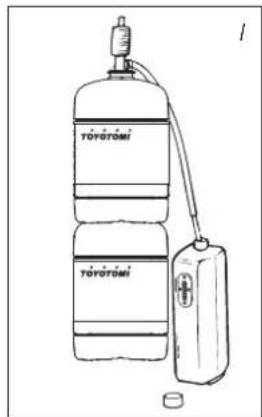
natural_image
Two identical oval electronic components with pins, labeled 'vuoto pieno' at the bottom (no additional text or symbols)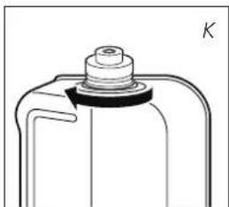
natural_image
Technical line drawing of a mechanical component with a bolt and cap (no text or symbols)
D LA COMBUSTIONE DELLA STUFA
natural_image
Hand holding a circular object with an arrow indicating rotation, no text or symbols present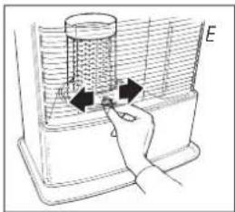
natural_image
Hand inserting a plug into a container with arrows indicating the process (no text or symbols)
natural_image
Hand holding a small object with an arrow indicating direction, no text or symbols presentE SPEGNIMENTO DELLA STUFA
natural_image
Hand holding a circular object with an arrow pointing to it, against a horizontal line and a vertical bar (no text or symbols)
G LA MANUTENZIONE
natural_image
Technical diagram of a mechanical device with a valve and housing, showing internal components (no text or labels)
Il filtro
natural_image
Technical diagram of a mechanical device with a valve and housing, showing internal components (no text or labels)IT
natural_image
Diagram of a hand pouring liquid into a container with an arrow indicating flow (no text or symbols)natural_image
Line drawing of a hand using a tool to press or install a container on a tray (no text or symbols)
natural_image
Simple line drawing of a battery and two rectangular compartments with polarity indicators (no text or symbols)
natural_image
Illustration of a hand holding a textured container with a plate, next to a cylindrical structure (no text or symbols)
natural_image
Illustration of a hand holding a circular object with a magnified inset showing internal components (no text or symbols)
natural_image
Illustration of a hand using a tool to adjust a car wheel (no text or symbols visible)
natural_image
Illustration of a hand operating a portable electric heater with a cooling fan (no text or symbols visible)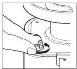
natural_image
Hand holding a knob with a curved arrow indicating rotation (no text or symbols)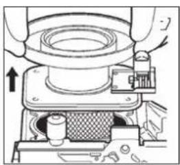
natural_image
Mechanical assembly diagram showing a presser pressing a component with a directional arrow (no text or symbols)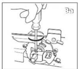
natural_image
Line drawing of a hand using a sewing machine to adjust or install a mechanical component (no text or symbols present)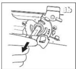
natural_image
Diagram of a mechanical device with a hand holding a tool, showing motion lines and no visible text or symbols.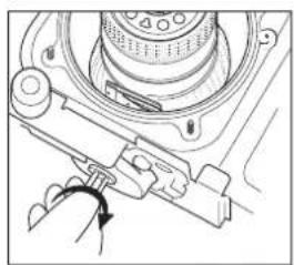
natural_image
Mechanical assembly diagram showing a rotating component with a curved arrow indicating rotation (no text or symbols present)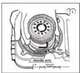
natural_image
Simple line drawing of a hand holding a curved object with internal lines, no text or symbols present.natural_image
Hand holding a coiled device with a handle, no visible text or symbols

natural_image
Diagram of a hand operating a mechanical device with a tool, no visible text or symbols
natural_image
Line drawing of a hand using a tool to adjust or install a mechanical component (no text or symbols visible)

natural_image
Line drawing of a hand pressing down on a small component (no text or symbols)
natural_image
Hand operating a mechanical device with a rotating knob (no text or symbols visible)
natural_image
Mechanical diagram showing a lever mechanism with an arrow indicating motion (no text or symbols present)
natural_image
Illustration of a hand holding a portable air conditioner unit with a cooling fan and fan blade (no text or symbols)
natural_image
Illustration of a hand turning a car wheel with a knob, no text or symbols present

natural_image
Diagram of a cylindrical device with a perforated top and base, connected to a knob (no text or symbols visible)
natural_image
Line drawing of a hand using a tool to press or press a container on a tray (no text or symbols)
M SCHEDA PRODOTTO
(a) Nome / Marchio del fornitore TOYOTOMI Europe Sales B.V.
(b) Modello RS-240
natural_image
Exploded view diagram of a blender with internal components and directional arrows indicating assembly (no text or labels)MANUAL
natural_image
Hand holding a tool interacting with a water barrier (no text or symbols visible)
natural_image
Diagram of a mechanical press or valve assembly with hands and arrows indicating movement (no text or symbols)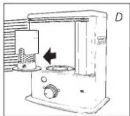
natural_image
Line drawing of a kitchen appliance with a side panel and control knob (no text or symbols)
natural_image
Hand placing a button into a container with arrows indicating motion (no text or symbols)
B ABASTECIMENTO DE COMBUSTÍVEL
natural_image
Hand pressing a block with an arrow indicating upward motion (no text or symbols)
natural_image
Illustration of a hand pressing a cylindrical component on a base, with an arrow indicating rotation (no text or symbols)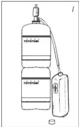
natural_image
Technical line drawing of a mechanical component with a central bolt and flange (no text or symbols)
natural_image
3D rendering of a cylindrical industrial filter or reactor component with mesh structure and mounting base (no text or symbols)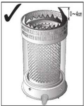
natural_image
Technical illustration of a cylindrical device with mesh pattern and side profile, showing a 0–4cm height dimension (no text or symbols on the device itself)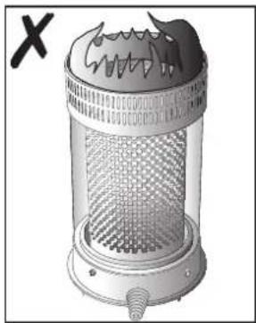
natural_image
Illustration of a cylindrical industrial or gas purifier with mesh structure and heat exchanger (no text or symbols)◀ R
natural_image
Hand holding a circular dial with a curved arrow indicating rotation (no text or symbols)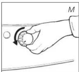
natural_image
Hand holding a circular object with an arrow indicating rotation, no text or symbols present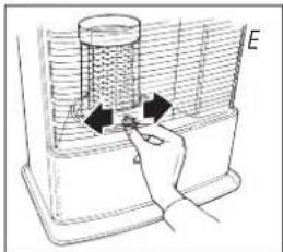
natural_image
Hand inserting a component into a container with arrows indicating direction (no text or symbols)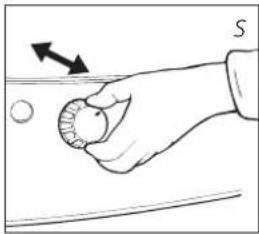
natural_image
Hand holding a circular object with an arrow indicating direction, no text or symbols presentE DESLIGAR O AQUECEDOR
natural_image
Hand holding a compass needle with an arrow indicating direction (no text or symbols)
G MANUTENÇÃO
natural_image
Technical diagram of a mechanical device with a central component and directional arrow (no text or symbols)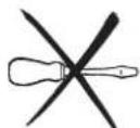
natural_image
Technical line drawing of a mechanical device with a central component and directional arrow (no text or symbols)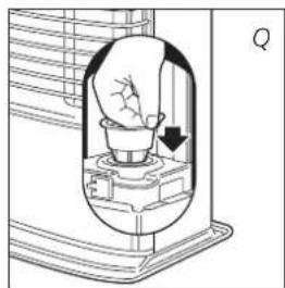
natural_image
Diagram of a light bulb inside a container with an arrow indicating direction (no text or symbols)
Tampa de transporte
K CONDIÇÕES DE GARANTIA
natural_image
Line drawing of a hand using a tool to press or install a container on a tray (no text or symbols)
natural_image
Simple line drawing of a battery and two rectangular compartments with polarity indicators (no text or symbols)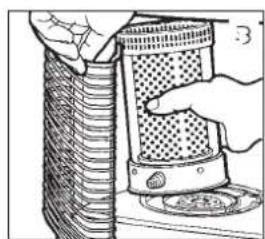
natural_image
Illustration of a hand holding a textured container with a plate nearby (no text or symbols)
natural_image
Illustration of a hand holding a circular object with a magnified inset showing internal components (no text or symbols)
natural_image
Illustration of a hand turning a car wheel with a wrench (no text or symbols)
natural_image
Illustration of a hand holding a portable air conditioner unit with cooling fan and fan cover (no text or symbols)
natural_image
Line drawing of a hand turning a button into a car seat (no text or symbols)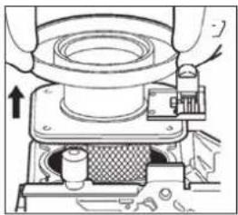
natural_image
Mechanical assembly diagram showing a presser pressing a component with a mesh chamber and tool handle (no text or symbols visible)
natural_image
Line drawing of a mechanical assembly with a hand operating a tool (no text or symbols)
natural_image
Line drawing of a mechanical device with an arrow pointing to a hand (no text or symbols present)
natural_image
Mechanical assembly diagram showing a rotating component with no visible text or symbols

natural_image
Simple line drawing of a hand holding a curved object with internal bands (no text or symbols)natural_image
Simple line drawing of a hand holding a coiled device (no text or symbols)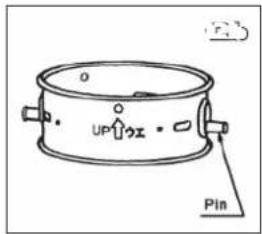


natural_image
Diagram of a hand operating a mechanical device with a tool, no visible text or symbols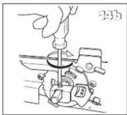
natural_image
Line drawing of a hand using a tool to adjust or install a mechanical component (no text or symbols visible)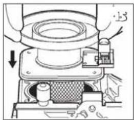
natural_image
Mechanical assembly diagram showing a presser pressing a component with arrows indicating motion (no text or symbols present)
natural_image
Line drawing of a hand holding a small object, possibly a tool or component, with no visible text or symbols.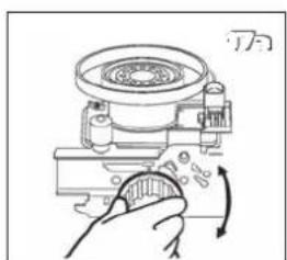
natural_image
Hand operating a mechanical device with a rotating knob (no text or symbols visible)
natural_image
Mechanical diagram showing a lever mechanism with an arrow indicating motion (no text or symbols present)
natural_image
Illustration of a portable air conditioner unit with a hand holding the lid and cooling fan (no text or symbols visible)
natural_image
Illustration of a hand using a tool to adjust a curved pipe or pipe fitting (no text or symbols visible)

natural_image
Diagram of a cylindrical device with a perforated top and base, showing a small object below (no text or symbols)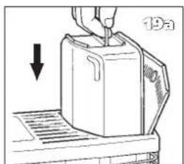
natural_image
Line drawing of a hand using a tool to press a container on a tray (no text or symbols)
M FICHA DE PRODUTO
(a) Nome do fornecedor/ marca comercial TOYOTOMI Europe Sales B.V.
(b) Modelo RS-240
HVAD MAN F∅RST SKAL VIDE
S∅RG ALTID FOR TILSTRÆKKELIG VENTILATION
VEJLEDNING
A INSTALLATION AF OVNEN
natural_image
Hand holding a container with liquid and an upward arrow, labeled 'B' (no text or symbols on diagram)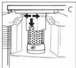
natural_image
Diagram of a mechanical press or valve assembly with hands and arrows indicating movement (no text or symbols)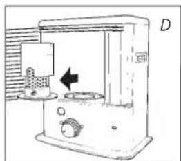
natural_image
Line drawing of a stainless steel kitchen appliance with a side panel and control panel (no text or symbols)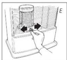
natural_image
Hand holding a device with arrows pointing to a component inside a container (no text or symbols visible)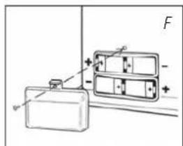
B PÄFYLDNING AF BRÄNDSTOF
natural_image
Hand placing a block into a container with an upward arrow, labeled 'G' (no text or symbols on the diagram itself)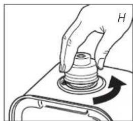
natural_image
Hand pressing a button on a mechanical component with an arrow indicating rotation (no text or symbols)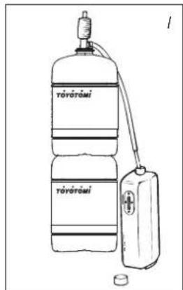
natural_image
Two identical oval-shaped electronic components with pins, labeled 'Tom Fuld' below (no additional text or symbols)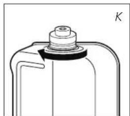
natural_image
Technical line drawing of a mechanical component with a cylindrical top and flange (no text or symbols)
natural_image
Hand holding a knob with a circular dial and an arrow indicating rotation (no text or symbols)En for lav flamme kan skyldes:
natural_image
Hand holding a circular object with an arrow indicating rotation, no text or symbols present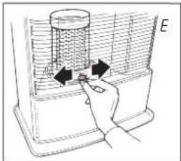
natural_image
Hand inserting a plug into a heat exchanger unit (no text or symbols visible)
natural_image
Hand holding a small circular object with an arrow indicating direction (no text or symbols)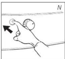
natural_image
Hand holding a circular object with an arrow pointing to it, against a horizontal line (no text or symbols)F FUNKTIONSFEJL, ÅRSAGER OG L∅SNINGER
G OM VEDLIGEHOLDELSEN
natural_image
Diagram of a mechanical device with a valve and housing, showing internal components and an arrow indicating direction (no text or symbols)
TRANSPORT
natural_image
Technical diagram of a mechanical device with a valve and housing, showing internal components and an arrow indicating direction (no text or symbols)
natural_image
Diagram of a light bulb inside a container with an arrow indicating direction (no text or symbols)
Transportprop
K GARANTIBETINGELSERNE
UDSKIFTNING AF VÄGEN
L INDEN DU PÅBEGYNDER UDSKIFTNINGEN AF VÄGEN, SKAL KAMINEN VÄRE SLUKKET OG HELT AFKÖLET.
natural_image
Line drawing of a hand using a tool to press or install a container on a tray (no text or symbols)
natural_image
Simple line drawing of a battery and two rectangular compartments with polarity indicators (no text or symbols)
natural_image
Illustration of a hand holding a textured container over a tray with food items (no text or symbols visible)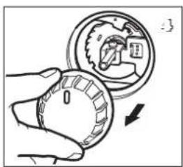
natural_image
Illustration of a hand holding a circular object with a magnified inset showing internal components (no text or symbols)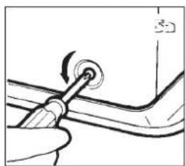
natural_image
Line drawing of a hand using a tool to adjust a car wheel (no text or symbols)
natural_image
Illustration of a hand holding a portable air conditioner unit with a cooling fan and fan blade (no text or symbols)
natural_image
Illustration of a hand turning a button into a mechanical component (no text or symbols)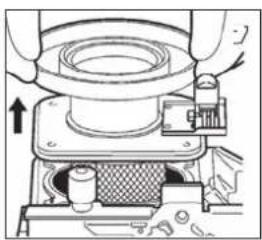
natural_image
Mechanical assembly diagram showing a presser pressing a component with a directional arrow (no text or symbols)
natural_image
Line drawing of a hand using a tool to adjust or install a mechanical component (no text or symbols visible)
natural_image
Mechanical diagram showing a lever mechanism with a hand pressing a workpiece (no text or symbols present)
natural_image
Mechanical assembly diagram showing a rotating component with no visible text or symbols
natural_image
Simple line drawing of a hand holding a curved object with internal bands (no text or symbols)natural_image
Simple line drawing of a hand holding a coiled device (no text or symbols)
natural_image
Diagram of a mechanical device with a hand operating a tool (no text or symbols visible)
natural_image
Line drawing of a hand using a tool to press or install a mechanical component (no text or symbols visible)
natural_image
Mechanical assembly diagram showing a presser pressing a component with a downward arrow indicating motion (no text or symbols present)
natural_image
Line drawing of a hand holding a small object, possibly a tool or component, with no visible text or symbols.
natural_image
Hand operating a mechanical device with a rotary knob (no text or symbols visible)
natural_image
Line drawing of a hand gripping a mechanical component with an arrow indicating direction (no text or symbols)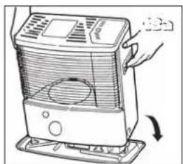
natural_image
Illustration of a hand operating a portable air conditioner unit with a cooling fan (no text or symbols visible)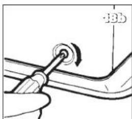

natural_image
Illustration of a cylindrical device with a perforated top and base, connected to a small sphere on a stand (no text or symbols visible)
natural_image
Line drawing of a hand using a tool to press or press a kettle on a tray (no text or symbols)

DATABLAD
HÅNDBOK
A INSTALLERE OVNEN
natural_image
Hand holding a container with liquid and an upward arrow, labeled 'B' (no text or symbols on diagram)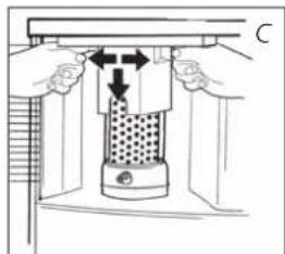
natural_image
Diagram of a mechanical press or clamping device with directional arrows indicating movement (no text or symbols present)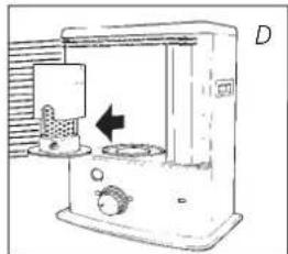
natural_image
Diagram of a laboratory apparatus with a control panel and directional arrow (no text or symbols)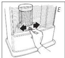
natural_image
Hand placing a button into a fan inside an air conditioner unit (no text or symbols visible)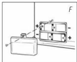
natural_image
Simple line drawing of a hand pressing down on a block with an arrow indicating upward motion (no text or symbols)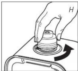
natural_image
Illustration of a hand pressing a cylindrical component on a base, with an arrow indicating rotation (no text or symbols)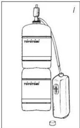
natural_image
Two identical electrical connector pinouts with terminal symbols, labeled 'tom full' and 'J', no additional text or symbols present.
natural_image
Technical line drawing of a mechanical component with a bolt and flange (no text or symbols)
natural_image
Hand holding a circular knob with a curved arrow indicating rotation (no text or symbols)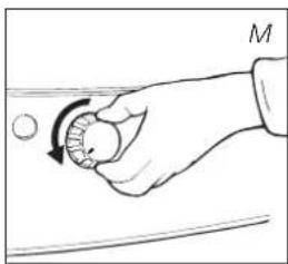
natural_image
Hand holding a circular object with an arrow indicating rotation, no text or symbols present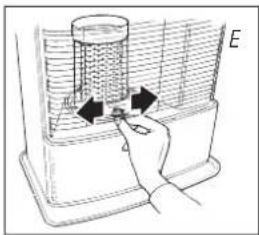
natural_image
Hand inserting a spring into a fan inside an air conditioner unit (no text or symbols visible)
natural_image
Hand holding a circular object with an arrow indicating direction, no text or symbols present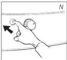
natural_image
Hand holding a knob with an arrow pointing to the knob, against a horizontal line (no text or symbols)
natural_image
Diagram of a mechanical device with a piston and housing, showing internal components and an arrow indicating direction (no text or symbols)
TRANSPORT
Iverksett følgende tiltak for å unngå at det lekker drivstoff när du transporterer ovnen:
1 La varmeovnen avkjøle.
2 Ta ut den uttakbare beholder I ut av ovnen og ta ut drivstofffilteret (fig. P). Noen dråper kan lekke fra filteret; ha en klut tilgjengelig. Oppbevar drivstofffilteret og beholderen utenfor varmeovnen.
3 Sett transportdekslet der drivstofffilteret skal sitte (fig. Q). Trykk det godt på plass.
4 Sett alltid varmeovnen i stående stilling.
J SPESIFIKASJONER
| Tenning elektrisk Mål (mm) bredde 428 | |||
| Drivstoff parafin (også sokkelplaten) dybde 295 | |||
| Kapasitet (kW) 2,04-2,40 | høyde 453 | ||
| Egnet plass ( m^3 )** | 40-85 | Tilbehør | manuell drivstoffpumpe, transportdeksel |
| Drivstofforbruk (l/t) | 0,213-0,250 | Batterieres | 4x LR14 kg, MN 1400 |
| Drivstoff-forbruk (g/t) | 170-200 | 1,5V, Size D | |
| Forbrenningstid per beholder (t) | 16-18,8 | Veketype | F |
| Kapasitet uttakbar beholder (liter) | 4,0 | Vekt (kg) | 7,5 |
natural_image
Technical diagram of a mechanical device with a valve and housing, showing no text or symbols.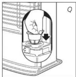
natural_image
Diagram of a light bulb inside a container with an arrow indicating direction (no text or symbols)
Transportdeksel
K GARANTIBETINGELSER
natural_image
Illustration of a hand using a tool to press or install a container on a tray (no text or symbols visible)
natural_image
Simple line drawing of a device with a container and two rectangular blocks, no text or symbols present.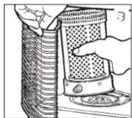
natural_image
Illustration of a hand inserting a textured object into a cylindrical container (no text or symbols visible)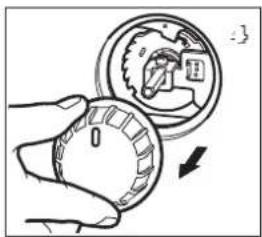

natural_image
Illustration of a hand using a tool to adjust a circular component (no text or symbols visible)
natural_image
Illustration of a portable air conditioner with a hand holding the fan (no text or symbols visible)
natural_image
Line drawing of a hand using a tool to press down a mechanical component (no text or symbols)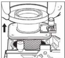
natural_image
Technical diagram of a mechanical assembly with no visible text or symbols
natural_image
Line drawing of a mechanical assembly with a hand operating a tool (no text or symbols)
natural_image
Diagram of a mechanical device with a hand pressing a button (no text or symbols present)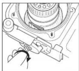
natural_image
Mechanical assembly diagram showing a rotating component with a curved arrow indicating rotation (no text or symbols present)
natural_image
Simple line drawing of a fish being cut with a fork (no text or symbols)natural_image
Hand holding a coiled device with a handle, no visible text or symbols


natural_image
Diagram of a hand operating a mechanical device with a tool, no visible text or symbols
natural_image
Line drawing of a hand using a tool to press or install a mechanical component (no text or symbols visible)
natural_image
Mechanical assembly diagram showing a presser pressing a component with a downward arrow indicating motion (no text or symbols present)
natural_image
Line drawing of a hand pressing down on a small component (no text or symbols)
natural_image
Hand operating a mechanical device with a rotating knob (no text or symbols visible)
natural_image
Diagram of a hand holding a tool with an arrow indicating direction (no text or symbols present)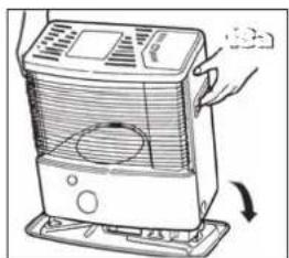
natural_image
Illustration of a hand operating a portable electric heater with a cooling fan (no text or symbols visible)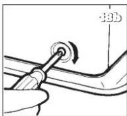
natural_image
Close-up of a hand holding a tool with a circular knob, no visible text or symbols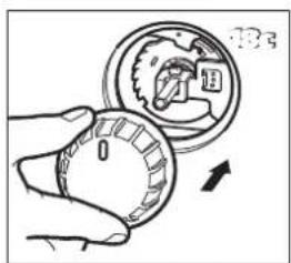
natural_image
Diagram of a cylindrical device with a perforated top and base, connected to a knob (no text or symbols visible)
natural_image
Line drawing of a hand using a tool to press or press a container on a tray (no text or symbols)
R DATABLAD
(a) Leverandørens navn / varemerke TOYOTOMI Europe Sales B.V.
(b) Modell RS-240
(c) Energieffektivitetsklasse A
zibro made by TÓYÓTÓMI
Distributed in Europe by TOYOTOMI EUROPE SALES B.V.
This product is not suitable for primary heating purpose.
Should you require further information or should particular problems occur that are not dealt with in this operating manual, please visit our website www.toyotomi.eu or contact our Sales Support (you find its phone number on www.toyotomi.eu)
Kerosun, Toyostove, Toyoset, Toyotomi and Zibro for the use of paraffin heaters are all registered trademarks of TOYOTOMI Co., Ltd. - Japan.
Zibro brand paraffin heaters are made in JAPAN and imported by Toyotomi Europe Sales b.v.


- TOYOTOMI EUROPE SALES B.V.
- GENERAL DIRECTIONS FOR USE
- WHAT YOU NEED TO KNOW IN ADVANCE
- ALWAYS MAKE SURE THAT THERE IS SUFFICIENT VENTILATION
- DO NOT
- THE RIGHT FUEL
- MANUAL
- A INSTALLING THE HEATER
- B FILLING FUEL
- C IGNITING THE HEATER
- D BURNING OF THE HEATER
- E SWITCHING OFF THE HEATER
- F MALFUNCTION, CAUSES AND SOLUTIONS
- THE HEATER DOES NOT IGNITE
- IRREGULAR FLAME AND/OR SOOT AND/OR SMELLS
- THE HEATER SLOWLY EXTINGUISHES
- THE HEATER REMAINS BURNING LOW
- THE HEATER IS BURNING TOO HIGH
- G MAINTENANCE
- THE BATTERIES
- THE WICK
- ELECTRODES
- THE FUEL FILTER
- H STORAGE (END OF THE HEATING SEASON)
- TRANSPORTATION
- K WARRANTY PROVISIONS
- REPLACEMENT OF THE WICK
- M PRODUCT FICHE
- GEBRAUCHSANWEISUNG
- J TECHNISCHE DATEN
- PRODUKTDATENBLATT
- LE COMBUSTIBLE APPROPRIÉ
- MANUEL
- A INSTALLATION DE L'APPAREIL
- B REMPLISSAGE DU COMBUSTIBLE
- CALLUMAGE DE L'APPAREIL
- FLAMME INSTABLE ET/OU SUIE ET/OU ODEUR.
- L'APPAREIL S'ÉTEINT LENTEMENT.
- CONDITIONS DE GARANTIE
- FICHE PRODUIT
- WAT U VOORAF MOET WETEN
- ALTIJD VOLDOENDE VENTILEREN
- HANDLEIDING
- A HET INSTALLEREN VAN DE KACHEL
- B VULLEN MET BRANDSTOF
- DE KACHEL BLIJFT LAAG BRANDEN.
- H OPSLAG (EINDE STOOKSEIZOEN)
- PRODUCTKAART
- A INSTALACION DE LA ESTUFA
- B LLENAR DE COMBUSTIBLE
- G MANTENIMIENTO
- TRANSPORTE
- K CONDICIONES DE GARANTÍA
- M FICHA DE PRODUCTO
- MANUALE
- B RIFORNIMENTO DEL COMBUSTIBILE
- C ACCENSIONE DELLA STUFA
- D LA COMBUSTIONE DELLA STUFA
- E SPEGNIMENTO DELLA STUFA
- G LA MANUTENZIONE
- M SCHEDA PRODOTTO
- B ABASTECIMENTO DE COMBUSTÍVEL
- E DESLIGAR O AQUECEDOR
- G MANUTENÇÃO
- K CONDIÇÕES DE GARANTIA
- M FICHA DE PRODUTO
- HVAD MAN F∅RST SKAL VIDE
- S∅RG ALTID FOR TILSTRÆKKELIG VENTILATION
- VEJLEDNING
- A INSTALLATION AF OVNEN
- B PÄFYLDNING AF BRÄNDSTOF
- F FUNKTIONSFEJL, ÅRSAGER OG L∅SNINGER
- G OM VEDLIGEHOLDELSEN
- TRANSPORT
- K GARANTIBETINGELSERNE
- UDSKIFTNING AF VÄGEN
- DATABLAD
- HÅNDBOK
- A INSTALLERE OVNEN
- K GARANTIBETINGELSER
- R DATABLAD
- zibro made by TÓYÓTÓMI
- Distributed in Europe by TOYOTOMI EUROPE SALES B.V.
Brand : ZIBRO
Model : RS 240
Category : Heating