LMRRUL - Photoelectric sensor LIFT-MASTER - Free user manual and instructions
Find the device manual for free LMRRUL LIFT-MASTER in PDF.

| Product type | Monitored retroreflective photoelectric sensor |
| Brand | LIFT-MASTER |
| Model | LMRRUL |
| Maximum range | 15.2 m (50 ft) |
| Sensor power supply | 6.8 V DC, 20 mA |
| Heater power supply | 10 to 40 V DC or 8 to 28 V AC, 2 W max |
| Operating temperature | -40 °C to 65 °C (-40 °F to 149 °F) |
| Protection rating | NEMA 4X |
| Sensor dimensions with cover | 5.81 cm (W) x 9.45 cm (H) x 7.01 cm (D) |
| Reflector dimensions with cover | 6.62 cm (W) x 11.98 cm (H) x 5.08 cm (D) |
| Cable length | 3 m (10 ft) |
| Main functions | Monitored entrapment protection, LED alignment (red/blue), built-in thermostat-regulated heater |
| Maintenance and cleaning | Clean the sensor and reflector gently with a soft damp cloth; check alignment monthly |
| Safety | Disconnect power before installation; mount vertically; max. height 11.4 cm (doors) or 66 cm (barriers); use only the supplied reflector |
| Spare parts and accessories | LMSGBP mounting plate, LMEHUL extended cover, APOW1 transformer, K41-39254 reflector kit |
| Warranty | 2 years |
Frequently Asked Questions - LMRRUL LIFT-MASTER
User questions about LMRRUL LIFT-MASTER
0 question about this device. Answer the ones you know or ask your own.
Ask a new question about this device
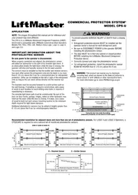
Download the instructions for your Photoelectric sensor in PDF format for free! Find your manual LMRRUL - LIFT-MASTER and take your electronic device back in hand. On this page are published all the documents necessary for the use of your device. LMRRUL by LIFT-MASTER.
USER MANUAL LMRRUL LIFT-MASTER
MONITORED RETRO-REFLECTIVE PHOTOELECTRIC SENSOR Model LMRRUL
Introduction
The LiftMaster® Retro-Reflective Photoelectric Sensor provides non-contact monitored entrapment protection. For use with LiftMaster® UL Listed gate operators. The sensor is a UL Recognized Component and meets UL 325 requirements. Monitored external entrapment protection devices MUST be installed at each Entrapment Zone. Refer to gate operator manual for compatibility with LMRRUL sensor.
Specifications
Max Range: 50 ft. (15.2 m)
Sensor Dimensions with Hood:
2.29"W x 3.72"H x 2.76"D
Reflector Dimensions with Hood:
2.61"W x 4.72"H x 2"D
Cable Length: 10 ft. (3 m)
Operating Temperature: -40°C to 65°C
(-40°F a 149°F)
Outdoor Rating: Nema 4X
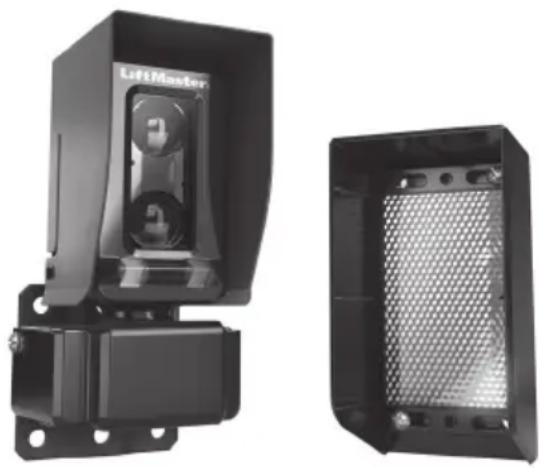
natural_image
Two black industrial electronic device components, one with a 'LiftMaster' label and the other showing a mesh grille (no text or symbols on main body)Input voltage:
Sensor: Black/red wires 6.8 VDC, 20mA
Heater: Green/white wires 10-40VDC or 8-28 VAC, 2 watts max., 170mA @ 12 VDC/VAC,
85mA @ 24 VDC/VAC
Heater: Thermostatically controlled, NOT
recommended for solar applications
WARNING
To prevent possible SERIOUS INJURY or DEATH from a closing gate or door:
- Read and follow ALL instructions.
- Be sure to DISCONNECT ALL POWER to the operator BEFORE installing the photoelectric sensor.
- The gate or door MUST be in the fully opened or closed position BEFORE installing the LiftMaster ^® Monitored Entrapment Protection device.
- Correctly connect and align the photoelectric sensor.
- Install the photoelectric sensor so that the center of the sensor window is NO HIGHER than 4-1/2" (11.4 cm) above the floor for door operators and 26" (66 cm) above grade for gate operators.
- Monitored external entrapment protection devices MUST be installed per the operator installation manual at each Entrapment Zone.
- The sensor and reflector MUST be mounted vertically.
- Use the provided refl ector ONLY.
- Test the gate operator and ALL photoelectric sensors monthly. Replace ANY damaged devices.
- SAVE THESE INSTRUCTIONS.
Carton Inventory
• Photoelectric sensor with hood and bracket
• Reflector with hood and bracket
- Wire cover
- Screws 8-32x1" (4)
- Lock nuts 8-32 (4)
- Screws 8-32x3/8" (2)
- Thread-locking screws 10-32x1" (2)
- Screws 1/4"-20x1-1/4" (6)
- Lock nuts 1/4"-20 (2)
- M3 screw (1)
- Set screw 10-32x3/8" (1)
Tools Needed
• Philips screwdriver
• 1/8" Allen wrench
- 7/16" socket
- 11/32" socket
- 5/32" Allen key
• 3/32" Allen key
Installation
IMPORTANT: The sensor and the reflector MUST be mounted vertically. Disconnect ALL power to the operator.
- Attach the mounting bracket to the post with 1/4"-20 screws. Drill a hole in the post through the center hole in the bracket. Optional: If installing to a square post or flat surface, you may attach the sensor bracket directly to the post without using the mounting bracket. Make sure the location of the sensor follows the specified measurements. If installing multiple sensors in close proximity, mount the sensors on opposite sides to avoid crosstalk.
- Slide the bottom sensor bracket onto the studs of the mounting bracket and secure with 1/4"-20 lock nuts. Make sure the bracket legs are facing down.
- Loosely attach the top sensor bracket with 10-32x1" thread-locking screws. Make sure the slots are facing up.
- Place the sensor in the bracket and tighten the screws just enough to allow the sensor to rotate inside the bracket.
- Slide the hood over the sensor until it snaps into place. Secure hood with the M3 screw. The hood MUST be installed on the sensor.
- Route wires through the center hole of the mounting bracket and into the post. Optional: Use conduit with NEMA 4X compatible 1/2"-14 NPT fi tting (not provided).
- Place the refl ector in the refl ector hood.
- Secure the refl ector and hood to the bracket with 8-32x1" screws. Secure the bottom of the refl ector to the hood with 8-32x1" screws.
- Mount the reflector a minimum of 3 ft. (.9 m) and maximum of 50 ft. (15.2 m) away from the sensor.
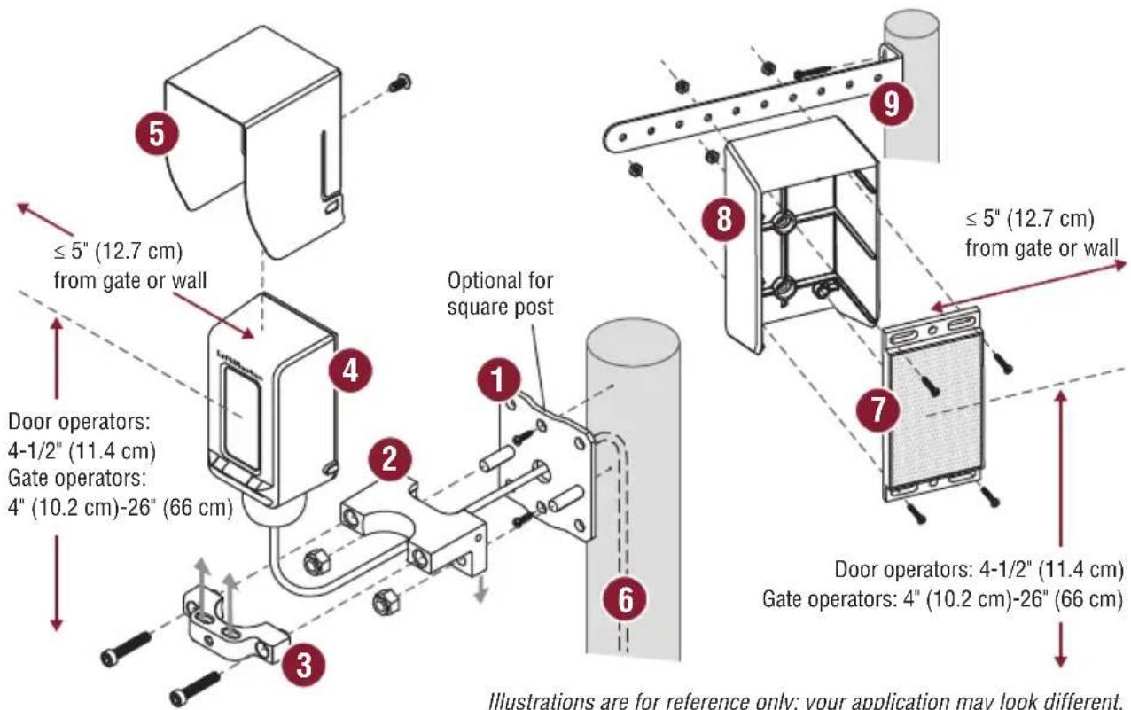
text_image
≤ 5" (12.7 cm) from gate or wall Door operators: 4-1/2" (11.4 cm) Gate operators: 4" (10.2 cm)-26" (66 cm) Optional for square post ① ② ③ ④ ⑤ ⑥ ⑦ ⑧ ⑨ ≤ 5" (12.7 cm) from gate or wall Door operators: 4-1/2" (11.4 cm) Gate operators: 4" (10.2 cm)-26" (66 cm) Illustrations are for reference only; your application may look different.Illustrations are for reference only; your application may look different.
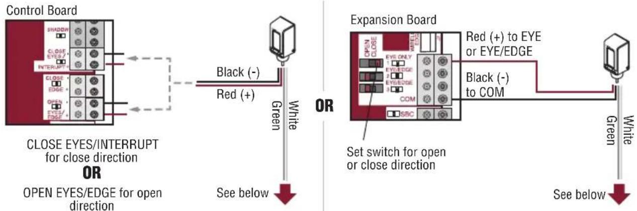
Wiring
Sensor wiring (red and black wires): Wire the photoelectric sensors (red [+] and black [-] wires) to the appropriate inputs on the operator or expansion board as shown.
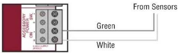
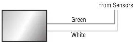
Heater wiring (green and white wires):
- OPTION 1 - Connect to the ACCESSORY POWER ON terminal on the control board (NOT polarity specific).
- OPTION 2 - Connect to an external 12V to 24V DC or AC power supply (not provided) with adequate current to power all sensors.
- OPTION 3 - For use with battery backup. Connect to ACCESSORY POWER ON and AUX RELAY terminals. Set AUX RELAY switches as shown. In this configuration, the heater will switch off during a power failure to extend the battery life.
DO NOT overload the accessory power output on the control board or the external power supply.
NOTE: Heater feature is not recommended for ANY solar installations.
Sensor Wiring
text_image
Control Board SHADON CLOSE EYES/ INTERRUPT+ CLOSE EDGE + OPEN EYES/ EDGE + CLOSE EYES/INTERRUPT for close direction OR OPEN EYES/EDGE for open direction Black (-) Red (+) Green White See below OR Expansion Board OPEN CLOSE EYES ONLY 1 EYE/EDGE 2 EYE/EDGE 3 COM SBC Red (+) to EYE or EYE/EDGE Black (-) to COM Set switch for open or close direction Green White See belowHeater Wiring
OPTION 1
Control board
ACCESSORY POWER ON
Max. draw 500 mA
text_image
ACCESSORY ON SW. GAS 11.0MPWR 49/23 From Sensors Green WhiteOR
OPTION 2
External 12V to 24V DC or AC power supply (not provided) with adequate current to power all sensors
text_image
From Sensors Green WhiteOR
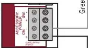
OPTION 3
For use with battery backup
Control board
ACCESSORY
POWER ON
Max. draw 500 mA
text_image
ACCESSORY POWER ON + SW- + - Ground power greeBlack (not provided)
White
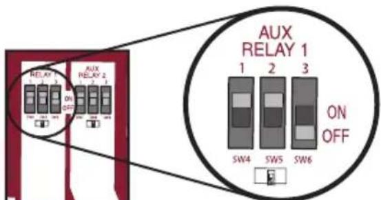
text_image
AUX RELAY 1 1 2 3 ON OFF SW4 SW5 SW6Expansion board
aux relay
AUX RELAY will switch off during power failure
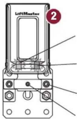
Alignment
Reconnect power to the operator.
- Align the sensor. The red LED indicates a misaligned or blocked sensor. The blue LED indicates signal strength. Slow blinking indicates weak signal. Fast blinking indicates stronger signal. Solid blue LED indicates optimal alignment.
- When the sensor is optimally aligned, tighten the sensor bracket screws to secure the sensor in place (about 24in-lb of torque). For extra security, tighten with the set screw until it grips the sensor.
- Place the wire cover onto the sensor bracket. Make sure the tabs on the wire cover slide into the slots on the top of the sensor bracket. Secure the wire cover with 8-32x3/8" screws. Wire cover is NOT intended for use with conduit installations.
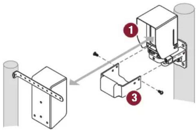
text_image
Technical diagram showing three-step installation of a mechanical bracket assembly with labeled components
text_image
LeftMaster 2Red LED indicates misaligned or blocked sensor
Blue LED Solid blue indicates optimal alignment
Sensor bracket screw
Set screw
Test
Test ALL installed sensors for proper operation. Place an obstruction in the sensor beam path and run the operator. The gate will stop and reverse. If the gate does not stop and reverse, refer to Troubleshooting below. Perform the test with the obstruction in three locations:
• Halfway between the reflector and sensor
- Near the sensor
- Near the reflector
Troubleshooting
| Symptom Possible Cause Solution | ||
| Obstruction does not cause the gate to reverse | 1. Using incorrect refl ector2. Refl ector is mounted horizontally | 1. USE THE PROVIDED REFLECTOR ONLY.2. Refl ector MUST be mounted vertically |
| Gate does not move | 1. Minimum number of entrapment devices not installed2. Sensor is obstructed | 1. Review sensor connections. Slide gate operators require a minimum or two devices; one in the close and one in the open direction.2. Check for obstructions. |
| Solid Red LED 1. Sensor is not properly aligned2. Sensor is too far from refl ector3. Refl ector or sensor lens is dirty4. Object is obstructing beam5. Condensation on refl ector or sensor lens | 1. Align the sensor until the blue light is solid2. Decrease the distance between the sensor and refl ector3. Gently clean the sensor and refl ector with a soft damp towel4. Remove any objects obstructing beam5. Gently clean the sensor and refl ector with a soft towel; make sure sensor heater is connected. | |
| Blinking Blue LED 1. | Sensor is not optimally aligned2. Sensor is too far from refl ector3. Refl ector or sensor lens is dirty | 1. Align the sensor until the blue light is solid2. Decrease the distance between the sensor and refl ector3. Gently clean the sensor and refl ector with a soft damp towel |
| Blinking Red LED Indirect wiring or over voltage Check for proper connection of sensor wiring. | ||
| Red/Blue LEDs blinking together | Internal memory fault Disconnect all power, wait 15 seconds, then reconnect power.If issue continues, replace sensor. | |
| Red/Blue LEDs alternate blinking | Internal fault Disconnect all power, wait 15 seconds, then reconnect power.If issue continues, replace sensor. | |
Accessories
LMSGBP: Photoelectric sensor gang box plate
LMEHUL: Photoelectric sensor extended hood
APOW1: Plug in transformer
K41-39254: Reflector, bracket, and hardware
Warranty
LiftMaster® warrants to the first consumer purchaser of this product that it is free from defect in materials and/or workmanship for a period of 2 years from the date of purchase.
NOTICE: This device complies with Part 15 of the FCC rules and Industry Canada's license-exempt RSSs. Operation is subject to the following two conditions: (1) this device may not cause harmful interference, and (2) this device must accept any interference received, including interference that may cause undesired operation. Any changes or modifications not expressly approved by the party responsible for compliance could void the user's authority to operate the equipment.
This device has been tested and found to comply with the limits for a Class B digital device, pursuant to part 15 of the FCC rules and Industry Canada ICES standard. These limits are designed to provide reasonable protection against harmful interference in a residential installation. This equipment generates, uses and can radiate radio frequency energy and, if not installed and used in accordance with the instructions, may cause harmful interference to radio
communications. However, there is no guarantee that interference will not occur in a particular installation. If this equipment does cause harmful interference to radio or television reception, which can be determined by turning the equipment off and on, the user is encouraged to try to correct the interference by one or more of the following measures:
- Reorient or relocate the receiving antenna.
- Increase the separation between the equipment and receiver.
- Connect the equipment into an outlet on a circuit different from that to which the receiver is connected.
- Consult the dealer or an experienced radio/TV technician for help.
natural_image
Two black industrial electronic device components, one with a 'LiftMaster' label and the other showing a mesh grille (no text or symbols on main body)text_image
Technical diagram showing assembly steps of a mechanical bracket with labeled components 1 and 3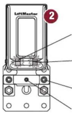
text_image
LiftMaster 2natural_image
Two black industrial electronic device components, one with a circular component labeled 'LiftMaster', the other showing a mesh grille (no visible text or symbols)text_image
Technical diagram showing mechanical assembly steps with labeled components 1 and 3