041DJ003MC - Garage door LIFT-MASTER - Free user manual and instructions
Find the device manual for free 041DJ003MC LIFT-MASTER in PDF.

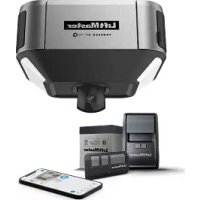
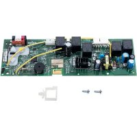
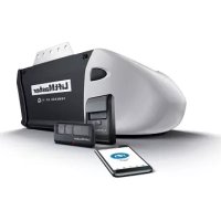
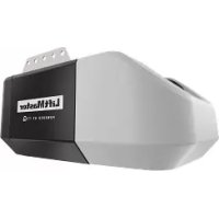
| Product Type | Replacement logic board for garage door opener |
| Brand | LIFT-MASTER |
| Model | 041DJ003MC |
| Compatibility | Replaces 050DCRJWF; compatible with LiftMaster Security+ 2.0 and myQ openers |
| Power Supply | 24 V DC (via opener battery) |
| Main Functions | Travel programming, force adjustment, remote and keypad management, myQ Wi-Fi connection, smart LED light control |
| Number of Programmable Remotes | Up to 40 Security+ 2.0 remotes |
| Safety Sensors | Protector System® (safety reversal); requires compatible safety reversal sensors |
| Compatible Door Type | Sectional door (standard lift, high lift, vertical lift); door profiles 1 to 5 |
| Connectivity | Built-in Wi-Fi for myQ app; short antenna |
| Operating Temperature | -20 °C to 50 °C (estimated) |
| Safety | Complies with FCC Part 15 and Industry Canada RSS; avoid contact with circuit board during installation |
| Maintenance and Cleaning | Disconnect power before any intervention; use gloves and safety glasses when changing battery |
| Spare Parts and Repairability | Replacement logic board; battery sold separately; parts available via LiftMaster |
| Warranty | Consult the dealer or LiftMaster for warranty conditions |
| Dimensions (estimated) | Approximately 15 x 10 x 2 cm |
| Weight (estimated) | Approximately 100 g |
Frequently Asked Questions - 041DJ003MC LIFT-MASTER
User questions about 041DJ003MC LIFT-MASTER
0 question about this device. Answer the ones you know or ask your own.
Ask a new question about this device
Download the instructions for your Garage door in PDF format for free! Find your manual 041DJ003MC - LIFT-MASTER and take your electronic device back in hand. On this page are published all the documents necessary for the use of your device. 041DJ003MC by LIFT-MASTER.
USER MANUAL 041DJ003MC LIFT-MASTER
NOTE: Please read these instructions as programming may be different from older programming.
WARNING
To prevent possible SERIOUS INJURY or DEATH:
- Disconnect ALL electric and battery power BEFORE performing ANY service or maintenance.
CAUTION
To prevent damage to the receiver/logic board, DO NOT touch printed circuit board of replacement receiver/logic board during installation. ALWAYS wear protective gloves and eye protection when changing the battery or working around the battery compartment.

WARNING: This product can expose you to chemicals including lead, which are known to the State of California to cause cancer or birth defects or other reproductive harm. For more information go to www.P65Warnings.ca.gov.
NOTICE: This device complies with Part 15 of the FCC rules and Industry Canada's license-exempt RSSs. Operation is subject to the following two conditions: (1) this device may not cause harmful interference, and (2) this device must accept any interference received, including interference that may cause undesired operation.
Any changes or modifications not expressly approved by the party responsible for compliance could void the user's authority to operate the equipment.
This device must be installed to ensure a minimum 20 cm (8 in.) distance is maintained between users/bystanders and device.
This device has been tested and found to comply with the limits for a Class B digital device, pursuant to part 15 of the FCC rules and Industry Canada ICES standard. These limits are designed to provide reasonable protection against harmful interference in a residential installation. This equipment generates, uses and can radiate radio frequency energy and, if not installed and used in accordance with the instructions, may cause harmful interference to radio communications. However, there is no guarantee that interference will not occur in a particular installation. If this equipment does cause harmful interference to radio or television reception, which can be determined by turning the equipment off and on, the user is encouraged to try to correct the interference by one or more of the following measures:
• Reorient or relocate the receiving antenna.
- Increase the separation between the equipment and receiver.
- Connect the equipment into an outlet on a circuit different from that to which the receiver is connected.
- Consult the dealer or an experienced radio/TV technician for help.
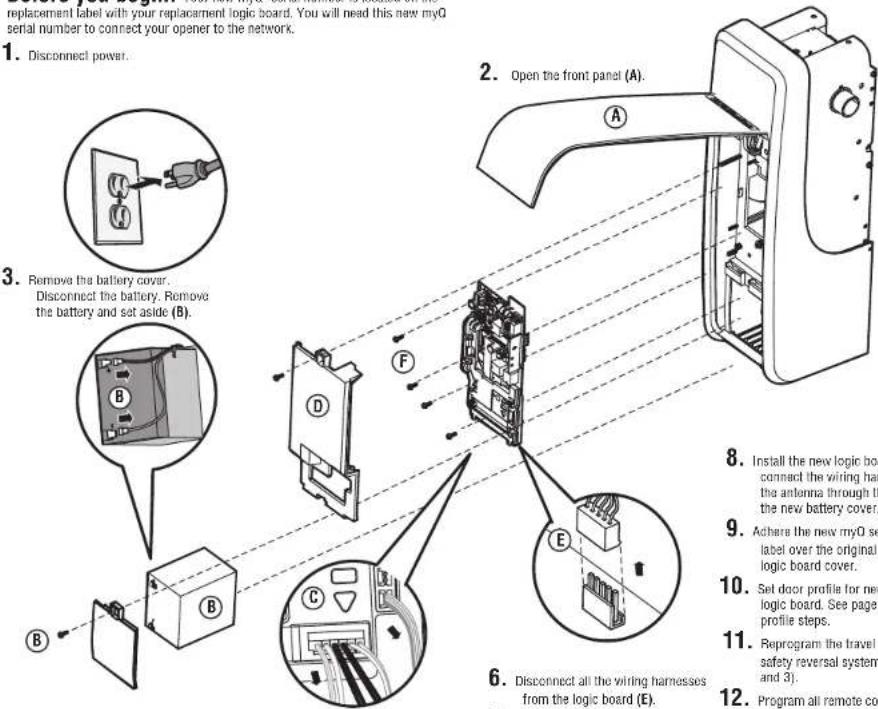
Before you begin. Your new myQ serial number is located on the replacement label with your replacement logic board. You will need this new myQ serial number to connect your opener to the network.
- Disconnect power.
text_image
replacement label with your replacement logic board. You will need this new myQ serial number to connect your opener to the network. 1. Disconnect power. 2. Open the front panel (A). 3. Remove the battery cover. Disconnect the battery. Remove the battery and set aside (B). 4. 5. 6. Disconnect all the wiring harnesses from the logic board (E). 7. 8. Install the new logic board connect the wiring har the antenna through the the new battery cover. 9. Achie the new myQ se label over the original & logic board cover. 10. Set door profile for new logic board. See page 1 profile steps. 11. Reprogram the travel a safety reversal system and 3). 12. Program all remote con- Disconnect the wires coming from the safety reversing sensors, door control, door lock and cable tension monitor from the logic board (C).
-
Remove the logic board cover (D).
-
Disconnect all the wiring harnesses from the logic board (E).
-
Remove the four screws securing the logic board, remove the logic board (F), and discard.
-
Install the new logic board and connect the wiring harnesses. Route the antenna through the channel in the new battery cover.
- Achere the new myO serial number label over the original label on the logic board cover.
- Set door profile for new replacement logic board. See page 2 to set door profile steps.
- Reprogram the travel and test the safety reversal system (see pages 2 and 3).
- Program all remote controls and keyless entries (see page 4).
- Use the myQ app to add the new myQ serial number to your account.
text_image
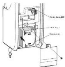
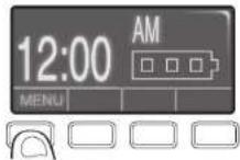
Battery Suffix LCD Control panel Control panel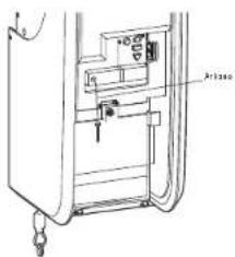
text_image
Technical diagram of a device with labeled components and directional arrows indicating movement or flowNOTE: Be sure the short antenna is not pinched by the battery door and held in place as shown.
Adjustment
Identify Door Profile
To identify the door profile number, measure the full drum diameter based on the images below.
NOTE: This step is important to ensure the proper operation of the unit. To view a video demonstration of how to identify and set the door profile, scan the QR code.

WARNING
To prevent possible SERIOUS INJURY or DEATH, follow instructions to select and set door profile for safe and proper operation.
WARNING
To prevent possible SERIOUS INJURY or DEATH, after ANY changes to the door profile, reprogram limits.
Set Door Profile
- To enter Set Door Profile mode, press and hold the black button for one second. The UP and DOWN buttons turn a solid color.
- To set Door Profile, press the UP and DOWN buttons. The Learn LED button blinks and beeps as you change the setting.
- The number of Learn LED button blinks indicates which profile you have selected. There is no preset door profile setting.
- Press and release the Black button to set the Door Profile. This process is now complete. Proceed to the Travel Learn mode.
EXITING DOOR PROFILE NUMBER SETTING
If there is no selection within 4.5 minutes, the Door Profile selection mode will be cancelled with a long beep.
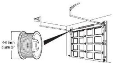
Standard Lift Sectional Door
- Door Profile 1 = Standard to Heavy Weight Door* with a 4" drum (Recommended).
- Door Profile 2 = Light Weight Door with a 4" drum.
- Door Profile 3 = Heavy Weight Door* with a 6" drum.
- Door Profile 4 = Light Weight Door with a 6" drum.
* NOTE: Drum sizes may vary by manufacturer.
For Standard Lift Sectional Doors:
- Drums less than or equal to 5", use 4" drum.
- Drums more than 5", use 6" drum.
Standard to Heavy Weight doors are those with solid wood interiors, wood veneer exteriors, glass windows, insulation, and/or decorations.
High Lift Door
- Door Profile 5 = Tapered drum with tracks that raise to a higher elevation
text_image
4-6 inch diameter
text_image
Learn LED Yellow Button Battery LED UP Button Black Button DOWN Button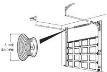
text_image
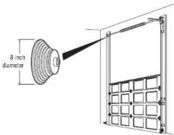
8 inch diameterVertical Lift Sectional Door
- Door Profile 5 = Tapered Drum with tracks raising vertically above the opening.
text_image
8 inch diameterAdjustment
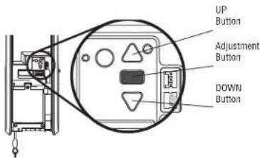
Program the Travel
Travel limits regulate the points at which the door will stop when moving up or down.
While programming the travel, the UP and DOWN buttons can be used to move the door as needed. During the Automatic Force Setup, the door will automatically open and close.
- Press and hold the Adjustment Button until the UP Button begins to flash and/or a beep is heard. The Safety Reversing Sensors will be disconnected during the Program the Travel process.
- Press and hold the UP Button until the door is in the desired UP position.
- Once the door is in the desired UP position press and release the Adjustment Button. The garage door opener lights will flash twice and the DOWN Button will begin to flash.
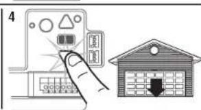
- Press and hold the DOWN Button until the door is in the desired DOWN position.
- Once the door is in the desired DOWN position press and release the Adjustment Button. The garage door opener lights will flash twice. Program the Travel is now complete. If the garage door opener lights flash 5 times, then programming has timed out and the Travel Limits have not been set. Please restart the Program the Travel process.
Automatic Force Set Up
Once both the up and down positions have been manually set, the Safety Reversing Sensors will reconnect and become operational. Then, the opener will enter a force-sensing operation by automatically moving the door open and close. The garage door opener will sound an audible and visual alert before automatically opening and closing the door. The garage door opener will beep three times, confirming that the Automatic Force Setup completed successfully. Adjustment is complete.
If you hear one long beep after the door attempts to move, then the Automatic Force Set Up has not completed successfully. Please start over at step 1 of Program the Travel.
text_image
UP Button Adjustment Button DOWN Button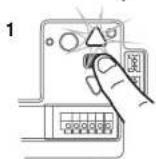
text_image
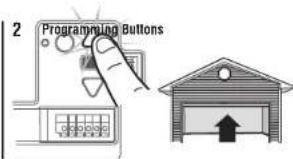
2 Programming Buttons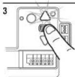
text_image
4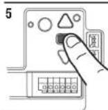
WARNING
To prevent possible SERIOUS INJURY or DEATH, after ANY changes to the door profile, reprogram limits.
WARNING
Without a properly installed safety reversal system, persons (particularly small children) could be SERIOUSLY INJURED or KILLED by a closing garage door.
- Incorrect adjustment of garage door travel limits will interfere with proper operation of safety reversal system.
- After ANY adjustments are made, the safety reversal system MUST be tested. Door MUST reverse on contact with 1-1/2" high (3.8 cm) object (or 2x4 laid flat) on floor.
CAUTION
To prevent damage to vehicles, be sure fully open door provides adequate clearance.
Adjustment
Test the Safety Reversal System
- With the door fully open, place a 1-1/2 inch (3.8 cm) board (or a 2x4 laid flat) on the floor, centered under the garage door.
- Press the remote control push button to close the door. The door MUST reverse when it makes contact with the board.
If the door stops but does not reverse:
-
Repeat Program the Travel (see Adjustment).
-
Repeat the Safety Reversal test.
If the test continues to fail, call a trained door systems technician.
Test the Protector System®
- Open the door. Place an obstruction in the path of the door.
- Press the remote control push button to close the door. The door will not move more than an inch (2.5 cm).
The garage door opener will not close from a remote control if the LED in either safety reversing sensor is off (alerting you to the fact that the sensor is misaligned or obstructed).
If the garage door opener closes the door when the safety reversing sensor is obstructed (and the sensors are no more than 6 inches [15 cm] above the floor), call for a trained door systems technician.
Synchronize the Door Control
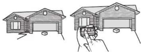
To synchronize the door control to the garage door opener, press the push bar until the garage door opener activates (it may take up to 3 presses). Test the door control by pressing the push bar. Each press of the push bar will activate the garage door opener.
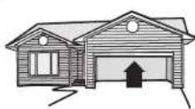
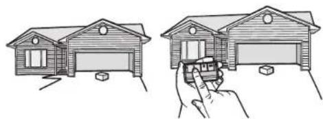
1.2.
natural_image
Illustration of two house models: one with a roof and window, the other with a hand holding a door (no text or symbols)1.2.
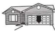
natural_image
Illustration of two hand-drawn house diagrams showing front and side views, with no text or symbols present.WARNING
Without a properly installed safety reversal system, persons (particularly small children) could be SERIOUSLY INJURED or KILLED by a closing garage door.
• Safety reversal system MUST be tested every month.
- After ANY adjustments are made, the safety reversal system MUST be tested. Door MUST reverse on contact with 1-1/2" (3.8 cm) high object (or 2x4 laid flat) on the floor.
WARNING
Without a properly installed safety reversing sensor, persons (particularly small children) could be SERIOUSLY INJURED or KILLED by a closing garage door.
Programming
Remote Control
Your remote control has been programmed at the factory to operate with your garage door opener. If the remote does not work or you would like to program additional devices, follow the programming steps below.
Up to 40 Security+ 2.0 ^xx remote controls can be programmed to the garage door opener. Older LiftMaster remote controls are NOT compatible. Programming can be done through the door control or the learn button on the garage door opener. To program additional accessories refer to the instructions provided with the accessory or visit LiftMaster.com. If your vehicle is equipped with a Homelink ^xx , you may require an external adapter depending on the make, model, and year of your vehicle. Visit www.homelink.com for additional information.
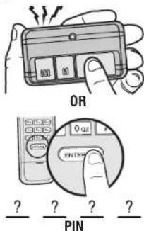
To add, reprogram, or change a 893LM remote control/877LM keyless entry pin using the door control
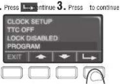
- Press the navigation button below 'MENU' to view the Features menu
- Use the navigation buttons to scroll to "PROGRAM".
- Select "REMOTE" or "KEYPAD" to program from the program menu.
- Remote Control: Press the button on the remote control that you wish to operate your garage door.
- Keyless Entry: Enter a 4-digit personal identification number (PIN) of your choice on the keyless entry keypad. Then press the ENTER button.
The garage door opener lights will flash (or two clicks will be heard) when the code has been programmed. Repeat the steps above for programming additional remote controls or keyless entry devices. If programming is unsuccessful, program the remote using the learn button.
Program a 893MAX remote control using the learn button on the garage door opener
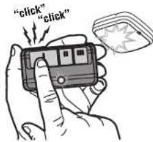
- Press and hold the program button on the remote control until the LED on the front of the remote control turns on.
- Press and release the remote control button you wish to use and then press any other button to exit programming.
- Press and release the Learn button on the garage door opener. The Learn LED will light. Within 30 seconds...
- Press the remote control button programmed in step 2 until the garage door opener light flashes or two clicks are heard.
To program other types of remote controls or keyless entries see the instructions included with the device or visit LiftMaster.com.
Add myQ serial number to myQ App
To program the Wi-Fi garage door opener to your network, refer to your owner's manual.
2
text_image
Press 3. Continue 3. Press to continue CLOCK SETUP TTC OFF LOCK DISABLED PROGRAM EXIT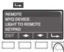
text_image
OR 0 or ENTER ? ? ? ? PIN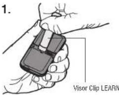
text_image
1. Visor Clip LEARN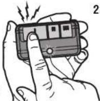
natural_image
Illustration of a hand holding a handheld electronic device with a finger, emitting sound waves (no text or symbols visible)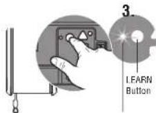
LED
text_image
"click" "click"Program the myQ Remote LED Light
Your garage door opener remote light has already been programmed at the factory to operate with your opener. Any additional or replacement remote lights will need to be programmed.
PROGRAM A DOOR OPENER TO THE myQ REMOTE LED LIGHT
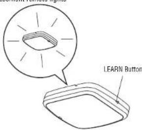
- Press the LEARN button on the light until the green LED comes ON.
- Press the LEARN button on the door opener. OR
On the Smart Control Panel ^① go to Menu > Program > myQ Accessory. - The code has been programmed when the remote light blinks once.
ADD THE myQ REMOTE LED LIGHT TO myQ ACCOUNT
- Press the LEARN button on the light until the green LED comes ON.
- Login to the myQ app and add the myQ Remote LED Light.
TO ERASE ALL PROGRAMMING FROM THE myQ REMOTE LED LIGHT
- Press and hold the LEARN button until the LED turns off (6-10 seconds). All programming is now erased.
text_image
LFARN Button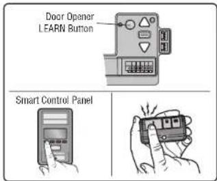
text_image
Door Opener LEARN Button Smart Control Panel114-5902-000
© 2023, The Chamberlain Group LLC
All rights reserved
Carte logique
Modèle 041DJ003MC
text_image
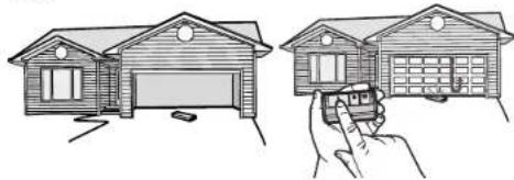
Technical diagram of a device with labeled components and directional arrows indicating flow or movementnatural_image
Line drawings of a two-story house and a hand holding a toy car (no text or symbols)1.2.
natural_image
Two line drawings showing a wooden house being held by a hand, with no text or symbols present.AVERTISSEMENT
natural_image
Illustration of a hand holding a small electronic device with vibration lines around it (no text or symbols)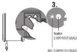
text_image
3. Beaton D'APPRENTISSAGE DEL D'APPRENTISSAGE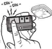
text_image
"Clic" "Clic"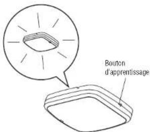
© 2023, The Chamberlain Group LLC
text_image
Diagram showing a device with labeled components and an inset view of a box, including a magnified view of the component.text_image
Technical diagram of a refrigerator interior with labeled components and parts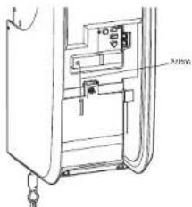
text_image
Airbagnatural_image
Line drawings of a two-story house and a hand holding a toy, both without any text or symbols.1.2.

natural_image
Two line drawings of a house with a hand holding a car, showing structural details (no text or symbols)ADVERTENCIA
CÓMO AÑADIR LA LUZ LED REMOTA myQ A LA CUENTA myQ
text_image
"click" "click"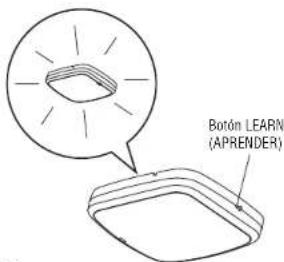
text_image
Botón LEARN (APRENDER)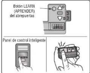
text_image
Botón LEARN (APRENDER) del abrepuertas Panel de control inteligente114-5902-000
© 2023, The Chamberlain Group LLC