81650 - Garage door LIFT-MASTER - Free user manual and instructions
Find the device manual for free 81650 LIFT-MASTER in PDF.

User questions about 81650 LIFT-MASTER
0 question about this device. Answer the ones you know or ask your own.
Ask a new question about this device
Download the instructions for your Garage door in PDF format for free! Find your manual 81650 - LIFT-MASTER and take your electronic device back in hand. On this page are published all the documents necessary for the use of your device. 81650 by LIFT-MASTER.
USER MANUAL 81650 LIFT-MASTER
Wi-Fi® Garage Door Openers
Chain Drive Models - 81600, 81602, 81640, 81650, 83650-267
Belt Drive Model - 81550
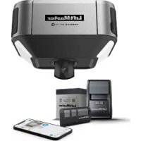
natural_image
Exterior view of a LiftMaster robotic device (no visible text or symbols on body)- Please read this manual and the safety materials caref
- The door WILL NOT CLOSE unless the Protector System connected and properly aligned.
- Periodic checks of the garage door opener are required to ensure safe operation.
- This garage door opener is ONLY compatible® with myC Security+ 2® accessories.
- DO NOT install on a one-piece door if using devices features providing unattended close. Unattended devices features are to be used ONLY with sectional doors.
- Attach warning labels to the location indicated on label
Download the myQ® App


Download on the App Store
Available on most iOS and Android Devices
LiftMaster
300 Windsor Drive
Oak Brook, IL 60523
LiftMaster®
Table of Contents
Preparation 3
Carton Inventory: Models 81600, 81602, 81640, 81650, and 83650-267 6
Carton Inventory: Model 81550...7
Assembly .8
Models 81600, 81602, 81640*, 81650, and 83650-267...8
Model 81550...9
Installation ..10
Install the Door Control..19
Install the Protector System...22
Power 26
Adjustments 29
Battery Backup...32
Operation 34
Maintenance 42
Troubleshooting 43
Accessories 45
Warranty 46
Automatic Garage Door Opener Safety & Maintenance Guide
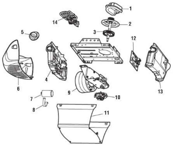
Repair Parts 49
Models 81600, 81602, 81640, 81650, and 83650-267...49
Models 81600 and 81602
Models 81640 and 81650
Model 83650-267 52
Model 81550 53
Model 81550 54
47
Preparation
myQ® Serial Number
Write down the following information for future reference:
myQ® Serial Number:
Product Serial Number:
Date of Purchase:

myQ® Serial Number
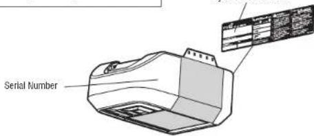
text_image
Serial NumberSafety Symbol and Signal Word Review
This garage door opener has been designed and tested to offer safe service provided operated, maintained and tested in strict accordance with the instructions and warnings this manual.
When you see these Safety Symbols and Signal Words on the following pages, they the possibility of serious injury or death if you do not comply with the warnings that accompany
them. The hazard may come from something mechanical or from electric shock. Read carefully.

WARNING
Mechanical

WARNING
Electrical
When you see this Signal Word on the following pages, it will alert you to the pc to your garage door and/or the garage door opener if you do not comply with the statements that accompany it. Read them carefully.

CAUTION

WARNING: This product can expose you to chemicals including lead, which are the State of California to cause cancer or birth defects or other reproductive more information go to www.P65Warnings.ca.gov
Preparation
Before You Connect with Your Smartphone
Monitor and control your garage door from anywhere using the myQ® App. You will need:
• Wi-Fi® enabled smartphone, tablet or laptop
- Broadband Internet Connection
• Wi-Fi® signal in the garage (2.4 GHz, 802.11b/g/n required)
- Password for your home network (router's main account, not guest network
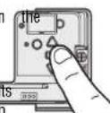
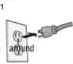
TEST THE WI-FI® SIGNAL STRENGTH
Make sure your mobile device is connected to your Wi-Fi® network. Hold your place where your garage door opener will be installed and check the Wi-Fi® sig
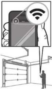
text_image
Diagram illustrating smart home connectivity with a smartphone displaying Wi-Fi icon and a person holding a device, alongside a grid layout.Check Signal Strength. If you see:


Wi-Fi signal is strong. The garage door opener will connect to your Wi-Fi network.

Wi-Fi signal is weak.
The garage door opener may connect to your
Wi-Fi network. If not, try one of the options
below to improve the Wi-Fi signal:

No Wi-Fi signal.
The garage door opener will not be able to
connect to your Wi-Fi network. Try one of the
options below to improve the WI-FI signal
- Move your router closer to the garage door opener to minimize
interference from walls and other objects
• Buy a Wi-Fi range extender
Visit support.chamberlaingroup.com for more details.
For compatible router specifications and help, visit WiFiHelp.LiftMaster.com.
See page 36 to connect the garage door opener to a mobile device.
Check the Door
WARNING
To prevent possible SERIOUS INJURY or DEATH:
- ALWAYS call a trained door systems technician if garage door binds, sticks, or balance. An unbalanced garage door may NOT reverse when required.
- NEVER try to loosen, move or adjust garage door, door springs, cables, pulley or their hardware. ALL of which are under EXTREME tension.
mobile Disable ALL lacks and remove ALL ropes connected to garage door BEFORE instal mal strength, operating garage door opener to avoid entanglement.
- DO NOT install on a one-piece door if using devices or features providing un close. Unattended devices and features are to be used ONLY with sectional do
CAUTION
To prevent damage to garage door and opener:
- ALWAYS disable locks BEFORE installing and operating the opener.
• ONLY operate garage door opener at 120V, 60 Hz to avoid malfunction
Before you begin:
- Disable locks and remove any ropes connected to the garage door.
- Lift the door halfway up. Release the door. If balanced, it should stay in place, supported entirely by its springs.
- Raise and lower the door to check for binding or sticking if Everton door binds, sticks, or is out of balance, call a trained door system technician.
- Check the seal on the bottom of the door. Any gap between the floor and the bottom of the door must not exceed 1/4" (6 mm). Otherwise, the safety reversal system may not work properly.
- The opener should be installed above the center of the door. If there is a torsion spring or center bearing plate in the way of the header bracket, it may be installed within 4 feet (1.2 m) to the left or right of the door center. See page 11.
Preparation
Tools Needed
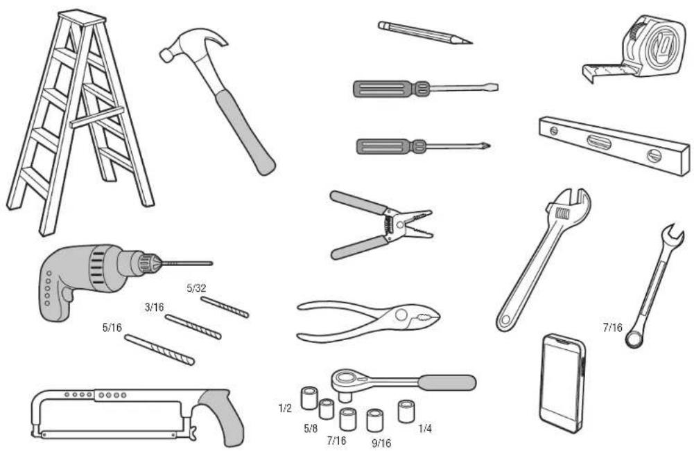
Preparation
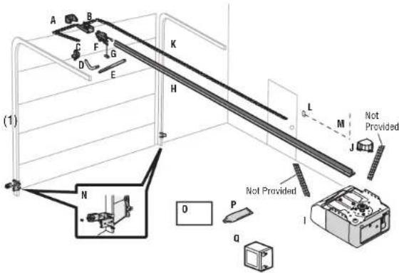
Carton Inventory: Models 81600, 81602, 81640, 81650, 83650-267
Accessories will vary depending on the garage door opener model purchased. De specific model, other accessories may be included with your garage door opener for these accessories will be attached to the accessory and are not included in this manual. The images throughout this manual are for reference and your product may look
For Square Rail see instructions included with the rail kit model LMSSRKIT.
A. Header bracket
B. Pulley and bracket
C. Door bracket
D. Curved door arm
G. Emergency release rope and handle
H. Rail
M. White and red/white wire
N. The Protector System Safety reversing sensors with white Receiving Sensor (1) and Safety S
O. Safety labels and literature
P. Rail grease
Q. Battery Backup (Model 81602 only)
SECURITY+ 2.⑨ ACCESSORIES
882LMW
Multi-Function Door Control
Models: 81600, 81602, 81650, 83650-267
883LMW
Push Button Door Control
Model: 81640
893LM
Remote Control
Models: 81600, 81602, 81650, 83650-267
891LM
Remote Control
Model: 81640


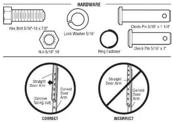
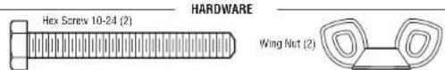
HARDWARE
Installation Door Control Hardware
Hearing bolt 5/16" 18 x 7/8" (4) Screw 6AB x 1" (2)
Large construction 6" -9 x 1-5/8" (2) Screw 6-32 x 1" (2)
Clevis Pin 5/16' x 2-3/4' (1) Drywall anchors (2)
different. Pin 5/16' x 1-1/4' (1)
Clevis Pin 5/16" x 1" (1)
Nut 5/16"-18 (4)
Lock washer 5/16" (4)
Self-threading screw 1/4'-14 x 5/8" (2)
Ring fastener (3)
Carriage bolt 1/4'-20 x 1/2' (2)
Wing nut 1/4'-20 (2)
Sensor
text_image
(1) A B C D E F G K H L M J Not Provided N O P Q I Not ProvidedPreparation
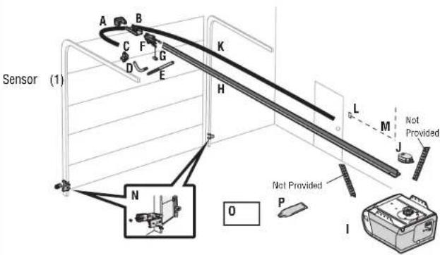
Carton Inventory: Model 81550
Accessories will vary depending on the garage door opener model purchased. De specific model, other accessories may be included with your garage door opener for these accessories will be attached to the accessory and are not included in this manual. The images throughout this manual are for reference and your product may look
A. Header bracket
B. Pulley and bracket
C. Door bracket
D. Curved door arm
G. Emergency release rope and handle
H. Rail
J. Sprocket cover with hex screws
K. Belt
L. Door control
M. White and red/white wire
N. The Protector System
Safety reversing sensors with white and white/black wire attached: Sending Receiving Sensor (1) and Safety Sensor Brackets (2)
O. Safety labels and literature
P. Rail grease
SECURITY+ 2.① ACCESSORIES
882LMW
Multi-Function Door Control
893LM
Remote Control


INSTALLATION HARDWARE
Hex, bolt 5/16"18 x 7/8" (4) Lock washer 5/16" (4)
Lag. screw 5/16'-9 x 1-5/8" (2) Self-threading screw 1/4"-14 x 5/8" (2)
Clevis "Pin 5/16" x 2-3/4" (1) Ring fastener (3)
Plevis. Pin 5/16" x 1-1/4" (1) Carriage bolt 1/4"-20 x 1/2" (2)
Clevis Pin 5/16' x 1' (1) Wing nut 1/4'-20 (2)
Nut 5/16'-18 (4)
DOOR CONTROL HARDWARE
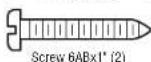
Screw 6AB x 1' (2)
Screw 6-32 x 1" (2)
Drywall anchors (2)
text_image
Sensor (1) A B C F G K D E H L M Not Provided N O P Not Provided IAssembly
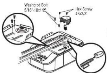
1 Attach the Rail to the Garage Door Opener
Models 81600, 81602, 81640*, 81650, and 83650-267
* Can be installed with a T-Rail or a Square Rail. For Square Rail assembly provided with the rail kit model LMSSRKIT. Once completed, return to this main instructions.
WARNING
To avoid possible SERIOUS INJURY to finger from moving garage door opener. • ALWAYS keep hand clear of sprocket while operating opener. • Securely attach sprocket cover BEFORE operating.
CAUTION
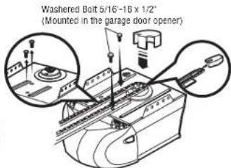
To avoid SERIOUS damage to garage door opener, use ONLY those bolts/fasteners mounted in the top of the opener.
NOTE: ONLY use the bolts removed from the garage door opener. Place the garage door opener on the packing material to prevent scratching.
- Remove the two bolts from the top of the garage door opener.
- Align the rail and the styrofoam over the sprocket. Cut the tape from the rail, chain, and styrofoam.
- Fasten the rail with the previously removed bolts.
- Position the chain around the garage door opener sprocket.
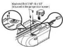
- Models 81600 and 81602: Attach the sprocket cover over the garage door opener sprocket and attach with hex screws.
Models 81640, 81650, and 83650-267: Install the sprocket cover by squeezing the sides and inserting the tabs into the slots on the garage door opener.
text_image
Washeder Bolt 5/16"-18x1/2" Hex Screw 48x3/8"Models 81600 and 81602 Models 81640, 81650, and 83650-267
text_image
Washeder Bolt 5/16'-18 x 1/2' (Mounted in the garage door opener)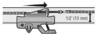
2 Tighten the Chain
- Loosen the inner nut and lock washer on the trolley threaded shaft. step8, Tightenstruction outer nut until the chain is a 1/2" above the base of the rail ual for of the installation
- Re-tighten the inner nut. Slack in the chain is normal when the door is closed. No readjustment is necessary. Sprocket noise can result if the chain is too loose. During future maintenance, ALWA emergency release handle to disconnect the trolley before adjusting the chain.
- Loosen the inner nut and lock washer on the trolley threaded shaft. Step 8, Tightenstruction outer nut until the chain is a 1/2" above the base of the rail ual for of the installation
- Re-tighten the inner nut.
Slack in the chain is normal when the door is closed. No readjustment is necessary. Sprocket noise can result if the chain is too loose. During future maintenance, ALWA emergency release handle to disconnect the trolley before adjusting the chain.
Assembly
1 Attach the Rail to the Garage Door Opener
Model 81550
WARNING
To avoid possible SERIOUS INJURY to finger from moving garage door opener:
• ALWAYS keep hand clear of sprocket while operating opener.
- Securely attach sprocket cover BEFORE operating.
CAUTION
To avoid SERIOUS damage to garage door opener, use ONLY those bolts/fasteners mounted in
the top of the opener.
NOTE: ONLY use the bolts removed from the garage door opener. Place the the packing material to prevent scratching.
-
Remove the two bolts from the top of the garage door opener.
-
Align the rail and the Styrofoam over the sprocket. Cut the tape from Styrofoam.
-
Fasten the rail with the previously removed bolts.
-
Position the chain around the garage door opener sprocket.
-
Install the sprocket cover by squeezing the sides and inserting the tabs garage door opener.
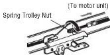
2 Tighten the Belt
- By hand, thread the spring trolley nut on the threaded shaft until it is finger trolley. Do not use any tools.
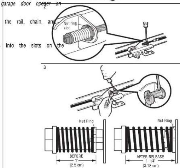
- Insert a flathead screwdriver tip into one of the nut ring slots and brace it trolley.
- Tighten the spring trolley nut with an adjustable wrench or a 7/16" open end quarter turn until the spring releases and snaps the nut ring against the trolle spring to optimum belt tension.
1
text_image
garage door opener on the rail, chain, and into the slots on the Nut ring slot Nut Ring BEFORE 1" (2.5 cm) AFTER RELEASE 1-1/4" (3.18 cm)Installation
IMPORTANT INSTALLATION INSTRUCTIONS
WARNING
To reduce the risk of SEVERE INJURY or DEATH:
- READ AND FOLLOW ALL INSTALLATION WARNINGS AND INSTRUCTIONS.
- Install garage door opener ONLY on properly balanced and lubricated garage door. An improperly balanced door may NOT reverse when required and could result in SEVERE INJURY or DEATH.
- ALL repairs to cables, spring assemblies and other hardware MUST be made by a door systems technician BEFORE installing opener. 10.
- Disable ALL locks and remove ALL ropes connected to garage door BEFORE installing opener to avoid entanglement. 11.
- Where possible, install the door opener 7 feet (2.13 m) or more above the floor.
- Mount the emergency release within reach, but at least 6 feet (1.83 m) above the and avoiding contact with vehicles to avoid accidental release.
- NEVER connect garage door opener to power source until instructed to do so.
-
NEVER wear watches, rings or loose clothing while installing or servicing opener. could be caught in garage door or opener mechanisms.
-
Install wall-mounted garage door control:
• within sight of the garage door. - out of reach of small children at a minimum height of 5 feet (1 above floors, landings, steps or any other adjacent walking surface.
away from ALL moving parts of the door. - Place entrapment warning label on wall next to garage door control in llling prominent location.
Place emergency release/safety reverse test label in plain view on inside garage door. - Upon completion of installation, test safety reversal system. Door reverse on contact with a 1-1/2" (3.8 cm) high object (or a 2x4 laid flat floor.
They To avoid SERIOUS PERSONAL INJURY or DEATH from electrocution, disconnect ALL electric power BEFORE performing ANY service or maintenance. -
DO NOT install on a one-piece door if using devices or features provided unattended close. Unattended devices and features are to be used ONLY sectional doors.
-
SAVE THESE INSTRUCTIONS.
Installation
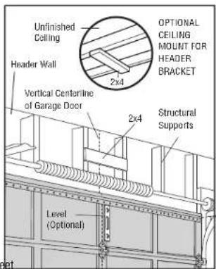
1 Determine the Header Bracket Location
WARNING
To prevent possible SERIOUS INJURY or DEATH:
- Header bracket MUST be RIGIDLY fastened to structural support on header wall or ceiling, otherwise garage door might NOT reverse when required. DO NOT install header bracket over drywall.
- Concrete anchors MUST be used if mounting header bracket or 2x4 into masonry.
- NEVER try to loosen, move or adjust garage door, springs, cables, pulleys, brackets, or their hardware. ALL of which are under EXTREME tension.
- ALWAYS call a trained door systems technician if garage door binds, sticks, or is out of balance. An unbalanced garage door might NOT reverse when required.
- DO NOT enable the Timer-to-Close functionality if operating either one-piece or swinging garage doors. To be enabled ONLY when operating a sectional door.
Close the door and mark the inside vertical centerline of the garage door.
Extend the line onto the header wall above the door. You can fasten the header bracket within 4 feet (1.22 m) of the left or right of the door center only if a torsion spring or center bearing plate is way; or you can attach it to the ceiling when clearance is minimal. (It may be mounted on the wall upside down if necessary, to gain approximately 1/2' (1 cm). If you need to install the header bracket on a 2x4 (on wall or ceiling), use lag screws (not provided) to securely fasten the 2x4 to structural supports.
Open your door to the highest point of travel as shown. Draw an intersecting horizontal line on the header wall 2' (5 cm) above the high point. This height will provide travel clearance for the top edge of the door.
NOTE: If the total number of inches exceeds the height available in your garage, use the maximum height possible, or refer to page 11 for ceiling installation.
text_image
Unfinished Ceiling Header Wall 2x4 OPTIONAL CEILING MOUNT FOR HEADER BRACKET Vertical Centerline of Garage Door 2x4 Structural Supports Level (Optional) set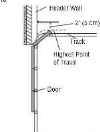
text_image
Header Wall 2" (5 cm) Track Highest Point of Travel DoorSectional door with curved track
Installation
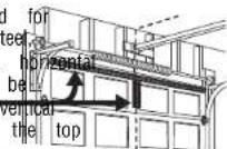
2 Install the Header Bracket
You can attach the header bracket either to the wall above the garage door, the instructions which will work best for your particular requirements. Do not install the header bracket over drywall. If installing into masonry, use concrete anchors (not p
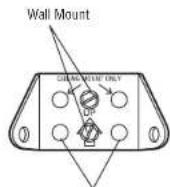
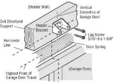
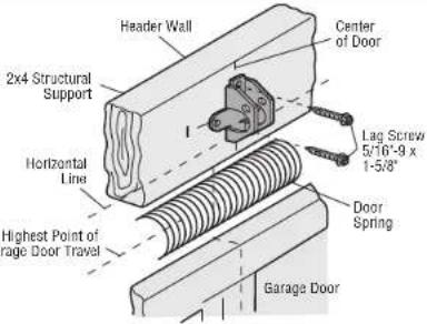
OPTION A - WALL INSTALLATION
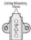
- Center the bracket on the vertical centerline with the bottom edge of the bracket on the horizontal line as shown (with the arrow pointing toward the ceiling).
- Mark the vertical set of bracket holes (do not use the holes designated for ceiling mount).
Drill 3/16 ^* pilot holes and fasten the bracket securely to a str
FOR T-RAIL
Optional Mounting Holes
text_image
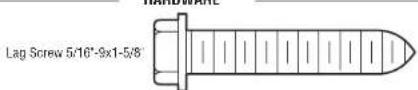
(Header Wall) 2x4 Structural Support Header Bracket Horizontal Line (Highest Point of Garage Door Travel) (Garage Door) Vertical Centerline of Garage Door Lag Screw 5/16-9 x 1-5/8" Door SpringFOR SQUARE RAIL
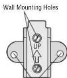
Optional
Mounting
Holes
text_image
Header Wall Center of Door 2x4 Structural Support Horizontal Line Lag Screw 5/16'-9 x 1-5/8" Highest Point of Surge Door Travel Door Spring Garage DoorOPTION B - CEILING INSTALLATION
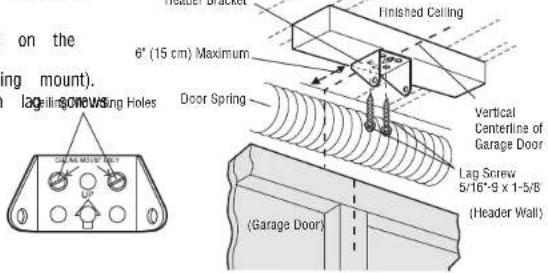
or to. Extend the vertical centerline onto the ceiling as shown.
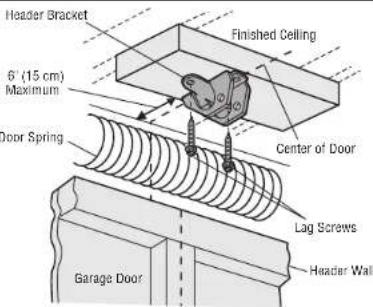
2. Center the bracket on the vertical mark, no more than 6" (15 cm) from the the arrow is pointing toward the wall. The bracket can be mounted flush again when clearance is minimal.
3. Mark the side holes. Drill 3/16" pilot holes and fasten bracket securely to a with the hardware provided.
FOR T-RAIL
text_image
on the wing mount). 6" (15 cm) Maximum Lag-lline 30W 2W 1W 1W 1W 1W Door Spring Finished Ceiling Vertical Centerline of Garage Door Lag Screw 5/16"-9 x 1-5/8" (Header Wall) (Garage Door)FOR SQUARE RAIL
text_image
Header Bracket 6" (15 cm) Maximum Door Spring Finished Ceiling Center of Door Lag Screws Garage Door Header WallInstallation
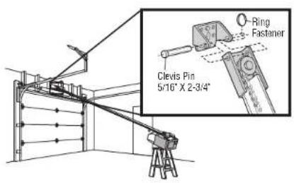
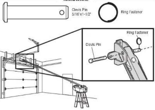
3 Attach the Rail to the Header Bracket
- Align the rail with the header bracket. Insert the clevis pin through the bracket and rail. Secure with the ring fastener.
NOTE: Use the packing material as a protective base for the garage door opener.
FOR T-RAIL
text_image
HARDWAREClevis Pin 5/16" x 2-3/4" Ring Fastener
text_image
Clevis Pin 5/16" X 2-3/4" Ring FastenerFOR SQUARE RAIL
holes in the header
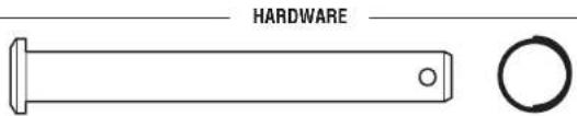
HARDWARE
text_image
Clevis Pin 5/16"x1-1/2" Ring Fastener Clevis Pin Ring FastenerInstallation
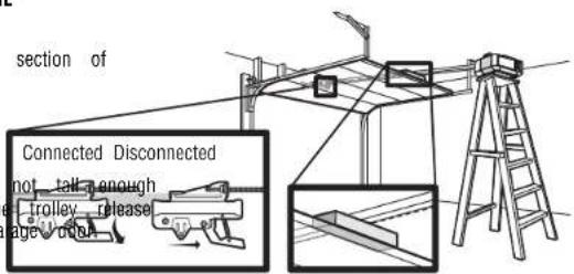
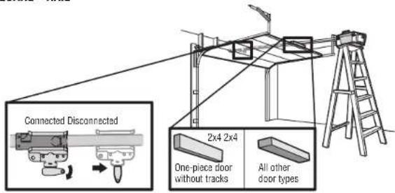
4 Position the Garage Door Opener
CAUTION
To prevent damage to garage door, rest garage door opener rail on 2x4 placed on top section of door.
- Remove the packing material and lift the garage door opener onto a ladder.
- Fully open the door and place a 2x4 (laid flat) under the rail.
A 2x4 is ideal for setting the distance between the rail and the door. If the ladder is you will need help at this point. If the door hits the trolley when it is raised, pull arm down to disconnect the inner and outer trolley. Slide the outer trolley toward the openener. The trolley can remain disconnected until instructed.
FOR T-RAIL
text_image
section of Connected Disconnected not tail enough trolley release page cutFOR SQUARE RAIL
text_image
Connected Disconnected 2x4 2x4 One-piece door without tracks All other door typesInstallation
5 Hang the Garage Door Opener
WARNING
To avoid possible SERIOUS INJURY from a falling garage door opener, fasten structural supports of the garage. Concrete anchors MUST be used if installing masonry.
Hanging your garage door opener will vary depending on your garage. Two representative installations are shown. Yours may be different. Hanging brackets should be angled (Figure 1) to provide rigid support. On finished ceilings (Figure 2), attach a sturdy metal bracket to structural supports before installing the opener. This bracket and fastening hardware are not provided.
-
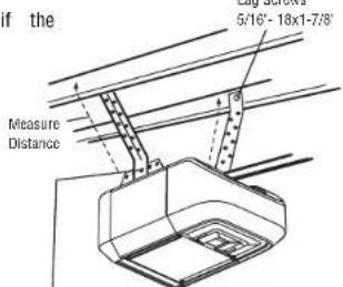
Measure the distance from each side of the motor unit to the structural support.
-
Cut both pieces of the hanging bracket to required lengths.
-
Drill 3/16' pilot holes in the structural supports.
-
Attach one end of each bracket to a support with 5/16"-18 x 1-7/8" lag screws (not
provided)
- Fasten the opener to the hanging brackets with 5/16'-18 x 7/8" hex bolts, lock washers and
nuts.
- Check to make sure the rail is centered over the door (or in line with the header bracket
bracket is not centered above the door).
- Remove the 2x4. Operate the door manually. If the door hits the rail, raise the header
bracket.
NOTE: DO NOT connect power to opener at this time.

HARDWARE

Hex Bolt 5/16"-18x7/6" Nut 5/16"-18 Lock Washer 5/16"
it SECURELY to ANY brackets into
FIGURE 1
Unfinished Ceiling
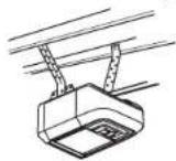
FIGURE 2
Finished Ceiling
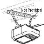
FIGURE 3
text_image
if the 5/16"- 18x1-7/8' Measure DistanceHex Bolt 5/16 - 18x7/8", Lock Washer 5/16", Nut 5/16" - 18
Installation
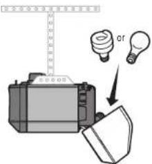
6 Install the Light Bulbs
CAUTION
To prevent possible OVERHEATING of the end panel or light socket:
• Use ONLY A19 light bulbs.
• DO NOT use incandescent bulbs larger than 100W.
• DO NOT use compact fluorescent light bulbs larger than 26W (100W
• DO NOT use halogen bulbs.
• DO NOT use short neck or specialty light bulbs.
LED bulbs may cause remote control radio interference. Use ONLY LED bulbs
here: chamberlain.com/bulb.
- Pull light lens down.
- Insert light bulb.
- Close light lens.
MODELS 81600 and 81602
text_image
Diagram showing a printer with a ruler and two lightbulb bulbs labeled Q1, illustrating a process or setup.MODELS 81550, 81640, and 81650 MODEL 83650-267
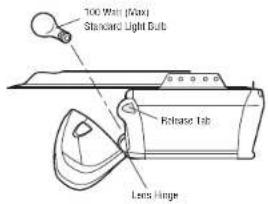
text_image
100 Waf (Max) Standard Light Bulb Release Strip Lens Hinge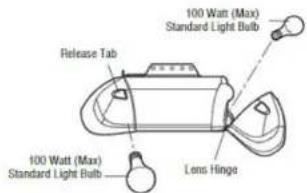
text_image
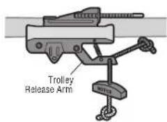
100 Watt (Max) Standard Light Bulb Release Tab 100 Watt (Max) Standard Light Bulb Lens Hinge7 Attach the Emergency Release Rope and Handle
WARNING
To prevent possible SERIOUS INJURY or DEATH from a falling garage door:
- If possible, use emergency release handle to disengage trolley ONLY when garage is CLOSED. Weak or broken springs or unbalanced door could result in an object falling rapidly and/or unexpectedly.
- NEVER use emergency release handle unless garage doorway is clear of persons obstructions.
recommendER use handle to pull door open or closed. If rope knot becomes untied, fall.
- Insert one end of the emergency release rope through the handle. Make sure is right side up. Secure with an overhand knot at least 1" (2.5 cm) from th to prevent slipping.
- Insert the other end of the emergency release rope through the hole in the arm. Mount the emergency release within reach, but at least 6 feet (1.83 m) a avoiding contact with vehicles to prevent accidental release and secure with an knot.
NOTE: If it is necessary to cut the emergency release rope, seal the cut end with a match or lighter to prevent unraveling. Ensure the emergency release rope and handle are above the top to avoid entanglement.
FOR T-RAIL
text_image
Trolley Release ArmInstallation
8 Install the Door Bracket
CAUTION
Fiberglass, aluminum or lightweight steel garage doors WILL REQUIRE reinforcement installation of door bracket. Contact the garage door manufacturer or installing reinforcement instructions or reinforcement kit. Failure to reinforce the top section according to the door manufacturer may void the door warranty.
A horizontal and vertical reinforcement is needed for lightweight garage doors (fiberglass, aluminum, steel doors with glass panel, etc.) (not provided). A floor reinforcement brace should be long enough to be secured to two or three vertical supports. A vertical reinforcement brace should cover the height of the panel. Contact the garage door manufacturer or installing dealer for opener reinforcement instructions or reinforcement kit.
NOTE: Many door reinforcement kits provide for direct attachment of the clevis pin and door arm. In this case you will not need the door bracket; proceed to the next step.
SECTIONAL DOORS
- Center the door bracket on the previously marked vertical centerline used for the bracket installation. Note correct UP placement, as stamped inside the bracket.
- Position the top edge of the bracket 2"-4" (5-10 cm) below the top edge of directly below any structural support across the top of the door.
- Mark, drill holes and install as follows, depending on your door's construction:
Metal or light weight doors using a vertical angle iron brace between the support and the door bracket:
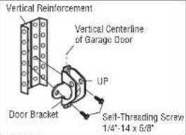
- Drill 3/16* fastening holes. Secure the door bracket using the two self threading (Figure 1)
• Alternately, use two 5/16"-18x2' bolts, lock washers and nuts (not provided). (Fig
Metal, insulated or light weight factory reinforced doors:
- Drill 3/16" fastening holes. Secure the door bracket using the self-threading screw (Figure 3)
Wood Doors:
t BEFOBSE top and bottom or side to side door bracket holes. Drill 5/16" holes thr ealer foandopeere bracket with 5/16'-18 x 2' carriage bolts, lock washers and nuts (as refigure 4)
NOTE: The 1/4"-14 x 5/8" self-threading screws are not intended for use on wood doors.
HARDWARE
Self-Threading Screw 1/4'-14 x 5/8'
FIGURE 1
text_image
Vertical Reinforcement Vertical Centerline of Garage Door UP Door Bracket Self-Threading Screw 1/4"-14 x 6/8"FIGURE 2
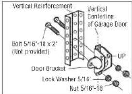
text_image
Vertical Reinforcement Bolt 5/16'-18 x 2" (Not provided) Vertical Centerline of Garage Door UP Door Bracket Lock Washer 5/16 Nut 5/16'-18FIGURE
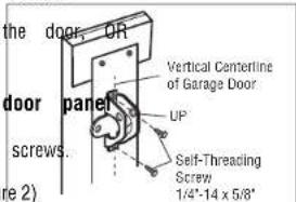
text_image
the door OR door panel screws. UP Vertical Centerline of Garage Door Self-Threading Screw 1/4"-14 x 5/8"FIGURE 4
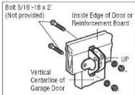
text_image
Bolt 5/16-18 x 2' (Not provided) Inside Edge of Door or Reinforcement Board Vertical Centerline of Garage Door UPInstallation
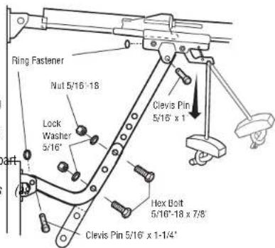
9 Connect the Door Arm to the Trolley
IMPORTANT: The groove on the straight door arm MUST face away from the curved door arm.
- T-Rail: Close the door. Disconnect the trolley by pulling the emergency release handle. Slide the outer trolley back (away from the door) about 2° (5 cm).
Square Rail: Close the door. Disconnect the trolley by pulling the emergency release handle. - Attach the straight door arm to the outer trolley using the clevis pin. Attach with the ring fastener.
- Attach the curved door arm to the door bracket using the clevis pin. Attach with the ring fastener.
- Align the straight door arm with the curved door arm. Select two aligned holes (as far as possible) and attach using the bolts, nuts and lock washers.
NOTE: If the holes do not line up, reverse the straight door arm. Select two aligned holes far apart as possible) and attach using the bolts, nuts and lock washers. - Pull the emergency release handle toward the garage door opener until the trolley release arm is horizontal. The trolley will re-engage automatically when the garage door opener is activated.
FOR T-RAIL
text_image
Ring Fastener Nut 5/16'-18 Lock Washer 5/16" Clevis Pin 5/16' x 1' Hex Bolt 5/16'-18 x 7/8" Clevis Pin 5/16' x 1-1/4'FOR SQUARE RAIL
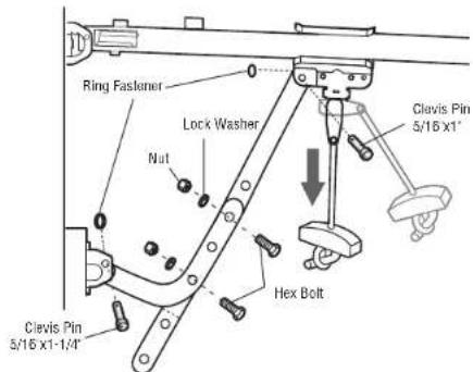
text_image
Ring Fastener Lock Washer Nut Clevis Pin 5/16 x1' Hex Bolt Clevis Pin 5/16 x1-1/4'Unattended Operation
The Timer-to-Close (TTC) feature, the myQ® App, and myQ® Garage Door and Gate examples of unattended close and are to be used ONLY with sectional doors. Any do that allows the door to close without being in the line of sight of the door is co close. The Timer-to-Close (TTC) feature, the myQ® App, and any other myQ® devices ONLY with sectional doors.
Install the Door Control
1 Install the Door Control - 882LMW
WARNING
To prevent possible SERIOUS INJURY or DEATH from electrocution:
- Be sure power is NOT connected BEFORE installing door control.
- Connect door control ONLY to 12 VOLT low voltage wires.
To prevent possible SERIOUS INJURY or DEATH from a closing garage door:
• Install door control within sight of garage door, out of reach of small minimum height of 5 feet (1.5 m) above floors, landings, steps or any walking surface, and away from ALL moving parts of door.
- NEVER permit children to operate or play with door control push butto control transmitters.
- Activate door ONLY when it can be seen clearly, is properly adjusted, obstructions to door travel.
• ALWAYS keep garage door in sight until completely closed. NEVER permit cross path of closing garage door.
INTRODUCTION
Compatible with My and Security+ 2.0 accessories, see page 45. Your garage door compatible with up to 2 Smart Control Panels or 4 of any other Security+ 2.0 NOTE: Older LiftMaster door controls and third party products are not compatible. Install door control within sight of garage door, out of reach of small children 5 feet (1.5 m) above floors, landings, steps or any other adjacent walking surface. ALL moving parts of door. For gang box installations it is not necessary to drywall anchors. Use the existing holes in the gang box.
NOTE: Your product may look different than the illustrations.
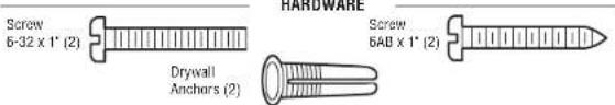
text_image
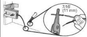
Screw 6-32 x 1" (2) Drywall Anchors (2) Screw 6AB x 1" (2)- Strip 7/16" (11 mm) of insulation from one end of the wire and separate th
- Connect one wire to each of the two screws on the back of the door cont be connected to either screw.
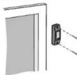
PRE-WIRED INSTALLATIONS: Choose any two wires to connect, note which wires a so the correct wires are connected at the garage door opener in a later step 3. Mark the location of the bottom mounting hole and drill a 5/32' hole.
-
Install the bottom screw, allowing 1/8" (3 mm) to protrude from the wall.
-
Position the bottom hole of the door control over the screw and slide down
- Lift the push bar up and mark the top hole.
children Remove the door control from the wall and drill a 5/32" hole for the top s her adjac position the bottom hole of the door control over the screw and slide down Attach the top screw.
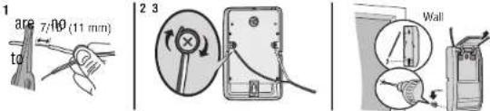
text_image
1 to ate 7/10 (11 mm) 2 3 Wall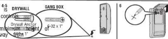
text_image
4-5 IS DRYWALL GANG BOX controls Drywall Anchor 6-32 x 1' 0" minimum height way from 1" 6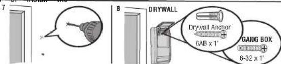
text_image
7 8 DRYWALL Drywall Anchor 6AB x 1" GANG BOX 6-32 x 1"Install the Door Control
1 Install the Door Control - 883LMW
WARNING
To prevent possible SERIOUS INJURY or DEATH from electrocution:
- Be sure power is NOT connected BEFORE installing door control.
- Connect door control ONLY to 12 VOLT low voltage wires.
To prevent possible SERIOUS INJURY or DEATH from a closing garage door:
- Install door control within sight of garage door, out of reach of small children at minimum height of 5 feet (1.5 m) above floors, landings, steps or any other adjacent walking surface, and away from ALL moving parts of door.
- NEVER permit children to operate or play with door control push buttons or remote
control transmitters.
- Activate door ONLY when it can be seen clearly, is properly adjusted, and there are no obstructions to door travel.
• ALWAYS keep garage door in sight until completely closed. NEVER permit anyone to cross path of closing garage door.
INTRODUCTION
Compatible with my and Security+ 2.0 accessories, see page 45. Your garage door opener is compatible with up to 2 Smart Control Panels or 4 of any other Security+ 2.0 door controls.
NOTE: Older LiftMaster door controls and third party products are not compatible.
Install door control within sight of garage door, out of reach of small children at a minimum height of
5 feet (1.5 m) above floors, landings, steps or any other adjacent walking surface, and away from
ALL moving parts of door. For gang box installations it is not necessary to drill holes or install the drywall anchors. Use the existing holes in the gang box.
NOTE: Your product may look different than the illustrations.
HARDWARE
-
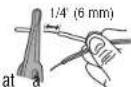
Strip 1/4" (6 mm) of insulation from one end of the wire and separate the
-
Connect one wire to each of the two screws on the back of the door cont be connected to either screw.
-
Mount the door control with the hardware provided.
23
Install the Door Control
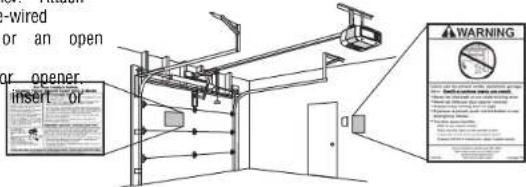
2 Wire the Door Control to the Garage Door Opener 3 Attach the Warning Labels
PRE-WIRED INSTALLATIONS: When wiring the door control to the garage door opener1, mAttachout the entrapment warning label on the wall near the door control with ta you use the same wires that are connected to the door control. 2. Attach the manual release/safety reverse test label in a visible location on the
- Run the white and red/white wire from the door control to the garage the wire to the wall and ceiling with staples (not applicable for gang installations). Do not pierce the wire with the staple as this may cause circuit.
- Strip 7/16" (11 mm) of insulation from the end of the wire near the
- Connect the wire to the red and white terminals on the garage door release wires from the terminal, push in the tab with screwdriver tip.
door openage Attach
box or pre-wired
a short or an open
garage doqr opener.
opener. To
text_image
wired or an open or opener insert or WARNING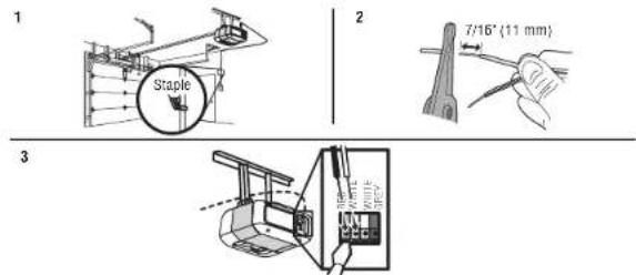
text_image
1 2 7/16" (11 mm) 3Install the Protector System®
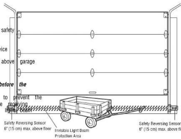
Introduction
WARNING
Be sure power is NOT connected to the garage door opener BEFORE installing the safety reversing sensor.
To prevent SERIOUS INJURY or DEATH from closing garage door:
- Correctly connect and align the safety reversing sensor. This required safety device MUST NOT be disabled.
• Install the safety reversing sensor so beam is NO HIGHER than 6" (15 cm) above floor.
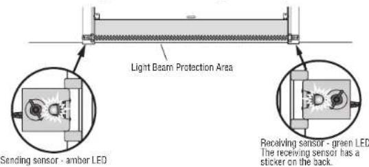
IMPORTANT: The safety reversing sensors MUST be connected and aligned correctly before garage door opener will move in the down direction.
The Protector System® includes two safety reversing sensors which use a light beam garage door from closing. The sending sensor (amber LED) transmits the beam to the sensor (green LED) when both are powered and aligned. If an obstruction breaks the while the door is closing, the door will stop, and reverse to the full open position.
When installing the safety reversing sensors, check:
- Sensors are installed INSIDE the garage.
- Sensor lenses are facing each other. IMPORTANT: Do not allow direct sunlight to the receiving sensor (green LED).
- Sensor beam is NO HIGHER than 6' (15 cm) above the floor and the light beam is unobstructed.
text_image
safety ice above garage before the to prevent the receiving light beam Safety Reversing Sensor 6" (15 cm) max. above floor Invisible Light Beam Protection Area safety Reversing Sensor 6" (15 cm) max. above floorInstall the Protector System®
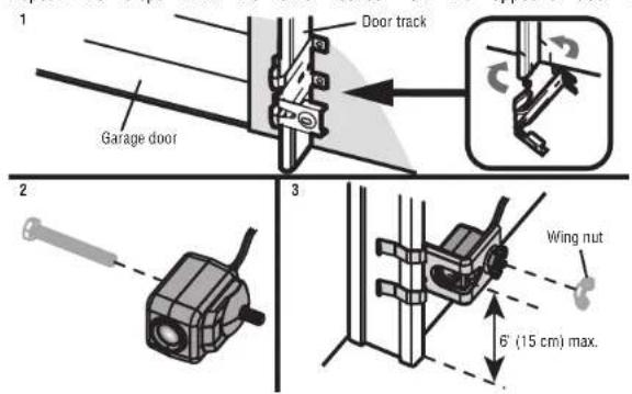
1 Install the Safety Reversing Sensors
The safety reversing sensors are designed to clip onto the door track with the brackets. If the door track will not support the sensor bracket a wall installation. The sensor beam should be NO HIGHER than 6" (15 cm) above the floor.
DOOR TRACK INSTALLATION
- Slide the curved arms of the sensor bracket around the edge of the place so that the sensor bracket is flush against the track.
- Slide the hex screw through the sensor.
- Attach the sensor to the bracket with the wing nut. Make sure the lens the bracket.
Repeat the steps with the other sensor on the opposite door track. Both lenses
text_image
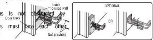
Door track Garage door Wing nut 6° (15 cm) max.WALL INSTALLATION
Make sure the brackets on each side are clear of the door track and have the same clearance so the sensors will align correctly. If additional clearance is needed, use ext 041A5281-1 (not provided) or wood blocks.
provided the sensor bracket against the wall with two lag screws (not provided). n is2. Recode-mented hex screw through the sensor.
- Attach the sensor to the bracket with the wing nut. Make sure the lens is the bracket.
Repeat the steps with the other sensor on the opposite side of the garage door. By face each other.
text_image
1 s is not door track s must face inside garage wall obstructed by each other Not preview OPTIONAL OR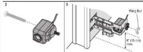
text_image
2 3 Wing Nut 6" (15 cm) max.Install the Protector System®
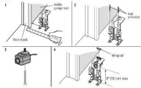
FLOOR INSTALLATION
- Measure the position of both sensor brackets so they will be the same and unobstructed.
- Attach the bracket to the floor with concrete anchors (not provided).
- Slide the hex screw through the sensor.
- Attach the sensor to the bracket with the wing nut. Make sure the len the bracket.
Repeat the steps with the other sensor on the opposite side of the garage door. face each other.
text_image
Inside garage wall Deor track 2 Foot provided 3 4 Wingnut 6" (15 cm) max2 Wire the Safety Reversing Sensors
PRE-WIRED INSTELLAYONS: If your garage already has wires installed for the safety r sensors, see page 25.
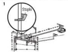
OPTION A - INSTALLATION WITHOUT PRE-WIRING
Run the wire from both sensors to the garage door opener. Attach with stapl puncture the wire.
or. Both Senarate the sensor wires and strip insulation from each end. Twist the two together. Then twist the two white/black wires together.
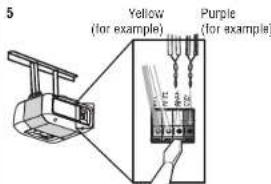
3. Using a screwdriver, push in the terminal tabs, and insert the white wires into terminal. Insert the white/black wires into the grey terminal.
text_image
1 Staple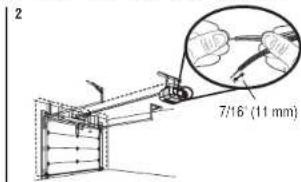
text_image
2 7/16' (11 mm)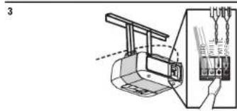
text_image
3Install the Protector System®
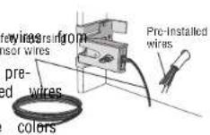
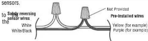
OPTION B - PRE-WIRED INSTALLATION
- Cut the sensor wires, making sure there is enough wire to reach the wall.
- Separate the sensor wires and strip insulation from each end. Choose two of the p installed wires and strip insulation from each end. Choose the same color pre-installed for each sensor.
- Connect the pre-installed wires to the sensor wires with wire nuts making sure the correspond for each sensor.
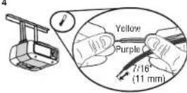
- At the garage door opener, strip the end of the wires previously connected to the Twist the like-colored wires together.
- Using a screwdriver, push in the terminal tabs, and insert the wire color connected sensor's white wire into the white terminal. Insert the other wire color connected to sensor's white/black wire into the grey terminal.
1
2
the sensors.
text_image
sensors. to the Safety reversing sensor wires White White/Black Not Provided Pre-installed wires Yellow (for example) Purple (for example)4
5
text_image
5 Yellow (for example) Purple (for example)To insert or remove the wires from the terminal, push in the tab with a screwdriver tip.
Power
1 Connect Power

WARNING
To prevent possible SERIOUS INJURY or DEATH from electrocution or fire:
- Be sure power is NOT connected to the opener, and disconnect power removing cover to establish permanent wiring connection.
- Garage door installation and wiring MUST be in compliance with ALL building codes.
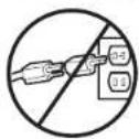
- NEVER use an extension cord, 2-wire adapter, or change plug in ANY outlet. Be sure the opener is grounded.
To avoid installation difficulties, do not activate the garage door opener at the To reduce the risk of electric shock, your garage door opener has a grounding grounding pin. This plug will only fit into a grounding type outlet. If the plug outlet, contact a qualified electrician to install the proper outlet.
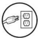
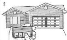
THERE ARE TWO OPTIONS FOR CONNECTING POWER:
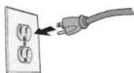
OPTION A - TYPICAL WIRING
-
Plug in the garage door opener into a grounded outlet.
-
DO NOT run garage door opener at this time.
TYPICAL WIRING
to circuit BEFORE
local electrical and
way to make it fit
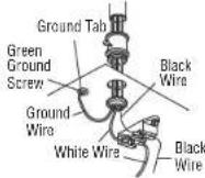
OPTION B - PERMANENT WIRING
If permanent wiring is required by your local code, refer to the following procedure's time. The plug with a third type: "permanent connection through the 7/8" hole in the top of the motor unit (according code): "I don't fit into your
-
Remove the motor unit cover screws and set the cover aside.
-
Remove the attached 3-prong cord.
-
Connect the black (line) wire to the screw on the brass terminal; the white the screw on the silver terminal; and the ground wire to the green ground s opener must be grounded.
-
Reinstall the cover.
PERMANENT WIRING
Power
2 Align the Safety Reversing Sensors
IMPORTANT: The safety reversing sensors MUST be connected and aligned corre garage door opener will move in the down direction.
When the garage door opener has power, check the safety reversing sensors. If aligned and wired correctly, both LEDs will glow steadily.
text_image
Light Beam Protection Area Sending sensor - amber LED Receiving sensor - green LED The receiving sensor has a sticker on the back.To align the safety reversing sensors:
-
Loosen the wing nuts.
-
Adjust the sensors up or down until both LEDs glow steady indicating
-
Tighten the wing nut to secure the sensor.
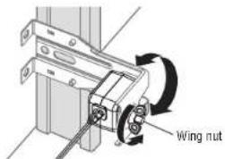
text_image
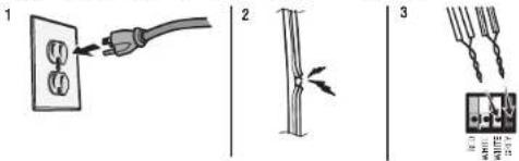
Wing nutSAFETY SENSOR TROUBLESHOOTING
If either of the sensor LEDs are off, there is no power to the sensor:
- Check that you have power to the garage door opener. the2. Check the sensor wire is not shorted or broken.
text_image
Diagram showing three-step electrical installation procedure: wire connection, cable termination, and terminal wiring connections.If the green receiving sensor LED is blinking, the sensors are obstructed or misalign
-
Check for obstructions in the sensor light beam.
-
Align the sensors.
-
If the receiving sensor (green LED) faces direct sunlight, switch the receiving s the sending sensor and repeat 1 Install the Safety Reversing Sensors page 23 proper operation.
alignment.
Power
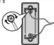
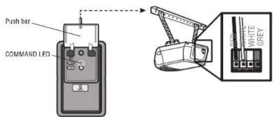
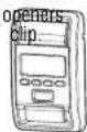
3 Ensure the Door Control is Wired Correctly
Models: 81550, 81600, 81602, 81650, 83650-267
If the door control has been installed and wired correctly, the command LED behind the push bar will blink.
text_image
Push bar COMMAND LED DIP WHITE WHITE GREYModel: 81640
If the door control has been installed and wired correctly, the LED behind the push button will blink (883LMW).
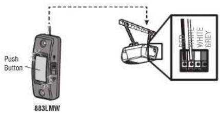
text_image
Push Button 883LMW Black WHITE GREYAdjustments
Introduction
WARNING
Without a properly installed safety reversal system, persons (particularly small children) could be SERIOUSLY INJURED or KILLED by a closing garage door.
- Incorrect adjustment of garage door travel limits will interfere with proper operation of safety reversal system.
• After ANY adjustments are made, the safety reversal system MUST be tested. Door MUST reverse on contact with 1-1/2" (3.8 cm) high object (or 2x4 laid flat) on floor.
CAUTION
To prevent damage to vehicles, be sure fully open door provides adequate clearance.
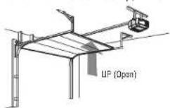
Your garage door opener is designed with electronic controls to make setup and adjustments easy. While programming the travel, the UP and DOWN buttons can be used to move the door as needed. During the Automatic Force Setup, the door will automatically open and close.
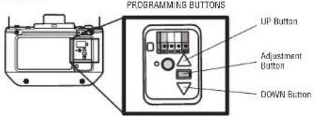
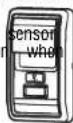
PROGRAMMING BUTTONS
The programming buttons are located on the left or back side panel of the garage door opener and are used to program the travel. While programming, the UP and DOWN buttons can be used to move the door as needed.
text_image
PROGRAMMING BUTTONS UP Button Adjustment Button DOWN ButtonAdjustments
1 - Program the Travel
WARNING
Without a properly installed safety reversal system, persons (particularly small class SERIOUSLY INJURED or KILLED by a closing garage door.
- Incorrect adjustment of garage door travel limits will interfere with proper safety reversal system.
• After ANY adjustments are made, the safety reversal system MUST be t MUST reverse on contact with 1-1/2" (3.8 cm) high object (or 2x4 laid
Note: While programming the travel, the UP and DOWN buttons can be used needed. During the Automatic Force Setup, the door will automatically open and
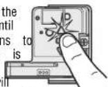
1 Press and hold the
Adjustment Button until
the UP Button begins
flash and/or a beep is
heard. The Safety
Reversing Sensors
be disconnected during
process.
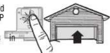
2 Press and
hold the UP
Button until
the door is
the desired
UP position.
Travel
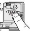
3 Once the door is in
desired UP position pr
and release the
Adjustment Button. The
garage door opener fig
will flash twice and t
DOWN Button will beg
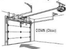
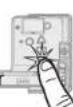
4 Press and
hold the
DOWN button
until the doc
is in the
desired DOWN
5 Once the door is in
desired DOWN position
press and release the
Adjustment Button. The
garage door opener
will flash twice. Program
the Travel is now complete. If the garage door
opener lights flash 5 times, then programming
has timed out and the Travel Limits have not
been set. Please restart the Program the Travel
process.
2 - Automatic Force Set Up
Once both the up and down positions have been manually set, the Safety Reversing reconnect and become operational. Then, the opener will enter a force-sensing operation automatically moving the door open and close. The garage door opener will sound an open panel could be before automatically opening and closing the door. The garage door opener three times, confirming that the Automatic Force Setup completed successfully. Adjustment of operation of complete.
sted. Door that you hear one long beep after the door attempts to move, then the Automatic For completed successfully. Please start over at step 1 of Program the Travel.
o move the door as
close.
NOTE: If the travel/force setup process is not completed successfully any attempt to activate the opener from a remote/keyless entry or wall control will not work and the opener will lights 2 times.
Adjustments
3 - Test the Safety Reversal System
WARNING
Without a properly installed safety reversal system, persons (particularly small) be SERIOUSLY INJURED or KILLED by a closing garage door.
• Safety reversal system MUST be tested every month.
- After ANY adjustments are made, the safety reversal system MUST be MUST reverse on contact with 1-1/2" (3.8 cm) high object (or 2x4 floor.
1 With the door fully open, place a 1-1/2 inch (3.8 cm) board (or a 2x4 centered under the garage door.
2 Press the remote control push button to close the door. The door MUST contact with the board.
If the door stops but does not reverse:
- Repeat Program the Travel (see Adjustment Step 1):
- Repeat the Safety Reversal test.
If the test continues to fail, call a trained door systems technician.
4 - Test the Protector ®System
WARNING
children) could Without a properly installed safety reversing sensor, persons (particularly small children) could be SERIOUSLY INJURED or KILLED by a closing garage door.
tested. Door
laid 1flatOpen table door. Place an obstruction in the path of the door.
2 Press the remote control push button to close the door. The door will not move inch (2.5 cm).
The garage door opener will not close from a remote control if the LED in either sensor is off (alerting you to the fact that the sensor is misaligned or obstructed). If the garage door opener closes the door when the safety reversing sensor is obst sensors are no more than 6 inches [15 cm] above the floor), call for a trained technician.
Battery Backup
1 Install the Battery\*
Model: 81602
WARNING
To reduce the risk of FIRE or INJURY to persons:
- Disconnect ALL electric and battery power BEFORE performing ANY service maintenance.
• Use ONLY LiftMaster part # 485LM for replacement battery.
- DO NOT dispose of battery in fire. Battery may explode. Check with disposal instructions.
CAUTION
ALWAYS wear protective gloves and eye protection when changing the battery the battery compartment.
- Unplug the garage door opener.
- Open the light lens of the garage door opener. Use a Phillips head screwdriver to remove the battery cover on the garage door opener.
- Partially insert the battery into the battery compartment with the terminals facing out.
- Connect red (+) and black (-) wires from the garage door opener to the corresponding
terminals on the battery. - Replace the battery cover.
- Plug in the garage door opener.
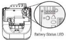
- Wait for the green Battery Status LED to start flashing before proceeding to test the battery.

Battery
Status LED
2 Test the Battery
- Unplug the garage door opener. The battery status LED will either glow solid indicating opener is operating on battery power or will flash indicating low batt. NOTE: Make sure the garage door opener is unplugged.
- Open and close the door using the remote control or door control. NOTE: The garage door opener may run slower if the battery is not fully charged. The battery will ta fully charge.
- Plug in the garage door opener. Verify the battery status LED is flashing green, battery is charging.
* If applicable.
Battery Backup
3 Charge the Battery
The battery charges when the garage door opener is plugged into a 120Vac
power and requires 24 hours to fully charge. A fully charged battery supplies
door opener for up to 24 hours of normal operation during an electrical po
electrical power has been restored, the battery will recharge within 24 hours.
approximately 1 to 2 years with normal usage. To obtain maximum battery li
disconnect the battery when the garage door opener is unplugged for an ext
such as a summer or winter home.
4 Battery Status LED
eGREEN oLED: that has
12Vdcsystemthe angaragermal.
outageA Solid green LED light indicates the battery is fully charged.
e battery flashing green LED indicates the battery is being charged
ORANGEveled: damage,
eThe pegedgeof doime, opener has lost power and is in battery backup mode.
- A solid orange LED with beep, sounding approximately every 2 seconds, indicate garage door opener is operating on battery power.
- A flashing orange LED with beep, sounding every 30 seconds, indicates the bat
RED LED:
The battery needs to be replaced.
- A solid red LED with beep, sounding every 30 seconds, indicates the battery 'hold a charge. Go to LiftMaster.com to purchase a replacement battery to allow to operate during a power outage.
NOTE: The Battery Status LED is most visible with the garage door opener light off. Battery does not
have to be fully charged to operate the garage door opener.
Operation
IMPORTANT SAFETY INSTRUCTIONS
WARNING
To reduce the risk of SEVERE INJURY or DEATH:
- READ AND FOLLOW ALL WARNINGS AND INSTRUCTIONS.
- ALWAYS keep remote controls out of reach of children. NEVER permit children contact with 1-1/2" (3.8 cm) high object (or a 2x4 laid flat) on the floor. Failur or play with garage door control push buttons or remote controls. the garage door opener properly increases the risk of SEVERE INJURY or DEAT
- ONLY activate garage door when it can be seen clearly, it is properly adjusted ALWAYS the EEP GARAGE DOOR PROPERLY BALANCED (see page 4). An improper are no obstructions to door travel. balanced door may NOT reverse when required and could result in SEVERE INJ
- ALWAYS keep garage door in sight and away from people and objects until completely closed. NO ONE SHOULD CROSS THE PATH OF THE MOVING DOOR. 12. ALL repairs to cables, spring assemblies and other hardware. ALL of which are
- NO ONE SHOULD GO UNDER A STOPPED, PARTIALLY OPENED DOOR.
- If possible, use emergency release handle to disengage trolley ONLY when garage to avoid interference with the proper operation of the garage door opener when CLOSED. Use caution when using this release with the door open. Weak or broken in the garage, unplug garage door opener before operating welder springs or unbalanced door could result in an open door falling rapidly and/or To avoid SERIOUS PERSONAL INJURY or DEATH from electrocution, disconnect A unexpectedly and increasing the risk of SEVERE INJURY or DEATH. EXTREME tension, MUST be made by a trained door systems technician.
- NEVER use emergency release handle unless garage doorway is clear of persons. The operator system is equipped with an unattended operation feature. The door obstructions. move unexpectedly. NO ONE SHOULD CROSS THE PATH OF THE MOVING DOOR
-
NEVER use handle to pull garage door open or closed. If rope knot becomes DontiDT you stall on a one-piece door if using devices or features providing unacould fall. close. Unattended devices and features are to be used ONLY with sectional doo
-
After ANY adjustments are made, the safety reversal system MUST be tested.
- SAVE THESE INSTRUCTIONS.
Operation
Features
Your garage door opener is equipped with features to provide you with greater garage door operation.
ALERT2CLOSE
The Alert2Close feature provides a visual and an audible alert that an unattende
TIMER-TO-CLOSE (TTC)
The TTC feature automatically closes the door after a specified time period that a TTC enabled door control (Models 881LMW or 880LMW). Prior to and during garage door opener lights will flash and the garage door opener will beep.
MYQ
myQ® technology uses a 900MHz signal to provide two-way communication between door opener and ®reabled accessories. Your garage door opener is compatible with myQ® accessories.
SECURITY+ 2.0 REMOTE CONTROLS AND DOOR CONTROLS
Your garage door opener has already been programmed at the factory to opera control, which changes with each use, randomly accessing over 100 billion new with myQand Security+ 2.0 accessories, see page 45
NOTE: Older LiftMaster remote controls, door controls, and third party products are not compatible.
| Security+ 2.0Accessories | MEMORY CAPACITY |
| Remote Controls Up | to 12 |
| Door Controls Up | to 2 Smart Control Panels or 4 of any other Security+ 2. controls |
| Keyless Entries Up | to 1 |
THE PROTECTOR SYSTEM SAFETY REVERSING SENSORS)
When properly connected and aligned, the safety reversing sensors will detect an obstruction in the path of the infrared beam. If an obstruction breaks the infrared beam while the door is closing, the door will stop and reverse to full open position. If the door is fully open, and the safety reversing sensors are not installed, or are misaligned, the door will not close from a remote control. However, you can close the door if you hold the button on the door control or keyless entry until the door is fully closed. The safety reversing sensors do not effect the opening cycle.
LIGHTS
The garage door opener light bulbs will turn on when the opener is initially plugged restored after interruption, or when the garage door opener is activated. The lights wi automatically after 4-1/2 minutes. Use an incandescent A19 light bulb (100 watt maxim
USING YOUR GARAGE DOOR OPENER
The garage closing opener can be activated through a wall-mounted door control, remote wireless keyless entry or my App.
When the adjusted is solved and the garage door opener is activated the door will operate, makes door contact with the obstruction while opening, the door will stop, opener beeps and times. When the door is in any position other than closed and the garage door operate, the door will close. If the garage door makes contact with an obstruction while close reverse, opener beeps and lights flash 5 times. However, you can close the door if button or gate the door control or keyless entry until the door is fully closed.
The up safety reversing sensors do not affect the opening cycle. The safety reversing ser connected and aligned correctly before the garage door opener will move in the down
BATTERY BACKUP\*
The with battery status system allows access in and out of your garage, even when the other. The voltage door opener is operating on battery power, the garage door opener the light will not function, the Battery Status LED will glow solid orange, and a bee approximately every 2 seconds. *if applicable
door
Operation
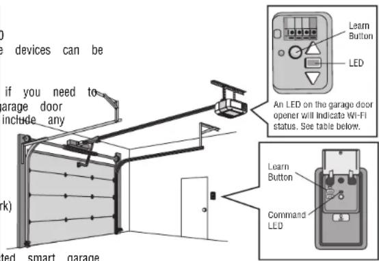
Connect With Your Smartphone
The Wi-Fi Garage Door Opener is compatible with® enabled accessories. Up to 10 devices can be paired to the Wi-Fi garage door opener's internal gateway. These controlled with the ®. These devices include any combination and empty or openers, Wi-Fi garage door openers, Lighting Controls, MyGate operators or myQ commercial door operators. A LiftMaster Internet Gateway (828LM) can be added control more than 10 devices using®. The byQ to 6 devices can be paired to gate opener itself (controlled by garage door opener through 900MHz). These devices in combination of MyLight controls or a garage door and gate monitor.
YOU WILL NEED:
• Wi-Fi enabled smartphone, tablet or laptop
- Broadband Internet Connection
• Wi-Fi signal in the garage (2.4 GHz, 802.11b/g/n required), see page 4
- Password for your home network (router's main account, not guest network)
- myQ ^ serial number located on the garage door opener
DOWNLOAD THE myQ® APP TO SET UP AN ACCOUNT AND CONNECT
Open and close your door, get alerts and set schedules from anywhere. Connected smart garage door openers also receive software updates to ensure the opener has the latest operational features.
The garage door opener must run through a complete cycle before it will activate programming.
- Download the myQ® App.
- Set up an account and connect.
text_image
devices can be if you need to garage door include any k) ted smart garage Learn Button LED An LED on the garage door opener will indicate Wi-Fi status. See table below. Learn Button Command LEDWIFI STATUS
| LED Definition | |
| Blue | Off - Wi-Fi is not turned on.Blinking - Garage door opener is in Wi-Fi learn mode.Solid - Mobile device connected to the garage door open |
| Blue and Green | Blinking - Attempting to connect to router. |
| Green | Blinking - Attempting to connect to the Internet server.Solid - Wi-Fi has been set up and garage door opener internet. |
NOTES:
myQ App control WILL NOT work if the garage door opener is operating on battery. To erase the Wi-Fi settings, see page 41.
Operation
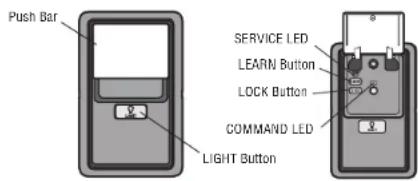
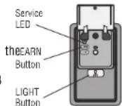
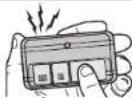
Using the Multi-Function Door Control 882LMW
SYNCHRONIZE THE DOOR CONTROL
To synchronize the door control to the garage door opener, press the push door opener activates (it may take up to 3 presses). Test the door control each press of the push bar will activate the garage door opener.
text_image
Push Bar SERVICE LED LEARN Button LOCK Button COMMAND LED LIGHT ButtonPUSH BAR
Press the push bar to open or close the door.
LIGHT BUTTON
Press the LIGHT button to turn the garage door opener lights on or off. When the lights are turned on they will stay on until the LIGHT button is pressed again, or until the garage door opener is activated. Once the garage door opener is activated the lights will turn off after the specified period of time (the factory setting is 4-1/2 minutes). The LIGHT button will not control the lights when the door is in motion.
The following features are accessible by lifting up the push bar:
LEARN A DEVICE
Any compatible remote controls, wireless keyless accessoriesQ can be programmed to until the aggregator opener by pressing the LEARN button of the door control, see BLOCK pressing the push bar,
The LOCK feature is designed to prevent activation of the garage door opener from while still allowing activation from the door control and keyless entry. This feature is peace of mind when the home is empty (i.e. vacation).
MAINTENANCE ALERT (MAS)
This feature assists the homeowner in ensuring the garage door opener system stays working condition. When the garage door opener needs to be serviced (approximately 4 door opener cycles) the command (yellow) and service (red) LEDs will begin to altern and forth. The factory setting for the MAS feature is off and can be activated at t Contact your installing dealer for service.
Operation
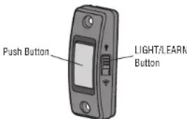
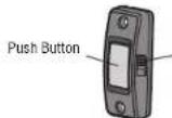
Using the Push Button Door Control 883LMW
SYNCHRONIZE THE DOOR CONTROL
To synchronize the door control to the garage door opener, press the push door opener activates (it may take up to 3 presses). Test the door control button, each press of the push button will activate the garage door opener.
button until the garage by pressing the push
text_image
Push Button LIGHT/LEARN ButtonPUSH BUTTON
Press the push button to open or close the door.
LIGHT/LEARN BUTTON
Press the LIGHT button to turn the garage door opener lights on or off. When the lights are turned on they will stay on until the LIGHT button is pressed again, or until the garage door opener is activated. Once the garage door opener is activated the lights will turn off after the specified period of time (the factory setting is 4-1/2 minutes). The LIGHT button will not control the lights when the door is in motion.
Operation
Using the Door Control
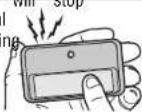
LOCK
Your remote controls will NOT work when LOCK mode is active however your keyless entry will still allow access to your garage.
Activate:
Press and hold the LOCK button for 2 seconds. The command LED will flash as long as the lock feature is activated and your handheld remote control will not operate your door at this time. Deactivate:
Press and hold the LOCK button again for 2 seconds. The command LED will stop flashing and normal operation will resume.
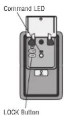
MAINTENANCE ALERT SYSTEM (MAS): Activate/Deactivate:
Press and hold the LEARN button. Then press LIGHT button. The service LED will flash the status; Active is 2 flashes and deactivated is 3 flashes.
Operation
Remote Control
Your remote control has been programmed at the factory to operate with you opener.
Older LiftMaster remote controls are NOT compatible, see page 45 for compatible Programming can be done through the door control or the learn button the game program additional accessories refer to the instructions provided with the accessor LiftMaster.com. If your vehicle is equipped with ^® , a homelink require an external dependency on the make, model, and year of your vehicle. Visit www.homelink.com information.
TO ADD, REPROGRAM, OR CHANGE A REMOTE CONTROL/KEYLESS ENTRY THE PUSH BUTTON DOOR CONTROL - MODEL 882LMW
- Press the LEARN button on the door control twice. The Command LED
- Remote Control:
Press the button on the remote control that you wish to operate your Keyless Entry:
Enter a 4-digit personal identification number (PIN) of your choice on the keypad. Then press the ENTER button.
The garage door opener lights will flash (or two clicks will be heard) and the blinking when the code has been programmed. Repeat the steps above for pro-remote controls or keyless entry devices. If programming is unsuccessful, program the learn button.
1
2
DR
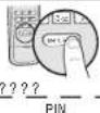
TO ADD, REPROGRAM, OR CHANGE A REMOTE CONTROL/KEYLESS ENTRY PIN THE MULTI FUNCTION DOOR CONTROL - MODEL 883LMW
- Press and hold the LIGHT button and the push button until the push button
accessor blink.
- Remote Control:
Page door opener. To y or visit press the button on the remote control that you wish to operate your garage danter Keyless Entry:
Enter a 4-digit personal identification number (PIN) of your choice on the keyle keypad. Then press the ENTER button.
The garage door opener lights will flash (or two clicks will be heard) when the co-programmied. Repeat the steps above for programming additional remote controls or key devices. If programming is unsuccessful, program the remote using the learn button.
will blink.
(二)
garage door.
(二) 本次股东大会的召集和召开程序
keyless entry
(二) 2017年1月1日
Command LED will stop
ramming additional
the remote usin
the remote use
LIGHT/LEARN Button
OR

???? PIN
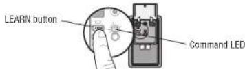
TO ADD, REPROGRAM, OR CHANGE A REMOTE CONTROL USING THE LEARN
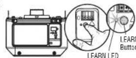
- Press and release the LEARN Button on the garage door opener.
- Press and hold the button on the remote control that you wish to use. Rele when the garage door opener lights blink or two clicks are heard.
Operation
To Erase the Memory
ERASE ALL REMOTE CONTROLS AND KEYLESS ENTRIES
- Press and hold the LEARN button on garage door opener until the learn (approximately 6 seconds). All remote control and keyless entry codes are Reprogram any accessory you wish to use.
ERASE ALL DEVICES INCLUDING® ENABLED ACCESSORIES
- Press and hold the LEARN button on garage door opener until the learn (approximately 6 seconds).
- Immediately press and hold the LEARN button again until the learn LED are now erased. Reprogram any accessory you wish to use.
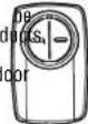
ERASE THE Wi-Fi® NETWORK FROM THE GARAGE DOOR OPENER
- Press and hold the black adjustment button on the garage door opener heard (Approximately 6 seconds).
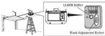
text_image
LEARN Button Black Adjustment ButtonTo Open the Door Manually
LED goes out
WARNING
now erased. To prevent possible SERIOUS INJURY or DEATH from a falling garage door:
- If possible, use emergency release handle to disengage trolley ONLY when garage is CLOSED. Weak or broken springs or unbalanced door could result in an open LED falling rapidly and/or unexpectedly.
• NEVER use emergency release handle unless garage doorway is clear of persons
goes • obstructions NEVER use handle to pull door open or closed. If rope knot becomes untied,
until 3_ beeps are
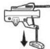
FOR T-RAIL
Disconnect the trolley
- The door should be fully closed if possible.
- Pull down on the emergency release handle.
Reconnect the trolley
The lockout feature prevents the trolley from reconnecting automatically.
- Pull the emergency release handle down and back (toward the opener). The door can then be raised and lowered manually as often as necessary.
- To disengage the lockout feature, pull the handle straight down. The trolley will reconnect on the next UP or DOWN operation, either manually or by using the door control or remote control.
Maintenance
Maintenance Schedule
EVERY MONTH
- Manually operate door. If it is unbalanced or binding, call a trained door
- Check to be sure door opens and closes fully. Adjust if necessary, see
- Test the safety reversal system. Adjust if necessary, see page 31.
EVERY YEAR
- Oil door rollers, bearings and hinges. The garage door opener does not lubrication. Do not grease the door tracks.
- Test the battery and consider replacing the battery to ensure the garage operate during an electrical power outage, see page 32 to test the batte
EVERY TWO TO THREE YEARS - T-RAIL ONLY
- Use a rag to wipe away the existing grease from the garage door layer of white lithium grease to the top and underside of the rail slides.
NOTICE: This device complies with part 15 of the FCC rules and innovation, Science and Economic Development Canada license-exempt RSSs. Operation is subject to the following two conditions: (1) this device may not cause harmful interference, and (2) this device must accept any interference received, including interference that may cause undesired operation.
Any changes or modifications not expressly approved by the party responsible for compliance could void the user's authority to operate the equipment.
This device must be installed to ensure a minimum 20 cm (8 in.) distance is maintained between users/systanders and devices. This device has been tested and turned to comply with the limits for a Class B digital device, pursuant to part 15 of the FCC rules and Industry Canada ICS standards. These limits are designed to provide reasonable protection against harmful interference in a residential installation. This equipment generates, uses and can radiate radio frequency energy and, if not installed and used in accordance with the instructions, may cause harmful interference to radio communications. However, there is no guarantees that interference will not occur in a particular installation. If this equipment does cause harmful interference to radio or television reception, which can be determined by turning the equipment off and on, the user is encouraged to try to correct the interference by one or more of the following measures:
- Roorient or relocate the receiving antenna.
- Increase the separation between the equipment and receiver.
- Connect the equipment into an outlet on a circuit different from that to which the receiver is connected.
- Consult the dealer or an experienced radio/TV technician for help.
The Remote Control Battery
systems technician.
WARNING
page 30 10 prevent possible SERIOUS INJURY or DEATH:
• NEVER allow small children near batteries.
- If battery is swallowed, immediately notify doctor.
requirereadditionak of fire, explosion or chemical burn:
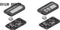
- Replace ONLY with 3V CR2032 coin batteries.
door • opener Noill recharge, disassemble, heat above 212°F (100°C) or incinerate. backup.
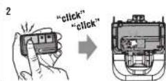
To replace the battery, pry open the case in the middle, then at each side with the rail. Reapply a small visit of clin. Insert replacement battery
where the rolley replacement battery positive side up (+). Replace the batteries with only 3V CR2032 coin cell batteries.
Dispose of old batteries properly.
Troubleshooting
Diagnostic Chart
Your garage door opener is programmed with self-diagnostic capabilities. The UP and DOWN arrows on the garage door opener flash the diagnostic codes.
| Up | DIAGNOSTIC CODE SYMPTOM SOLUTION | ||||
| Arrow | Flash(es) | Down | Arrow | Flash(es) | |
| 1 | 1 | The garage door opener will not close. | |||
| 1 | 2 | The garage door opener will not close. | |||
| 1 | 3 | The door control will not function. | |||
| 1 | 4 | The garage door opener will not close. | |||
| 1 | 5 | Door moves 6-8" (15-20 cm) stops or reverses. | |||
| No movement, only a single click. | |||||
| Opener hums for 1-2 seconds no movement. | |||||
| 1 | 6 | Door coasts after it has come to a complete stop. | |||
| 2 | 1-5 | No movement, or sound. | |||
| 3 | 2 | Unable to set the travel or retain position. | |||
| 3 | 3 | The battery status LED is constantly flashing green.* | |||
Troubleshooting
| DIAGNOSTIC CODE SYMPTOM SOLUTION | |||||
| Up | Arrow | Flash(es) | Down | Arrow | Flash(es) |
| 4 | 1-4 | Door is moving, stops or reverses. Opener beeps and lights flash. | Manually open and close the door. Check for binding or obstructions, such as a brok door lock, correct as needed. If the door is binding or sticking, contact a trained dc technician. If door is not binding or sticking attempt to reprogram travel (refer to page). | ||
| 4 | 5 | Opener runs approximately 6-8" (15-20 cm), stops and reverses. | Communication error to travel module. Check travel module connections, replace travel min necessary. | ||
| 4 | 6 | The garage door opener will not close. | Safety reversing sensors are misaligned or were momentarily obstructed. Realign both sensors to ensure both LEDs are steady and not flickering. Make sure nothing is hanging or mo door that would interrupt the sensor's path while closing. | ||
The garage door opener will NOT enter ARWi-Finode:
• After the initial installation of the garage door opener, the garage door complete a full cycle (open and closed) before the Wi-Fi LEARN mode
- If there has been a recent power outage, the garage door opener must before the Wi-Fi LEARN mode can be activated.
See page 36 to activate Wi-Fi LEARN mode.
Cannot connect garage door opener to home Wi-Fi network:
- Ensure the mySerial number was entered correctly and try again characters myQ are between A-F and 0-9 only.
- Weak Wi-Fi signal in the garage. Ensure the Wi-Fi signal is reaching the garage, see page 4 or visit LiftMaster.com/Customer-Support for more information.
My door will not close:
The safety reversing sensor must be connected and aligned correctly before the garage door opener will move in the down direction.
- Check for binding or obstructions anywhere along the track to garage floor.
- The safety reversing sensor must be connected and aligned correctly before the garage door opener will move in the down direction.
- Verify the safety reversing sensors are properly installed, aligned and free of any obstructions.
My neighbor's remote control opens my garage door:
ofence thest memory from your garage door opener and reprogram the remote control(s) cMy b vehicleated HomePink is not programming to my garage door opener:
Depending a on full the cycle make, model, and year of your vehicle an external adapter may b www.homelink.com for additional information.
Accessories
878MAX 877MGX

MAX Wireless Keyless Entry:
For use outside of the home to the garage using a 4-digit ALL LiftMaster openers from 1
893MAX 3-Button MAX Remote Control:

Compatible with LiftMaster garage door manufactured since 1993. Includes visor
880LMW Smart Control Panel:
Displays temperature, time and system diagnostics; includes a push bar to open and close the door and a lock feature for extra security. Security+ 2.0 and Wi-Fi compatible.
819LMB myQ
® Home Bridge:
compatibility to your door opener. Use check the status
891LM Single
Button Remote Control:
Compatible with LiftMaster garage door manufactured since 1993. Includes visor
882LMW Multi-Function Control Panel:

Security+ 2.0 and Wi-Fi compatible.
Apple is a trademark of Apple Inc. registered in the U.S. and other countries. HomeXt is a trademark of Apple Inc.
485LM 12V Battery for Backup System:

Provides backup power to the garage opener.
374UT Mini Universal Remote Control:

The Mini Universal Remote Control can programmed to activate up to two products such as a garage door openight myQ controls, gate operator, or commercial do operator.
380UT Universal Remote Control:
The Universal Remote Control can be programmed to activate up to two products, s as a garage door opener, gate operator, or commercial door operator.
881LMW Motion Detecting Control Panel with Timer-to-886LMW Motion Detecting Control Panel:

Close Control:
Multi-function door control with motion that automatically turns opener lights detects a person entering the garage. Security+2.0 and Wi-Fi compatible.
it
Multi-function door control with motion sensor that automatically turns opener lights on when it detects a person entering the garage. Security+ 2.0 and Wi-Fi compatible.
Warranty
| WARRANTY PERIOD | |||||||||
| Models | Parts | Motor | Accessories | Belt | Battery | Backup* | |||
| 81600 | 1 year 4 years 1 year N/A N/A | ||||||||
| 81650 | |||||||||
| 81640 | |||||||||
| 81602 | 1 year | 4 years | 1 year | N/A | 1 year | ||||
| 81550 | 1 year | 4 years | 1 year | 10 years | $ N/A | ||||
| 83650-267 | 1 year | Lifetime | 1 year | N/A | N/A | ||||
The proper operation of this product is dependent on your compliance with the instructions regarding installation, operation, and maintenance and testing. Failure to comply strictly with those instructions will void this limited warranty in its entirety.
If, during the limited warranty period, this product appears to contain a defect covered by this limited warranty, call 1-800-528-9131, toll free, before dismantling this product. You will be advised of disassembly and shipping instructions when you call. Then send the product or component, pre-paid and insured, as directed to our service center for warranty repair. Please include a brief description of the problem and a dated proof-of-purchase receipt with any product returned for warranty repair. Products returned to Seller for warranty repair, which upon receipt by Seller are confirmed to be defective and covered by this limited warranty, will be repaired or replaced (at Seller's sole option) at no cost to you and returned pre-paid. Defective parts will be repaired or replaced with new or factory-rebuilt parts at Seller's sole option. [You are responsible for any costs incurred in removing and/or reinstalling the product or any component].
ALL IMPLIED WARRANTIES FOR THE PRODUCT, INCLUDING BUT NOT LIMITED TO ANY IMPLIED WARRANTIES OF MERCHANTABILITY AND FITNESS FOR A PARTICULAR PURPOSE, ARE LIMITED IN DURATION TO THE APPLICABLE LIMITED WARRANTY PERIOD SET FORTH ABOVE FOR THE RELATED COMPONENT(S), AND NO IMPLIED WARRANTIES WILL EXIST OR APPLY AFTER SUCH PERIOD. Some States and Provinces do not allow limitations on how long an implied warranty lasts, so the above limitation may not apply to you. THIS LIMITED WARRANTY DOES NOT COVER NON-DEFECT DAMAGE, DAMAGE CAUSED BY IMPROPER INSTALLATION, OPERATION OR CARE (INCLUDING, BUT NOT LIMITED TO ABUSE, MISUSE, FAILURE TO PROVIDE REASONABLE AND NECESSARY MAINTENANCE, UNAUTHORIZED REPAIRS OR ANY ALTERATIONS TO THIS PRODUCT), LABOR CHARGES FOR REINSTALLING A REPAIRED OR REPLACED UNIT, REPLACEMENT OF CONSUMABLE ITEMS (E.G., BATTERIES IN REMOTE CONTROL TRANSMITTERS AND LIGHT BULBS), OR UNITS INSTALLED FOR NON-RESIDENTIAL USE. THIS LIMITED WARRANTY DOES NOT COVER ANY PROBLEMS WITH, OR RELATING TO, THE GARAGE DOOR OR GARAGE DOOR HARDWARE, INCLUDING BUT NOT LIMITED TO THE DOOR SPRINGS, DOOR ROLLERS, DOOR ALIGNMENT OR HINGES. THIS LIMITED WARRANTY ALSO DOES NOT COVER ANY PROBLEMS CAUSED BY INTERFERENCE. UNDER NO CIRCUMSTANCES SHALL SELLER BE LIABLE FOR CONSEQUENTIAL, INCIDENTAL OR SPECIAL DAMAGES ARISING IN CONNECTION WITH USE, OR INABILITY TO USE, THIS PRODUCT. IN NO EVENT SHALL SELLER'S LIABILITY FOR BREACH OF WARRANTY, BREACH OF CONTRACT, NEGLIGENCE OR STRICT LIABILITY EXCEED THE COST OF THE PRODUCT COVERED HEREBY. NO PERSON IS AUTHORIZED TO ASSUME FOR US ANY OTHER LIABILITY IN CONNECTION WITH THE SALE OF THIS PRODUCT.
Some states and provinces do not allow the exclusion or limitation of consequential, incidental or special damages, so the above limitation or exclusion may not apply to you. This limited warranty gives you specific legal rights, and you may also have other rights, which vary from state to state and province to province.
*If applicable
Automatic Garage Door Opener Safety & Maintenance Guide
Garage Door Opener Safety - An Automatic Decision
A garage door is the largest moving object in the home. An improperly adjusted garage door and opener can exert deadly force when the door closes – which could lead to entrapment of children or adults and subsequent injury or death.
Proper installation, operation, maintenance, and testing of the garage door and automatic opener are necessary to provide a safe, trouble-free system. Careless operation or allowing children to play with or use garage door opener controls are also dangerous situations that can lead to tragic results. A few simple precautions can protect your family and friends from potential harm. Please review the safety and maintenance tips in this guide carefully and keep it for reference. Check the operation of your garage door and opener to ensure they function in a safe and trouble-free manner. Be sure to read all Important Safety Information found in your garage door opener's manual as it provides more details and safety considerations than can be supplied with this guide.
Garage Door Openers are Not Toys
Discuss garage door and opener safety with your children. Explain the danger of being trapped under the door.
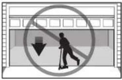
text_image
Prohibition sign showing a person using a scooter with a downward arrow, enclosed in a building outlineStay away from a moving door. The wall-mounted push button should be
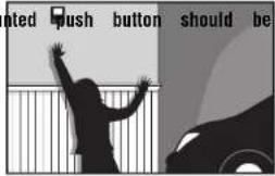
text_image
oted push button should beout of reach of
children, at least 5 feet from the nearest standing surfa and away from all moving parts. Mount and use the where you can clearly see the closing garage door.
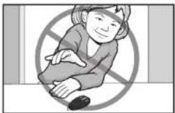
natural_image
Illustration of a person sitting with arms crossed, enclosed in a prohibition symbol (no text or symbols present)Keep transmitters and remote controls out of reach of children. Do not let children play with or use transmitters or other remote control devices.
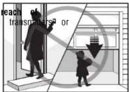
text_image
reach of transmitters orKeep the door in sight until it completely closes when using the wall-mounted push button or transmitter.
Routine Maintenance Can Prevent Tragedies
Make monthly inspection and testing of your garage door and opener system a part of your regular routine. Review your owner's manual for both the door and door opener. If you don't have the owner's manuals, contact the manufacturer(s) and request a copy for your specific model(s). Look for the opener model number on the back of the power unit.

WARNING - SPRINGS ARE UNDER HIGH TENSION. ONLY QUALIFIED INDIVIDUALS SHOULD ADJUST THEM.
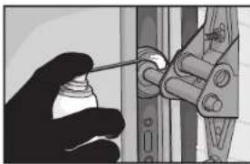
natural_image
Close-up of a hand using a spray gun to adjust or install a mechanical component (no visible text or symbols)Visually check the door and installation:
- Starting with the door in the closed position, use the manual disconnect on the opener to disconnect the door.
- Look for signs of wear or damage on hinges, rollers, springs, and door panels.
• These parts may require periodic lubrication. Check the owner's manual for suggested maintenance.
• If any signs of damage are evident, contact a trained door systems technician for assistance. - Verify the photoeye height is no higher than 6' from the garage floor
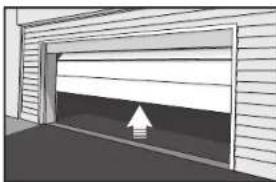
natural_image
Exterior view of a modern garage with a white arrow indicating a loading or clearance point (no text or symbols)Test the door for proper operation:
- Open and close the door manually using handles or suitable gripping points.
• The door should move freely and without difficulty.
• The door should balance and stay partially open 3–4 feet above the floor.
• If you detect any signs of improper operation, contact a trained door systems technician for assistance.
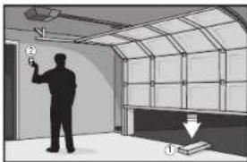
natural_image
Interior view of a room with a person holding a wall-mounted device and a window, showing structural details (no text or symbols visible)Test the opener safety features:
- Reconnect the opener to the door using the manual disconnect and open the door.
- Place a 2x4 board flat in the path of the door (1) and try to close it (2). The
contact with the 2x4 and then reverse direction.
• Block the photoelectric sensor by waving an object in front of the sensor and attempt to
door should not close unless the wall-mounted push button is manually held during operation.
• If the opener does not perform as described, contact a trained door systems technician for assistance.

stop when it comes in
the door The Door & Access Systems
Manufacturers Association
Repair Parts
Models 81600, 81602, 81640, 81650, and 83650-267
For Square Rail see instructions included with the LMSSRKIT.
RAIL ASSEMBLY PARTS
| Description Part Number | |
| 1 Chain - for 7 foot door | 041D3484 |
| Chain - for 8 foot door | 041D3483 |
| Chain - for 10 foot door | 041D3485 |
| 2 Chain Pulley Bracket | 041A4813 |
| 3 Master link | 004A1008 |
| 4 One-Piece Rail 7 feet (2.1 m) | 1707LM |
| One-Piece Rail 8 feet (2.4 m) | 1708LM |
| One-Piece Rail 10 feet (3 m) | 1710LM |
| 5 Trolley Assembly Includes: Threaded Shaft (1), Nuts (2), Washer (1), Clevis Pin (1), Ring (1), Master Link (1), Chain Extension | 041A3489 |
| 6 Trolley Threaded Shaft | 041A6689 |
| Not Shown | |
| Rail Grease | K083A0011-1 |
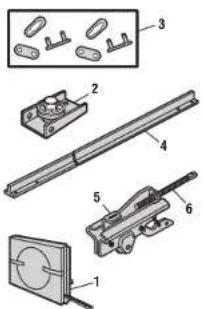
text_image
Technical diagram of a mechanical assembly with numbered components, including parts labeled 1 through 6.ACCESSORIES
| Description Part Number | ||
| 1 | Push Button Door Control Model 81640 | 883LMW |
| 2 | Multi-function Control Panel Models 81600, 81602, 81650, and 83650-267 | 882LMW |
| 3 | 1 Button Remote Control Model 81640 | 891LM |
| 4 | 3 Button Remote Control Models 81600, 81602, 81650, and 83650-267 | 893LM |
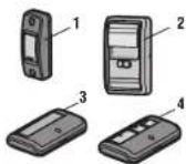
INSTALLATION PARTS
| Description Part Number | |
| 1 Curved door arm | 041B0035B |
| 2 Door bracket with clevis pin and fastener | 041A8047 |
| 3 Emergency release rope and handle | 041A2828 |
| 4 Header bracket with clevis pin and fastener | 041A4353 |
| 5 Remote control visor clip | K029B0137 |
| 6 Safety sensor bracket | 041-0155-000 |
| 7 Safety sensor kit with receiving and sending sensors with 3 feet (.9 m) 2-conductor wire | 041-0136 |
| 8 Straight door arm | 4178B0034B |
| 9 White and red/white wire | 041B4494-1 |
| 10 3V CR2032 lithium battery | K010A0020 |
| 11 Extension bracket (optional) | 041A5281-1 |
| Not Shown | |
| Installation hardware bag | 041A2770-6 |
| User's Guide | 114-5711-010 |
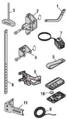
text_image
Exploded view diagram of mechanical components with numbered parts for identificationRepair Parts
Models 81600 and 81602
GARAGE DOOR OPENER PARTS
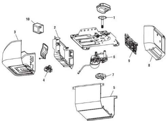
text_image
Exploded view diagram of a device with numbered parts for identification| Description Part Number | |
| 1 Sprocket and sprocket cover | 041B5348-2 |
| 2 End panel with light socket | |
| Model 81600 | 041A7756-1 |
| Model 81602 | 041A7618 |
| 3 Light Lens | 041A7562 |
| 4 Light socket | 041C0279 |
| 5 Cover | 041-0133-000 |
| 6 Motor with travel module | 041D8006-1 |
| 7 Travel Module | 041D8071-4 |
| 8 Logic board end panel | 041D0233-3 |
| 9 Logic board | 050DCTBMC |
| 10 Battery Backup (Model 81602 only) | 485LM |
| Not Shown | |
| Wire Hamess | 041D9069 |
| Transformer | |
| Model 81600 | 041A7635-1 |
| Model 81602 | 041D0277-1 |
| Line cord | 041B4245-1 |
| Terminal block | 041A3150 |
Repair Parts
Models 81640 and 81650
GARAGE DOOR OPENER PARTS
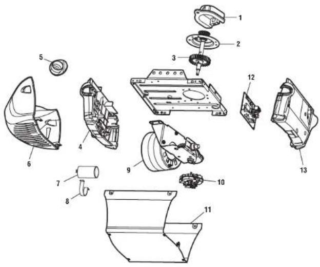
text_image
Exploded view diagram of a mechanical assembly with numbered parts for identification| Description Part Number | ||
| 1 | Sprocket cover | 031D0380M |
| 2 | Gear and sprocket | 041C4220A |
| 3 | Drive and Worm Gear | 041A2817 |
| 4 | Front end panel with all labels | 041A8393 |
| 5 | Light socket | 041C0279 |
| 6 | Light lens | K108D0079M |
| 7 | Capacitor | 030B0532-1 |
| 8 | Capacitor bracket | K012A0373 |
| 9 | Universal motor | 041D7440 |
| 10 | Travel module | 041D7742-7 |
| 11 | Cover | 041D9018 |
| 12 | Logic board | 050ACTBMC |
| 13 | Logic board end panel | 041D0239-1 |
| Not Shown | ||
| Line cord | 041B4245-1 | |
| Terminal block | 041A3150 | |
| Wire Harness | 041A7946 | |
Repair Parts
Model 83650-267
For Square Rail see instructions included with the rail kit model LMSSRKIT.
GARAGE DOOR OPENER PARTS
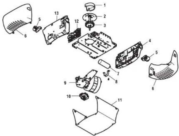
text_image
Exploded view diagram of a mechanical assembly with numbered parts for identification| Description Part Number | ||
| 1 | Sprocket cover with screws | 031D0380M |
| 2 | Gear and sprocket | 041C4220A |
| 3 | Drive and Worm Gear | 041A2817 |
| 4 | Front end panel with all labels | 041A8393 |
| 5 | Light socket | 041C0279 |
| 6 | Light lens | K108D0079M |
| 7 | Capacitor | 030B0532-1 |
| 8 | Capacitor bracket | K012A0373 |
| 9 | Universal motor | 041D7440 |
| 10 | Travel module | 041D7742-7 |
| 11 | Cover | 041D8993 |
| 12 | Logic board | 050ACTBMC |
| 13 | Logic board end panel | 041D0210-1 |
| Not Shown | ||
| Line cord | 041B4245-1 | |
| Wire Harness | 041D8227 | |
| Terminal block | 041A3150 |
Repair Parts
Model 81550
RAIL ASSEMBLY PARTS
| Description | Part | Number | ||
| 1 | Belt - for 7 foot door | 041A5434-11A | ||
| Belt - for 8 foot door | 041A5434-13A | |||
| Belt - for 10 foot door | 041A5434-14A | |||
| 2 | Belt Pulley Bracket | 041B5424 | ||
| 3 | Master link | 004A1008 | ||
| 4 | One-Piece Rail 7 feet (2.1 m) | 2777BD | ||
| One-Piece Rail 8 feet (2.4 m) | 2778BD | |||
| One-Piece Rail 10 feet (3 m) | 2770BD | |||
| 5 | Trolley Assembly Includes: Master Link 1B3869-3A(2), Clevis Pin (1), Ring (1), Belt Clip (1),Threaded Shaft (1), andTensioner Assembly (1) | |||
| 6 | Tensioner Assembly | 041B4103 | ||
| 7 | Trolley Threaded Shaft | 041A6689 | ||
ACCESSORIES
| Description | Part Number | ||
| 1 | Multi-function | control panel | 882LMW |
| 2 | 3-button | remote control | 893LM |
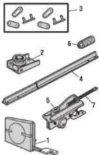
text_image
Exploded view diagram of a mechanical assembly with numbered parts for identification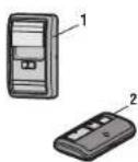
INSTALLATION PARTS
| Description Part Number | |
| 1 Curved door arm | 041B0035B |
| 2 Door bracket with clevis pin and 041A5647-1 | |
| 3 Emergency release rope and handle 041A2828 | |
| 4 Header bracket with clevis pin and 041A4353-1 fastener | |
| 5 Remote control visor clip | K029B0137 |
| 6 Safety sensor bracket | 041-0155-000 |
| 7 Safety sensor kit with receiving and 041-0136 sending sensors with 3 feet (.9 m) 2-conductor wire | |
| 8 Straight door arm | 4178B0034B |
| 9 White and red/white wire | 041B4494-1 |
| 10 3V CR2032 lithium battery | K010A0020 |
| 11 Extension bracket (optional) | 041A5281-1 |
| Not Shown | |
| Installation hardware bag | 041A2770-6 |
| User's Guide | 114-5711-010 |
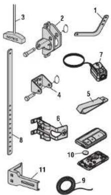
text_image
Exploded view diagram of mechanical components with numbered parts for identificationRepair Parts
Model 81550
GARAGE DOOR OPENER PARTS

text_image
Exploded view diagram of a mechanical assembly with numbered parts for identification| Description Part Number | ||
| 1 | Sprocket cover | 041A4371 |
| 2 | Gear and sprocket | 041A4885-4 |
| 3 | Drive and Worm Gear | 041A2817 |
| 4 | Front end panel with all labels | 041A8393 |
| 5 | Light socket | 041C0279 |
| 6 | Light lens | K108D0079M |
| 7 | Capacitor | 030B0532-1 |
| 8 | Capacitor bracket | K012A0373 |
| 9 | Universal motor | 041D7440 |
| 10 | Travel module | 041D7742-7 |
| 11 | Cover | 041D9018 |
| 12 | Logic board | 050ACTBMC |
| 13 | Logic Board End Panel | 041D0239-1 |
| 14 | Line cord | 041B4245-1 |
| Not Shown | ||
| Wire Harness | 041A7946 | |
| Terminal block | 041A3150 | |
CONTACT INFORMATION:
Use your part number, part name or model number to find you need.
For parts, go to:
LiftMaster.com/parts
For help and troubleshooting, go to:
support.chamberlaingroup.com
the infc
Wi-Fi ^05 is a registered trademark of Wi-Fi Alliance.
App Store is a service mark of Apple Inc. Google Play is a trademark of Google Inc.
© 2022. LiftMaster
All Rights Reserved
natural_image
Exterior view of a LiftMaster robotic device (no text or symbols visible on body)text_image
Diagram illustrating smart home connectivity with a smartphone displaying WiFi icons and a person using a device.text_image
Illustration of various hand tools and accessories with labeled parts and ratiosPréparation
B. Poulie et support
C. Support de porte
B. Poulie et support
C. Support de porte
natural_image
Illustration of a hand using a tool to connect wires, with an inset showing a magnified view of the cable (no text or symbols present)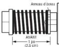
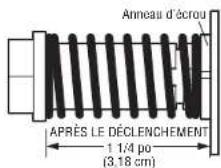
INSTRUCTIONS D'INSTALLATION IMPORTANTES
! ⚠️ AVERTISSEMENT
text_image
POUR LE RAIL EN T Incarbation du jour Support 250mm 2nd Support 150mm Ligre N° antaise Support 150mm Pout de montage optionnels Mant du l'breau Support 150mm 2nd Support 150mm 2nd Support 150mm 2nd Support 150mm 2nd Support 150mm 2nd Support 150mm 2nd Support 150mm 2nd Support 150mm 2nd Support 150mm 2nd Support 150mm 2nd Support 150mm 2n Support 150mm 2n Support 150mm 2n Support 150mm 2n Support 150mm 2n Support 150mm 2n Support 150mm 2n Support 150mm 2n Support 150mm 2n Support 150mm 2n Support 150mm 2m Support 150mm 2m Support 150mm 2m Support 150mm 2m Support 150mm 2m Support 150mm 2m Support 150mm 2m Support 150mm 2m Support 150mm 2m Support 150mm 2m Support 150mm 2n Support 150mm 2n Support 150mm 2n Support 150mm 2n Support 150mm 2n Support 150mm 2n Support 150mm 2n Support 150mm 2n Support 150mm 2n Support 150mm 2k Support 150mm 2k Support 150mm 2k Support 150mm 2k Support 150mm 2k Support 150mm 2k Support 150mm 2k Support 150mm 2k Support 150mm 2k Support 150mm 2kOPTION B - INSTALLATION AU PLAFOND
text_image
Diagram showing a printer with a ruler and two lightbulb bulbs labeled 'or', illustrating the process of printing or discharging.MODÈLES 81550, 81640, and 81650 MODÈLE 83650-267
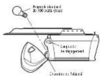
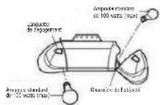
text_image
Diagram showing three-step electrical installation steps: plug, wire connection, and terminal wiring with disassembled cable.text_image
Dodge DOITtext_image
Diagram showing three steps of electrical installation: wire connection, home renovation, and socket installation.Batterie de secours
Activer/Désactiver :
text_image
1 2 " Clic " " Clic "Fonctionnement
text_image
Safety warning sign with pictogram of a person using a scooter and a 'no stop' symbolnatural_image
Illustration of a person sitting with a crossed-out hand symbol (no text or symbols present)natural_image
Illustration of a hand using a spray gun to clean or store items (no text or symbols visible)natural_image
Exterior view of a modern garage with a white upward arrow on the door (no text or symbols)natural_image
Interior view of a room with a person holding a wall-mounted device and a window, no visible text or symbolsManufacturers Association
International
Pièces détachées
text_image
Technical diagram of a mechanical assembly with numbered components, including parts labeled 1 through 6.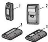
PIÈCES D'INSTALLATION
text_image
Exploded view diagram of mechanical parts with numbered labels for identificationPièces détachées
text_image
Exploded view diagram of a device with numbered parts for identificationtext_image
Exploded view diagram of a mechanical assembly with numbered parts for identificationFor Square Rail see instructions included with the rail kit model LMSSRKIT.
GARAGE DOOR OPENER PARTS
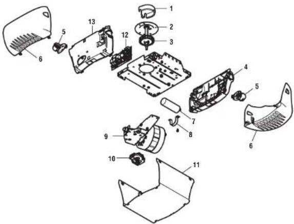
text_image
Exploded view diagram of a car body with numbered parts for identification| Description Part Number | ||
| 1 | Sprocket cover with screws | 031D0380M |
| 2 | Engrenage et pignon | 041C4220A |
| 3 | Drive and Worm Gear | 041A2817 |
| 4 | Front end panel with all labels | 041A8393 |
| 5 | Douille | 041C0279 |
| 6 | Lentille de lampe | K108D0079M |
| 7 | Condensateur | 030B0532-1 |
| 8 | Support du condensateur | K012A0373 |
| 9 | Universal motor | 041D7440 |
| 10 | Module de déplacement | 041D7742-7 |
| 11 | Cover | 041D8993 |
| 12 | Logic board | 050ACTB |
| 13 | Logic board end panel | 041D0210-1 |
| Not Shown | ||
| Câble de ligne | 041B4245-1 | |
| Wire Harness | 041D8227 | |
| Bornier | 041A3150 | |
COORDONNÉES DE CONTACT :
text_image
Exploded view diagram of a mechanical assembly with numbered parts for identification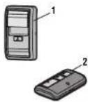
PIÈCES D'INSTALLATION
text_image
Exploded view diagram of mechanical parts with numbered labels for identificationPièces détachées
Modèle 81550
PIÈCES DÉTACHÉES DE L'OUVRE-PORTE DE GARAGE

text_image
Exploded view diagram of a mechanical assembly with numbered parts for identificationLiftMaster.com/parts
natural_image
Exterior view of a liftmaster robotic device (no visible text or symbols on body)Available on most iOS and Android Devices
LiftMaster
300 Windsor Drive
Oak Brook, IL 60523
LiftMaster®
Tabla de contenidos
text_image
Illustration showing a smartphone connected to a smart grid with Wi-Fi icons, accompanied by a person holding a flag.WiFiHelp.LiftMaster.com.
text_image
Illustration of various hand tools and accessories with labeled parts and ratiosPreparación
Inventario en la caja: modelos 81600, 81602, 81640, 83650-267
natural_image
Illustration of a hand using a tool to adjust or install a mechanical component, with an inset showing a magnified view of the component (no text or symbols present)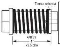

Instalación
text_image
Diagram showing a device with a light bulb and an arrow pointing to it, labeled 'or' indicating a component or operation.MODELOS 81550, 81640 y 81650 MODELO 83650-267
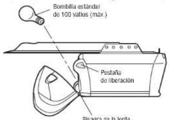
text_image
Diagram illustrating three-step cable installation procedure: wire connection, cable extension, and cable tip assembly.text_image
Diagram showing a hand holding a payment terminal and a close-up of a PIN with a dial, illustrating the mechanism of payment or PIN usage.PARA AÑADIR, REPROGRAMAR O CAMBIAR UN CONTROL REMOTO UTILIZANDO BOTÓN LEARN
text_image
Safety warning sign with pictogram of a person using an e-scooter and no stop signnatural_image
Illustration of a person sitting with arms crossed, enclosed in a prohibition symbol (no text or symbols present)natural_image
Illustration of a hand using a spray gun to adjust or install a mechanical component (no text or symbols visible)natural_image
Exterior view of a modern garage with a white upward arrow on the door (no text or symbols)natural_image
Interior view of a room with a person holding a wall-mounted device and a window, no visible text or symbolstext_image
Technical diagram of a mechanical assembly with numbered components, including parts labeled 1 through 6.ACCESORIOS
text_image
Exploded view diagram of mechanical components with numbered parts for identificationPiezas de repuesto
text_image
Exploded view diagram of a device with numbered parts for identificationtext_image
Exploded view diagram of a mechanical assembly with numbered parts for identificationFor Square Rail see instructions included with the rail kit model LMSSRKIT.
GARAGE DOOR OPENER PARTS

text_image
Exploded view diagram of a car's internal components with numbered parts for identification| Description Part Number | ||
| 1 | Sprocket cover with screws | 031D0380M |
| 2 | Engranaje y piñón | 041C4220A |
| 3 | Drive and Worm Gear | 041A2817 |
| 4 | Front end panel with all labels | 041A8393 |
| 5 | Portalámparas | 041C0279 |
| 6 | Lente de luz | K108D0079M |
| 7 | Condensador | 030B0532-1 |
| 8 | Soporte del condensador | K012A0373 |
| 9 | Universal motor | 041D7440 |
| 10 | Módulo de recorrido | 041D7742-7 |
| 11 | Cover | 041D8993 |
| 12 | Logic board | 050ACTB |
| 13 | Logic board end panel | 041D0210-1 |
| Not Shown | ||
| Cable de alimentación | 041B4245-1 | |
| Wire Harness | 041D8227 | |
| Bloque del terminal | 041A3150 | |
text_image
Exploded view diagram of a mechanical assembly with numbered parts for identification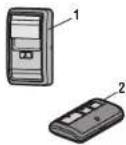
text_image
Exploded view diagram of mechanical parts with numbered labels for identificationPiezas de repuesto
Modelo 81550
PIEZAS DEL ABREPUERTAS DE GARAJE