84504R - Garage door LIFT-MASTER - Free user manual and instructions
Find the device manual for free 84504R LIFT-MASTER in PDF.

| Product Type | Belt-driven garage door opener with integrated camera |
| Model | 84504R |
| Brand | LIFT-MASTER |
| Power Supply | 120 V, 60 Hz, ground wire |
| Drive Type | Reinforced rubber belt |
| Rail Dimensions | 2.1 m (7 ft), 2.4 m (8 ft) or 3 m (10 ft) depending on version |
| Weight (estimated) | Approximately 15 kg (motor + rail) |
| Sound Level | Reduced noise level thanks to belt drive |
| Connectivity | Wi-Fi 2.4 GHz (802.11 b/g/n), myQ® app |
| Integrated Camera | Yes, with live view and alerts |
| Backup Battery | Rechargeable 12V battery (model 485LM), up to 24 hours backup |
| Lighting | Built-in LEDs, turn on upon activation, 4.5 min timer |
| Number of remote controls included | 2 |
| Number of compatible wall controls | Up to 2 Smart Control Panels or 4 other Security+ 2.0 |
| Safety System | Protector System® with safety reversing sensors (max height 15 cm) |
| Unattended Close Features | Timer-to-close (TTC), myQ® app (for sectional doors only) |
| Warranty | Limited warranty (see manual for exact duration) |
| Recommended Maintenance | Monthly test of safety reversal system, check door balance |
| Spare Parts Available | Yes (battery, belt, carriage, sensors, remote controls, etc.) |
| Usage | Residential only |
Frequently Asked Questions - 84504R LIFT-MASTER
User questions about 84504R LIFT-MASTER
0 question about this device. Answer the ones you know or ask your own.
Ask a new question about this device
Download the instructions for your Garage door in PDF format for free! Find your manual 84504R - LIFT-MASTER and take your electronic device back in hand. On this page are published all the documents necessary for the use of your device. 84504R by LIFT-MASTER.
USER MANUAL 84504R LIFT-MASTER
Smart LED Garage Door Openers
Belt Drive Models - 87504-267, 84504R, 84505R
Chain Drive Models - 87802, 84602
FORRESIDENTIAL USEONLY
natural_image
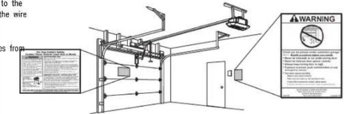
Exterior view of a LiftMaster device with visible branding and logo (no readable text beyond branding)• Please read this manual and the safety materials care
- Periodic checks of the garage door opener are required to ensure safe operation.
- This garage door opener is ONLY compatible® with my and Security+ 2 accessories.
- DO NOT install on a one-piece door if using devices features providing unattended close. Unattended devices and features are to be used ONLY with sectional dc
- Attach warning labels to the location indicated on label
Download the myQ® App


LiftMaster
300 Windsor Drive
Oak Brook, IL 60523
LiftMaster®
Table of Contents
Preparation
Carton Inventory 87504-267 7
Carton Inventory 87802 7
Carton Inventory 84504R 8
Carton Inventory 84505R 9
Carton Inventory 84602 10
Assembly
87504-267, 84504R, 84505R 11
84602 12
87802 13
Installation
Control Panel
Install the Protector System
Power
Adjustments
Battery Backup
Operation
6
11
15
23
25
29
31
33
35
Maintenance
Troubleshooting
Accessories
Warranty
Repair Parts
Model 87504-267
Model 87802
Model 84602
Model 84504R
Model 84505R
43
44
46
47
50
50
52
54
56
58
Preparation
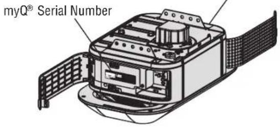
myQ® Serial Number
Write down the following information for future reference:
myQ ^® Serial Number:
Product Serial Number:
Date of Purchase:
/ /
Product Serial Number
text_image
myQ® Serial NumberSafety Symbol and Signal Word Review
This garage door opener has been designed and tested to offer safe service provided it operated, maintained and tested in strict accordance with the instructions and warnings cont manual.
When you see these Safety Symbols and Signal Words on the following pages, they will possibility of serious injury or death if you do not comply with the warnings that accom hazard may come from something mechanical or from electric shock. Read the warnings c

Mechanical

Electrical
When you see this Signal Word on the following pages, it will alert you to the possibility of damage to your garage door and/or the garage door opener if you do not comply with the cautionary statements that accompany it. Read them carefully.


WARNING: This product can expose you to chemicals including lead, which are known to the State of California to cause cancer or birth defects or other reproductive harm. For more information go to www.P65Warnings.ca.gov
Unattended Operation
The Timer-to-Close (TTC) feature, the myQ® App, and myQ® Garage Door and Gate Monitor are examples of unattended close and are to be used ONLY with sectional doors. Any device or feature that allows the door to close without being in the line of sight of the door is considered unattended close. The Timer-to-Close (TTC) feature, the myQ® App, and any other myQ® devices are to be used ONLY with sectional doors.
The images throughout this User's Guide are for reference only and you may look different.
Preparation
Before You Connect with Your Smartphone
Monitor and control your garage door from anywhere using the myQ® App. You will need:
- Wi-Fi® enabled smartphone, tablet or laptop
- Broadband Internet Connection
- Wi-Fi ^TM signal in the garage (2.4 GHz, 802.11b/g/n required)
- Password for your home network (router's main account, not guest network)
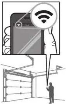
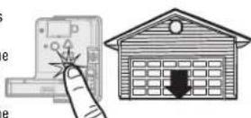
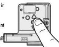
TEST THE WI-FI® SIGNAL STRENGTH
Make sure your mobile device is connected to your Wi-Fi® network. Hold your mobile device in the place your garage door opener will be installed and check the Wi-Fi® signal strength.
text_image
Diagram illustrating smart home connectivity with a smartphone displaying Wi-Fi icon and a person holding a device, likely for health or security monitoring.Check Signal Strength. If you see:


Wi-Fi signal is strong.
The garage door opener will connect to your Wi-Fi network.

Wi-Fi signal is weak.
The garage door opener may connect to your Wi-Fi network. If not, try one of the options below to improve the Wi-Fi signal:

No Wi-Fi signal.
The garage door opener will not be able to connect to your Wi-Fi network. Try one of the options below to improve the Wi-Fi signal:
- Move your router closer to the garage door opener to minimize interference from walls and other objects
- Buy a Wi-Fi range extender
For compatible router specifications and help, visit support.liftmaster.com.
See page 37 to connect the garage door opener to a mobile device.
Check the Door

WARNING
To prevent possible SERIOUS INJURY or DEATH:
- ALWAYS call a trained door systems technician if garage door binds, sticks, or is out of balance. An unbalanced garage door may NOT reverse when required.
- NEVER try to loosen, move or adjust garage door, door springs, cables, pulleys, brackets or their hardware, ALL of which are under EXTREME tension.
- Disable ALL locks and remove ALL ropes connected to garage door BEFORE installation and operating garage door opener to avoid entanglement.
- DO NOT install on a one-piece door if using devices or features providing unattended close. Unattended devices and features are to be used ONLY with sectional doors.

CAUTION
To prevent damage to garage door and opener:
• ALWAYS disable locks BEFORE installing and operating the opener.
• ONLY operate garage door opener at 120V, 60 Hz to avoid malfunction and damage.
Before you begin:
- Disable locks and remove any ropes connected to the garage door.
- Lift the door halfway up. Release the door. If balanced, it should stay in supported entirely by its springs.
- Raise and lower the door to check for binding or sticking. If your door bit sticks, or is out of balance, call a trained door systems technician.
- Check the seal on the bottom of the door. Any gap between the floor and bottom of the door must not exceed 1/4" (6 mm). Otherwise, the safety system may not work properly.
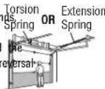
- The opener should be installed above the center of the door. If there is a torsion spring or center bearing plate in the way of the header bracket, it may be installed within 4 feet (1.2 m) to the left or right of the door center. See page 16.
Preparation
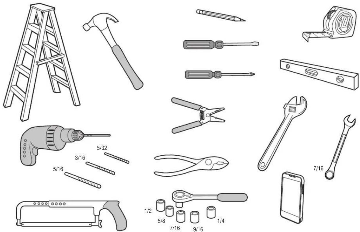
ToolsNeeded
Preparation
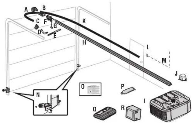
Carton Inventory 87504-267
Accessories will vary depending on the garage door opener model purchased. Depending on your spe model, other accessories may be included with your garage door opener. The instructions for these a will be attached to the accessory and are not included in this manual. The images throughout this manual are for reference and your product may look different.
A. Header bracket
B. Pulley and bracket
C. Door bracket
D. Curved door arm
G. Emergency release rope and handle
H. Rail
J. Pulley cover with hex screws
K. Belt
L. Control Panel®
M. White and red/white wire
N. The Protector System®
Safety reversing sensors with white and white/black wire attached: Sending senor (1), receiving sensor (1), and safety sensor brackets (2)
O. Safety labels and literature
P. Rail grease
Q. Remote control (2)
R. Battery
S. Keyless Entry
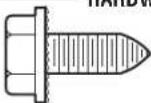
RAIL HARDWARE
Washed Bolt 5/16"-18 x 1/2" (2) [mounted in the top of the garage door opener]
INSTALLATION HARDWARE
Hex Bolt 5/16"-18 x 7/8" (4) Lock Washer 5/16" (4)
Lag Screw 5/16"-9 x 1-5/8" (2) Self-Threading Screw 1/4"-14 x 5/8" (2)
Clevis Pin 5/16" x 2-3/4" (1) Ring Fastener (3)
Clevis Pin 5/16" x 1-1/4" (1) Hex Screw 10-24 (2)
Clevis Pin 5/16" x 1" (1) Wing Nut (2)
Nut 5/16"-18 (4)
CONTROL PANEL HARDWARE
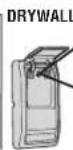
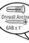
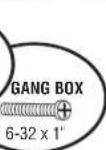
Screw 6AB x 1-1/4" (2) Drywall Anchors (2) Screw 6-32 x 1" (2)
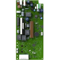
text_image
Diagram of a mechanical or electrical device with labeled components and an inset photo showing a device with internal components.Preparation
Carton Inventory 87802
Accessories will vary depending on the garage door opener model purchased. Depending on your specific model, other accessories may be included with your garage door opener. The instructions for these acces will be attached to the accessory and are not included in this manual. The images throughout this manual are for reference and your product may look different.
A. Header bracket
B. Pulley and bracket
C. Door bracket
D. Curved door arm
E. Straight door arm
F. Trolley
G. Emergency release rope and handle
H. Rail
I. Garage door opener
J. Chain spreader with hex screws
K. Chain
L. Control Panel®
M. White and red/white wire
N. The Protector System®
Safety reversing sensors with white and white/black wire attached: Sending senor (1), receiving sensor (1), and safety sensor brackets (2)
O. Safety labels and literature
P. Rail grease
Q. Remote control(s)
R. Battery
S. Chassis support bracket
Hardware
Chassis Support Bracket Hardware Chain Spreader Hardware
Screw #8-32 x 3/8" (1) Screw #8-32 x 3/8" (2)
Hex Bolts 1/4"-20 x 5/8" (2) Rail Hardware
Lock Washers (2)
Washed Bolt 5/16"-18 x 1/2" (2)
Washed Bolts (mounted in the top of the garage door opener)
Installation Hardware
Hex Bolt 5/16"-18 x 7/8" (4) Self-Threading Screw 1/4"-14 x 5/8" (2)
datesScrew 5/16"-9 x 1-5/8" (2) Ring Fastener (3)
Clevis Pin 5/16" x 2-3/4" (1) Hex Screw 10-24 (2)
Clevis Pin 5/16" x 1-1/4" (1) Wing Nut (2)
Clevis Pin 5/16" x 1" (1) Hex Bolt 1/4"-20 x 5/8" (2)
Nut 5/16"-18 (4) Lock Nut 1/4"-20 (2)
Lock Washer 5/16" (4)
Lag Screw 1/4" x 1-1/2" (4)
Control Panel Hardware
Screw 6AB x 1" (2)
Drywall Anchors (2)
Screw 6-32 x 1" (2)
text_image
Technical diagram of a mechanical assembly with labeled components and a zoomed-in view showing internal components.Power
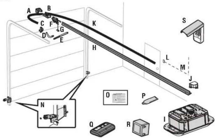
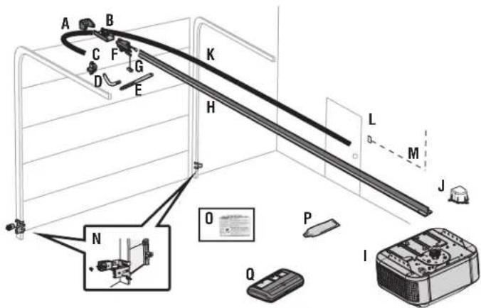
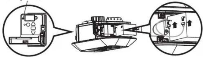
Carton Inventory 84504R
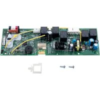
Accessories will vary depending on the garage door opener model purchased. Depending on your specific model, other accessories may be included with your garage door opener. The instructions for these acces will be attached to the accessory and are not included in this manual. The images throughout this manual are for reference and your product may look different.
A. Header bracket
B. Pulley and bracket
C. Door bracket
D. Curved door arm
E. Straight door arm
F. Trolley
G. Emergency release rope and handle
H. Rail
I. Garage door opener
J. Pulley cover with hex screws
K. Belt
L. Control panel
M. White and red/white wire
N. The Protector System®
Safety reversing sensors with white and white/black wire attached: Sending senor (1), receiving sensor (1), and safety sensor brackets (2)
O. Safety labels and literature
P. Rail grease
Q. Remote control
R. Battery
RAIL HARDWARE
Washed Bolt 5/16"-18 x 1/2" (2) (mounted in the top of the garage door opener) Lock Washer 5/16" (4)
Hex Bolt 5/16"-18 x 7/8" (4) Self-Threading Screw 1/4"-14 x 5/8" (2)
Lag Screw 5/16"-9 x 1-5/8" (2) Ring Fastener (3)
Clevis Pin 5/16" x 2-3/4" (1) Hex Screw 10-24 (2)
Clevis Pin 5/16" x 1-1/4" (1) Wing Nut (2)
Clevis Pin 5/16" x 1" (1)
Nut 5/16"-18 (4)
CONTROL PANEL HARDWARE
Screw 6AB x 1-1/4" (2) Drywall Anchors (2)
Screw 6-32 x 1" (2)
text_image
Diagram of a mechanical or electrical device with labeled components and a zoomed-in view showing internal components.Power
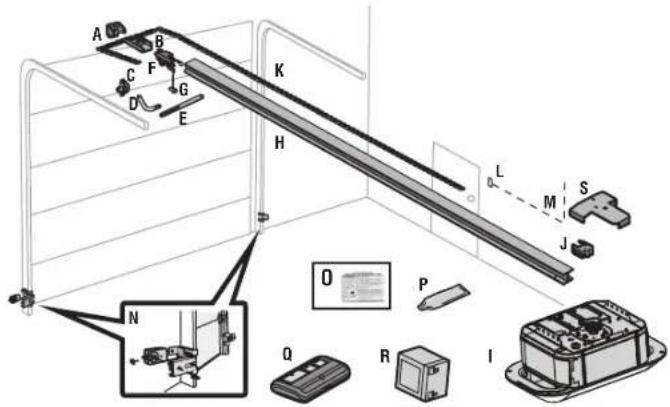
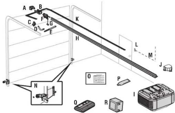
Carton Inventory 84505R
Accessories will vary depending on the garage door opener model purchased. Depending on your specific model, other accessories may be included with your garage door opener. The instructions for these acces will be attached to the accessory and are not included in this manual. The images throughout this manual are for reference and your product may look different.
A. Header bracket
B. Pulley and bracket
C. Door bracket
D. Curved door arm
E. Straight door arm
F. Trolley
G. Emergency release rope and handle
H. Rail
I. Garage door opener
J. Pulley cover with hex screws
K. Belt
L. Control panel
M. White and red/white wire
N. The Protector System®
Safety reversing sensors with white and white/black wire attached: Sending senor (1), receiving sensor (1), and safety sensor brackets (2)
O. Safety labels and literature
P. Rail grease
Q. Remote control
RAIL HARDWARE
Washed Bolt 5/16"-18 x 1/2" (2) (mounted in the top of the garage door opener) Lock Washer 5/16" (4)
Hex Bolt 5/16"-18 x 7/8" (4) Self-Threading Screw 1/4"-14 x 5/8" (2)
Lag Screw 5/16"-9 x 1-5/8" (2) Ring Fastener (3)
Clevis Pin 5/16" x 2-3/4" (1) Hex Screw 10-24 (2)
Clevis Pin 5/16" x 1-1/4" (1) Wing Nut (2)
Clevis Pin 5/16" x 1" (1)
Nut 5/16"-18 (4)
CONTROL PANEL HARDWARE
Screw 6AB x 1-1/4" (2) Drywall Anchors (2)
Screw 6-32 x 1" (2)
text_image
A B C F G D E K H L M J N O P Q IPreparation
Carton Inventory 84602
Accessories will vary depending on the garage door opener model purchased. Depending on your specific model, other accessories may be included with your garage door opener. The instructions for these acces will be attached to the accessory and are not included in this manual. The images throughout this manual are for reference and your product may look different.
A. Header bracket
B. Pulley and bracket
C. Door bracket
D. Curved door arm
G. Emergency release rope and handle
H. Rail
J. Sprocket cover with hex screws
K. Chain
L. Control panel
M. White and red/white wire
N. The Protector System® Safety reversing sensors with white and white/black wire attached: Sending senor (1), receiving sensor (1), and safety sensor brackets (2)
O. Safety labels and literature
P. Remote control
Q. Remote control
R. Battery
RAIL HARDWARE
Washed Bolt 5/16"-18 x 1/2" (2) (mounted in the top of the garage door opener) Lock Washer 5/16"-16 (4)
Hex Bolt 5/16"-18 x 7/8" (4) Self-Threading Screw 1/4"-14 x 5/8" (2)
Lag Screw 5/16"-9 x 1-5/8" (2) Ring Fastener (3)
Clevis Pin 5/16" x 2-3/4" (1) Hex Screw 10-24 (2)
Clevis Pin 5/16" x 1-1/4" (1) Wing Nut (2)
Clevis Pin 5/16" x 1" (1)
Nut 5/16"-18 (4)
CONTROL PANEL HARDWARE
Screw 6AB x 1-1/4" (2) Drywall Anchors (2) Screw 6-32 x 1" (2)
text_image
Diagram of a mechanical or electrical device with labeled components and an inset image showing a device with parts O, P, R, Q, N, H, K, L, M.Assembly
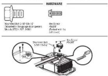
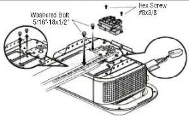
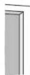
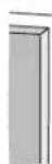
1 Attach the Belt Rail to the Garage Door Opener 87504-267, 84504R, 84505R

WARNING
To avoid possible SERIOUS INJURY to finger from moving garage door opener:
• ALWAYS keep hand clear of sprocket while operating opener.
- Securely attach sprocket cover BEFORE operating.

CAUTION
To avoid SERIOUS damage to garage door opener, use ONLY those bolts/fasteners mounted in the the opener.
NOTE: ONLY use the bolts removed from the garage door opener. Place the garage door opener on the packing material to prevent scratching.
- Models 87504-267 and 84505R Remove the two bolts from the top of the garage door opener.
- Align the holes in the rail with the holes in the garage door opener..
- Fasten the rail with the previously mentioned bolts. Cut away and discard the tape and Styrofoam around the rail.
- Position the belt around the garage door opener sprocket.
- Position the sprocket cover over the garage door opener sprocket and attach with hex screws.
text_image
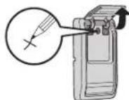
HARDWARE Watered Bolt 30°-54' (12" (Measured in the range door spenter) Madder (87°-92°, 16°) Heat Diver Pulsar Thermal with the Locked Watered Bolt 30°-54' (12" Heat Diver Pulsar2 Tighten the Belt
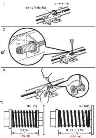
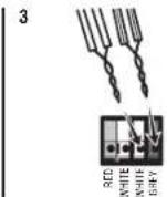
- Insert a flathead screwdriver tip into one of the nut ring slots and brace it firmly against the trolley.
- Tighten the spring trolley nut with an adjustable wrench or a 7/16" open end wrench about a quarter turn until the spring releases and snaps the nut ring against the trolley. This sets the spring to optimum bell tension.
text_image
Spring Trolley Nut 11.0" (200K UFS) 2 Nut ring slot 3 Nut Ring SCTOFE (2.5 cm) Nut Ring AFTER RELEASE t=1.5" (2.18 cm)Assembly
1 Attach Chain Rail to the Garage Door Opener Model 84602

WARNING
To avoid possible SERIOUS INJURY to finger from moving garage door opener:
• ALWAYS keep hand clear of sprocket while operating opener.
- Securely attach sprocket cover BEFORE operating.

CAUTION
To avoid SERIOUS damage to garage door opener, use ONLY those bolts/fasteners mounted in the top of the opener.
NOTE: ONLY use the bolts removed from the garage door opener. Place the garage door opener on the packing material to prevent scratching.
- Remove the two bolts from the top of the garage door opener.
- Align the holes in the rail with the holes in the garage door opener.
- Fasten the rail with the previously mentioned bolts. Cut away and discard the tape and Styrofoam around the rail.
- Position the chain around the garage door opener sprocket.
- Position the sprocket cover over the garage door opener sprocket and attach with hex screws.
Washed Bolt 5/16"-18x1/2"
(Mounted in the garage door opener)
Models 87504-267. 84501
HARDWARE

Hex Screw
8×3/8"
(Packed with the
sprocket cover)
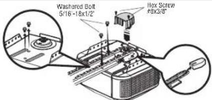
text_image
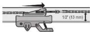
Washed Bolt 5/16-18x1/2" Flex Screw 49x3/8"2 Tighten the Chain for Model 84602
- Loosen the inner nut and lock washer on the trolley threaded shaft.
- Tighten the outer nut until the chain is a 1/2" above the base of the rail at the midpoint of the rail.
- Re-tighten the inner nut.
Slack in the chain is normal when the door is closed. No readjustment is necessary.
Assembly
1 Attach the I-Beam Chain Rail to the Garage Door Opener 2 Attach the Chassis Support Bracket 87802

CAUTION
To avoid SERIOUS damage to garage door opener, use ONLY those bolts/fasteners mounted in the top the opener.
NOTE: ONLY use the bolts removed from the garage door opener. Place the garage door opener on the packing material to prevent scratching.
- Remove the two bolts from the top of the garage door opener.
- Align the holes in the rail with the holes in the garage door opener.
- Fasten the rail with the previously mentioned bolts. Cut away and discard the tape and Styrofoam from around the rail.
- Position the chain around the garage door opener sprocket.
- Attach the chain spreader to the garage door opener with screws.
- Guide the chain around the selected groove in the chain spreader.
HARDWARE
Washed Bolt 5/16'-18x1/2" (Mounted in the garage door opener)

Hex Screw
8x3/8"
(Packed with the sprocket cover)
text_image
Washed Bolt 5/10'-18x1/2' Hex Screw #8x3/8
WARNING
To avoid possible SERIOUS INJURY to finger from moving garage door opener:
f • ALWAYS keep hand clear of sprocket while operating opener.
- Securely attach sprocket cover BEFORE operating.
- Position the chassis support bracket on the unit.
- Attach the bracket to the rail with 1/4"-20 x 5/8" hex bolts and lock washers. Do not overtighten.
- Attach the bracket to the opener by inserting a 5/16"-18 x 1/2" washed screw through a hole in each s flange and a matching hole in the bracket. Complete the connection by inserting the #8-32 x 3/8" screw through the back flange and the hole in rail support.
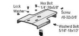
text_image
Lock Washer Hex Bolt 1/4"-20x5/8" Screw #8-32x3/8" Washerd Bolt 5/16"-18x1/2"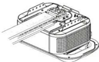
natural_image
Technical line drawing of a mechanical component with internal structure and mounting base (no text or symbols)Assembly
3 Tighten the Chain
- Loosen the inner nut and lock washer on the trolley threaded shaft.
- Tighten the outer nut until the chain is a 1/2" above the base of the rail at the midpoint of the rail.
- Re-tighten the inner nut.
Slack in the chain is normal when the door is closed. No readjustment is necessary.
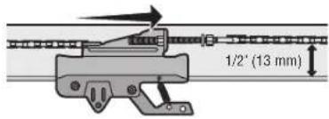
text_image
1/2" (13 mm)Installation
IMPORTANT INSTALLATION INSTRUCTIONS
WARNING
To reduce the risk of SEVERE INJURY or DEATH:
- READ AND FOLLOW ALL INSTALLATION WARNINGS AND INSTRUCTIONS.
- Install garage door opener ONLY on properly balanced and lubricated garage door. An improperly balanced door may NOT reverse when required and could result in SEVERE INJURY or DEATH.
- ALL repairs to cables, spring assemblies and other hardware MUST be made by a trained door systems technician BEFORE installing opener.
- Disable ALL locks and remove ALL ropes connected to garage door BEFORE installing opener to avoid entanglement.
- Where possible, install the door opener 7 feet (2.13 m) or more above the floor.
- Mount the emergency release within reach, but at least 6 feet (1.83 m) above the floor and avoiding contact with vehicles to avoid accidental release.
- NEVER connect garage door opener to power source until instructed to do so.
-
NEVER wear watches, rings or loose clothing while installing or servicing opener. They could be caught in garage door or opener mechanisms.
-
Install wall-mounted garage control panel:
• within sight of the garage door. - out of reach of small children at a minimum height of 5 feet (1.5 m) above floors, landings, steps or any other adjacent walking surface.
• away from ALL moving parts of the door. - Place entrapment warning label on wall next to garage control panel in a prominent location.
- Place emergency release/safety reverse test label in plain view on inside of garage door.
- Upon completion of installation, test safety reversal system. Door MUST reverse on contact with a 1-1/2" (3.8 cm) high object (or a 2x4 laid flat) on the floor.
-
DO NOT install on a one-piece door if using devices or features providing unattended close. Unattended devices and features are to be used ONLY with sectional doors.
-
SAVE THESE INSTRUCTIONS.
Installation
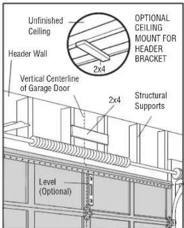
1 Determine the Header Bracket Location

WARNING
To prevent possible SERIOUS INJURY or DEATH:
- Header bracket MUST be RIGIDLY fastened to structural support on header wall or ceiling, otherwise garage door might NOT reverse when required. DO NOT install header bracket over drywall.
- Concrete anchors MUST be used if mounting header bracket or 2x4 into masonry.
- NEVER try to loosen, move or adjust garage door, springs, cables, pulleys, brackets, or their hardware, ALL of which are under EXTREME tension.
- ALWAYS call a trained door systems technician if garage door binds, sticks, or is out of balance. An unbalanced garage door might NOT reverse when required.
Close the door and mark the inside vertical centerline of the garage door.
Extend the line onto the header wall above the door. You can fasten the header bracket within 4 feet (1.22 m) of the left or right of the door center only if a torsion spring or center bearing plate is in the way; or you can attach it to the ceiling when clearance is minimal. (It may be mounted on the wall upside down if necessary, to gain approximately 1/2" (1 cm). If you need to install the header bracket on a 2x4 (on wall or ceiling), use lag screws (not provided) to securely fasten the 2x4 to structural supports.
Open your door to the highest point of travel as shown. Draw an intersecting horizontal line on the header wall 2" (5 cm) above the high point. This height will provide travel clearance for the top edge of the door.
NOTE: If the total number of inches exceeds the height available in your garage, use the maximum height possible, or refer to page 17 for ceiling installation.
text_image
Unfinished Ceiling Header Wall 2x4 OPTIONAL CEILING MOUNT FOR HEADER BRACKET Vertical Centerline of Garage Door 2x4 Structural Supports Level (Optional)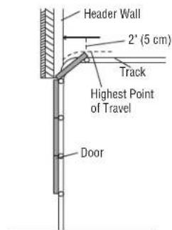
text_image
Header Wall 2" (5 cm) Track Highest Point of Travel DoorSectional door with curved track
Installation
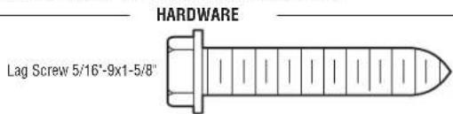
2 Install the Header Bracket
You can attach the header bracket either to the wall above the garage door, or to the ceiling. Follow instructions which will work best for your particular requirements. Do not install the header bracket over drywall. If installing into masonry, use concrete anchors (not provided).
text_image
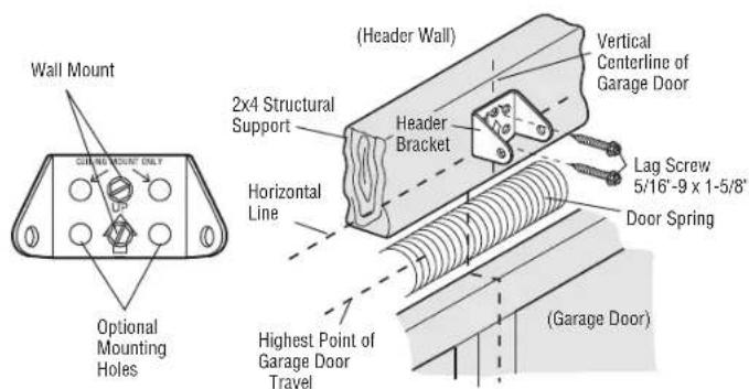
HARDWARE Lag Screw 5/16"-9x1-5/8"OPTION A - WALL INSTALLATION
- Center the bracket on the vertical centerline with the bottom edge of the bracket on the horizontal shown (with the arrow pointing toward the ceiling).
text_image
Wall Mount QUARTING MOUNT ONLY Optional Mounting Holes (Header Wall) 2x4 Structural Support Header Bracket Horizontal Line (Highest Point of Garage Door Travel) (Garage Door) Vertical Centerline of Garage Door Lag Screw 5/16"-9 x 1-5/8" Door SpringOPTION B- CEILING INSTALLATION
-
Extend the vertical centerline onto the ceiling as shown.
-
Mark the side holes. Drill 3/16" pilot holes and fasten bracket securely to a structural support with the hardware provided.
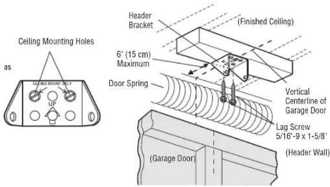
text_image
Ceiling Mounting Holes as Ceiling Mount DLY UP Header Bracket (Finished Ceiling) 6" (15 cm) Maximum Door Spring Vertical Centerline of Garage Door Lag Screw 5/16"-9 x 1-5/8" ( Garage Door ) ( Header Wall )Installation
3 Attach the Rail to the Header Bracket
- Align the rail with the header bracket. Insert the clevis pin through the holes in the header bracket Secure with the ring fastener.
NOTE: Use the packing material as a protective base for the garage door opener.
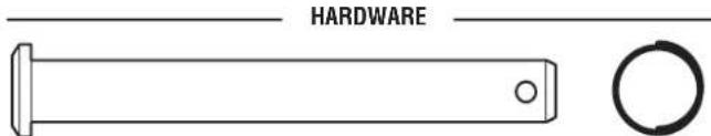
text_image
HARDWAREClevis Pin 5/16' x 2-3/4' Ring Fastener
text_image
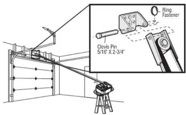
Ring Fastener Clevis Pin 5/16" X 2-3/4"4 Position the Garage Door Opener
and rail.
CAUTION
To prevent damage to garage door, rest garage door opener rail on 2x4 placed on top section of door.
- Remove the packing material and lift the garage door opener onto a ladder.
- Fully open the door and place a 2x4 (laid flat) under the rail.
A 2x4 is ideal for setting the distance between the rail and the door. If the ladder is not tall enough you w help at this point. If the door hits the trolley when it is raised, pull the trolley release arm down to disconnect inner and outer trolley. Slide the outer trolley toward the garage door opener. The trolley can remain disconnected until instructed.
text_image
Connected DisconnectedInstallation
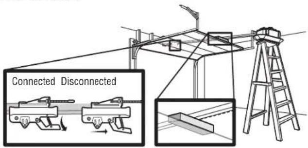
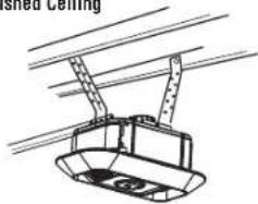
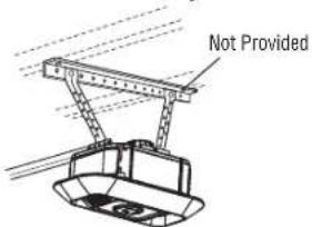
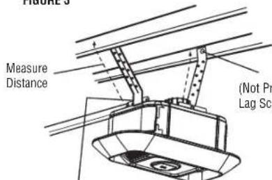
5 Hang the Garage Door Opener

WARNING
To avoid possible SERIOUS INJURY from a falling garage door opener, fasten it SECURELY to structural supports of the garage. Concrete anchors MUST be used if installing ANY brackets into masonry.
Hanging your garage door opener will vary depending on your garage. Two representative installations are shown. Yours may be different. Hanging brackets should be angled (Figure 1) to provide rigid support. On finished ceilings (Figure 2), attach a sturdy metal bracket to structural supports before installing the opener. This bracket and fastening hardware are not provided.
- Measure the distance from each side of the motor unit to the structural support.
- Cut both pieces of the hanging bracket to required lengths.
- Drill 3/16" pilot holes in the structural supports.
- Attach one end of each bracket to a support with 5/16"-18 x 1-7/8" lag screws (not provided).
- Fasten the opener to the hanging brackets with 5/16"-18 x 7/8" hex bolts, lock washers and nuts.
- Check to make sure the rail is centered over the door (or in line with the header bracket if the bracket is not centered above the door).
- Remove the 2x4. Operate the door manually. If the door hits the rail, raise the header bracket. NOTE: DO NOT connect power to opener at this time.
HARDWARE


Hex Bolt 5/16"-18x7/8" Nut 5/16"-18 Lock Washer 5/16
FIGURE 1
Unfinished Ceiling
natural_image
Diagram of a cable car with overhead suspension and support structure (no text or symbols)FIGURE 2
Finished Ceiling
text_image
Not ProvidedFIGURE 3
text_image
Measure Distance (Not Pr Lag ScrHex Bolt 5/16"-18x7/8", Lock Washer 5/16", Nut 5/16"-18
Installation
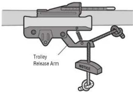
6 Attach the Emergency Release Rope and Handle
WARNING
To prevent possible SERIOUS INJURY or DEATH from a falling garage door:
- If possible, use emergency release handle to disengage trolley ONLY when garage door is CLOSED. Weak or broken springs or unbalanced door could result in an open door falling rapidly and/or unexpectedly.
- NEVER use emergency release handle unless garage doorway is clear of persons and obstructions.
-
NEVER use handle to pull door open or closed. If rope knot becomes untied, you could fall.
-
Insert one end of the emergency release rope through the handle. Make sure that "NOTICE" is right side up. Secure with an overhand knot at least 1" (2.5 cm) from the end of the rope to prevent slipping.
- Insert the other end of the emergency release rope through the hole in the trolley release arm. Mount the emergency release within reach, but at least 6 feet (1.83 m) above floor, avoiding contact with vehicles to prevent accidental release and secure with an overhand knot.
NOTE: If it is necessary to cut the emergency release rope, seal the cut end with a match or lighter to prevent unraveling. Ensure the emergency release rope and handle are above the top of all vehicles to avoid entanglement.
text_image
Trolley Release Arm NOTICEInstallation
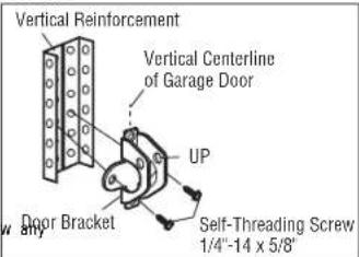
7 Install the Door Bracket

CAUTION
Fiberglass, aluminum or lightweight steel garage doors WILL REQUIRE reinforcement BEFORE installation of door bracket. Contact the garage door manufacturer or installing dealer for opener reinforcement instructions or reinforcement kit.
A horizontal and vertical reinforcement is needed for lightweight garage doors (fiberglass, aluminum, steel, doors with glass panel, etc.) (not provided). A horizontal reinforcement brace should be long enough to be secured to two or three vertical supports. A vertical reinforcement brace should cover the height of the top panel. Contact the garage door manufacturer or installing dealer for opener reinforcement instructions or reinforcement kit.
natural_image
Technical diagram of a mechanical assembly with directional arrows indicating movement (no text or symbols)NOTE: Many door reinforcement kits provide for direct attachment of the clevis pin and door arm. In this case you will not need the door bracket; proceed to the next step.
SECTIONAL DOORS
- Center the door bracket on the previously marked vertical centerline used for the header bracket installation. Note correct UP placement, as stamped inside the bracket.
- Position the top edge of the bracket 2"-4" (5-10 cm) below the top edge of the door, OR directly structural support across the top of the door.
- Mark, drill holes and install as follows, depending on your door's construction:
Metal or light weight doors using a vertical angle iron brace between the and the door bracket:
- Drill 3/16" fastening holes. Secure the door bracket using the two self threading screws. (Figure 1)
• Alternately, use two 5/16"-18x2" bolts, lock washers and nuts (not provided). (Figure 2)
Metal, insulated or light weight factory reinforced doors:
- Drill 3/16" fastening holes. Secure the door bracket using the self-threading screws. (Figure 3)
Wood Doors:
- Use top and bottom or side to side door bracket holes. Drill 5/16" holes through the door and secure bracket with 5/16"-18 x 2" carriage bolts, lock washers and nuts (not provided). (Figure 4)
NOTE: The 1/4"-14 x 5/8" self-threading screws are not intended for use on wood doors.
HARDWARE
Self-Threading Screw 1/4"-14 x 5/8"
FIGURE 1
text_image
Vertical Reinforcement Vertical Centerline of Garage Door UP Door Bracket Self-Threading Screw 1/4"-14 x 5/8"FIGURE 3
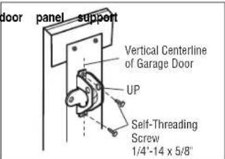
text_image
door panel support Vertical Centerline of Garage Door UP Self-Threading Screw 1/4'-14 x 5/8"FIGURE 2
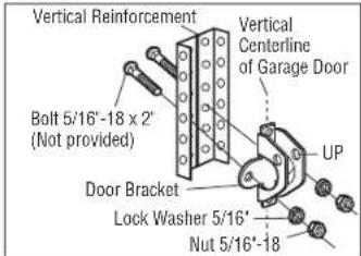
text_image
Vertical Reinforcement Bolt 5/16'-18 x 2" (Not provided) Vertical Centerline of Garage Door UP Door Bracket Lock Washer 5/16' Nut 5/16'-18FIGURE 4
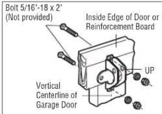
text_image
Bolt 5/16'-18 x 2' (Not provided) Inside Edge of Door or Reinforcement Board UP Vertical Centerline of Garage DoorInstallation
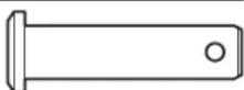
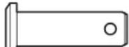
8 Connect the Door Arm to the Trolley
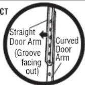
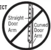
IMPORTANT: The groove on the straight door arm MUST face away from the curved door arm.
- Close the door. Disconnect the trolley by pulling the emergency release handle. Slide the outer trolley back (away from the door) about 2" (5 cm).
- Attach the straight door arm to the outer trolley using the clevis pin. Attach with the ring fastener.
- Attach the curved door arm to the door bracket using the clevis pin. Attach with the ring fastener.
- Align the straight door arm with the curved door arm. Select two aligned holes (as far apart as possible) and attach using the bolts, nuts and lock washers.
NOTE: If the holes do not line up, reverse the straight door arm. Select two aligned holes (as far apart as possible) and attach using the bolts, nuts and lock washers.
- Pull the emergency release handle toward the garage door opener until the trolley release arm is horizontal. The trolley will re-engage automatically when the garage door opener is activated.
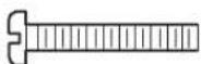
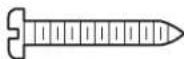
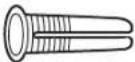
Hex Bolt 5/16"-18 x 7/8"
HARDWARE

Lock Washer 5/16"
Clevis Pin 5/16" x 1-1/4"

Nut 5/16"-18

Ring Fastener
Clevis Pin 5/16" x 1"
CORRECT
INCORRECT
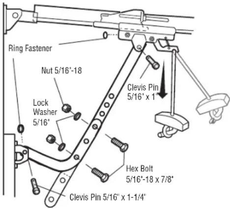
text_image
Ring Fastener Nut 5/16'-18 Lock Washer 5/16' Clevis Pin 5/16' x 1' Hex Bolt 5/16"-18 x 7/8" Clevis Pin 5/16" x 1-1/4"Control Panel
1 Install the Control Panel


WARNING
To prevent possible SERIOUS INJURY or DEATH from electrocution:
- Be sure power is NOT connected BEFORE installing control panel.
- Connect control panel ONLY to 12 VOLT low voltage wires.
To prevent possible SERIOUS INJURY or DEATH from a closing garage door:
• Install control panel within sight of garage door, out of reach of small children at a minimum 5 feet (1.5 m) above floors, landings, steps or any other adjacent walking surface, and away from moving parts of door. - NEVER permit children to operate or play with control panel push buttons or remote control transmitters.
- Activate door ONLY when it can be seen clearly, is properly adjusted, and there are no obstruct door travel.
- ALWAYS keep garage door in sight until completely closed. NEVER permit anyone to cross path closing garage door.
INTRODUCTION
Compatible with myQand Security+ 2.0 accessories, see page 37. Your garage door opener is compatible up to 2 Smart Control Panels or 4 of any other Security+ 2.0 control panels. NOTE: Older control panels and third party products are not compatible.
Install door control within sight of garage door, out of reach of small children at a minimum height of (1.5 m) above floors, landings, steps or any other adjacent walking surface, and away from ALL moving door. For gang box installations it is not necessary to drill holes or install the drywall anchors. Use the holes in the gang box.
NOTE: Your product may look different than the illustrations.
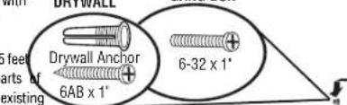
Screw 6-32 x 1" (2)
Drywall
Anchors (2)
HARDWARE
Screw 6AB x 1' (2)
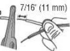
- Strip 7/16" (11 mm) of insulation from one end of the wire and separate the wires.
- Connect one wire to each of the two screws on the back of the control panel. The wires can be connect to either screw.
PRE-WIRED INSTALLATIONS: Choose any two wires to connect, note which wires are used so the correct wires are connected at the garage door opener in a later step.
- Mark the location of the bottom mounting hole and drill a 5/32" hole.
- Install the bottom screw, allowing 1/8" (3 mm) to protrude from the wall.
- Position the bottom hole of the control panel over the screw and slide down into place.
- Lift the push bar up and mark the top hole.
ht. Remove the control panel from the wall and drill a 5/32" hole for the top screw.
B. Position the bottom hole of the control panel over the screw and slide down into place. Attach the top screw.
1
23
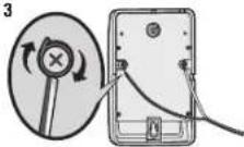
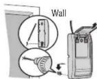
4-5
DRYWALL
text_image
Drywall Anchor 6AB x 1' 6-32 x 1'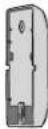
6
7

5
Control Panel
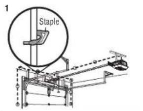
2 Wire the Control Panel to the Garage Door Opener
PRE-WIRED INSTALLATIONS: When wiring the control panel to the garage door opener make sure you use the same wires that are connected to the control panel.
- Run the white and red/white wire from the control panel to the garage door opener. Attach the wire wall and ceiling with staples (not applicable for gang box or pre-wired installations). Do not pierce with the staple as this may cause a short or an open circuit.
- Strip 7/16" (11 mm) of insulation from the end of the wire near the garage door opener.
- Connect the wire to the red and white terminals on the garage door opener. To insert or release the terminal, push in the tab with screwdriver tip.
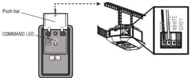
text_image
Push bar COMMAND LED LED WHITE GREY3 Attach the Warning Labels
- Attach the entrapment warning label on the wall near the control panel with tacks or staples.
- Attach the manual release/safety reverse test label in a visible location on the inside of the garage door.
to the
he wire
to
he
he
he
he
he
he
he
he
he
to
he
he
he
he
he
he
he
he
he
he
he
he wire
he wire
he wire
he wire
he wire
(五) 2017年1月1日
he wrc
[Non-Text]
The Ground Truth image displays a single, solid horizontal line. According to Rule 2 (UNDERSCORE & LINE RULES), this is a stylistic or background line, not a placeholder underscore. Therefore, the OCR result must ignore it and output nothing or only meaningful text. The provided OCR content is "____", which consists of four underscores. This is an incorrect interpretation of the line as a placeholder, violating the rule that stylistic lines must be ignored. The OCR has hallucinated underscores where none should exist based on the GT's visual context. Hence, the OCR result is inconsistent with the Ground Truth.
[Non-Text]
2.2
es from-
es from-
es from-
es from-
es from-
[Non-Text]
[Non-Text]
[Non-Text]
[Non-Text]
[Non-Text]
[Non-Text]
.5-1704
(1)
(1)
(1)
(1)
(1)
es from
es from
es from
es from
[Non-Text]
[Non-Text]
[Non-Text]
[Non-Text]
[Non-Text]
[Non-Text]
[Non-Text]
[Non-Text]
[Non-Text]
[Non-Text]
[Non-Text]
[Non-Text]
[Non-Text]
[Non-Text]
[Non-Text]
[Non-Text]
[Non-Text]
[Non-Text]
text_image
to the the wire es from WARNING 1. To be a reliable safety measure, please check 2. Check the safety measure, please check 3. Check the safety measure, please check 4. Check the safety measure, please check 5. Check the safety measure, please check 6. Check the safety measure, please check 7. Check the safety measure, please check 8. Check the safety measure, please check 9. Check the safety measure, please check 10. Check the safety measure, please check 11. Check the safety measure, please check 12. Check the safety measure, please check 13. Check the safety measure, please check 14. Check the safety measure, please check 15. Check the safety measure, please check 16. Check the safety measure, please check 17. Check the safety measure, please check 18. Check the safety measure, please check 19. Check the safety measure, please check 20. Check the safety measure, please check 21. Check the safety measure, please check 22. Check the safety measure, please check 23. Check the safety measure, please check 24. Check the safety measure, please check 25. Check the safety measure, please check 26. Check the safety measure, please check 27. Check the safety measure, please check 28. Check the safety measure, please check 29. Check the safety measure, please check 30. Check the safety measure, please check 31. Check the safety measure, please check 32. Check the safety measure, please check 33. Check the safety measure, please check 34. Check the safety measure, please check 35. Check the safety measure, please check 36. Check the safety measure, please check 37. Check the safety measure, please check 38. Check the safety measure, please check 39. Check the safety measure, please check 40. Check the safety measure, please check 41. Check the safety measure, please check 42. Check the safety measure, please check 43. Check the safety measure, please check 44. Check the safety measure, please check 45. Check the safety measure, please check 46. Check the safety measure, please check 47. Check the safety measure, please check 48. Check the safety measure, please check 49. Check the safety measure, please check 50. Check the safety measure, please check5
[Non-Text]
[Non-Text]
[Non-Text]
[Non-Text]
[Non-Text]
[Non-Text]
[Non-Text]
[Non-Text]
[Non-Text]
[Non-Text]
[Non-Text]
[Non-Text]
[Non-Text]
[Non-Text]
[Non-Text]
[Non-Text]
[Non-Text]
[Non-Text]
[Non-Text]
[Non-Text]
[Non-Text]
[Non-Text]
[Non-Text]
[Non-Text]
[Non-Text]
[Non-Text]
[Non-Text]
[Non-Text]
[Non-Text]
[Non-Text]
[Non-Text]
[Non-Text]
[Non-Text]
[Non-Text]
[Non-Text]
[Non-Text]
[Non-Text]
[Non-Text]
Install the Protector System®
Introduction

WARNING
Be sure power is NOT connected to the garage door opener BEFORE installing the safety reversing. To prevent SERIOUS INJURY or DEATH from closing garage door:
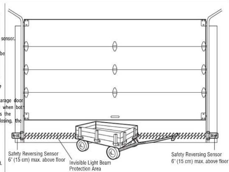
- Correctly connect and align the safety reversing sensor. This required safety device MUST NOT disabled.
• Install the safety reversing sensor so beam is NO HIGHER than 6" (15 cm) above garage floor.
IMPORTANT: The safety reversing sensors MUST be connected and aligned correctly before the garage door opener will move in the down direction.
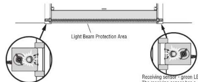
The Protector System® includes two safety reversing sensors which use a light beam to prevent the garage from closing. The sending sensor (amber LED) transmits the beam to the receiving sensor (green LED) when are powered and aligned. The receiving sensor (green LED) has a label on the sensor to identify it as the receiving sensor before it is powered on. If an obstruction breaks the light beam while the door is closing, door will stop, and reverse to the full open position.
When installing the safety reversing sensors, check:
- Sensors are installed INSIDE the garage.
- Sensor lenses are facing each other. IMPORTANT: Do not allow direct sunlight to the receiving sensor (green LED).
- Sensor beam is NO HIGHER than 6" (15 cm) above the floor and the light beam is unobstructed.
• The receiving sensor has a warning sticker on the back.
text_image
sensor. be garage door when bot is the Closing, the Safety Reversing Sensor 6' (15 cm) max. above floor Invisible Light Beam Protection Area Safety Reversing Sensor 6' (15 cm) max. above floorInstall the Protector System®
1 Install the Safety Reversing Sensors
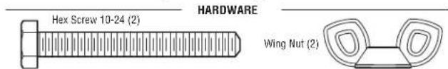
text_image
Hex Screw 10-24 (2) HARDWARE Wing Nut (2)The safety reversing sensors are designed to clip onto the door track with the provided sensor brackets. door track will not support the sensor bracket a wall installation is recommended. The sensor beam should NO HIGHER than 6" (15 cm) above the floor.
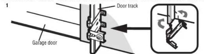
DOORTRACKINSTALLATION
- Slide the curved arms of the sensor bracket around the edge of the door track. Snap into place so sensor bracket is flush against the track.
- Slide the hex screw through the sensor.
- Attach the sensor to the bracket with the wing nut. Make sure the lens is not obstructed by the br. Repeat the steps with the other sensor on the opposite door track. Both lenses must face each other.
text_image
1 Garage door Door track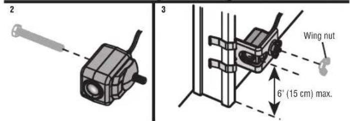
text_image
2 3 Wing nut 6" (15 cm) max.WALL INSTALLATION
Make sure the brackets on each side are clear of the door track and have the same amount of clearance so sensors will align correctly. If additional clearance is needed, use extension brackets 041A5281-1 (not provider or wood blocks.
-
Attach the sensor bracket against the wall with two lag screws (not provided).
-
tSlide the hex screw through the sensor.
-
Attach the sensor to the bracket with the wing nut. Make sure the lens is not obstructed by the bracket.
Repeat the steps with the other sensor on the opposite side of the garage door. Both lenses must face each
other. hat the
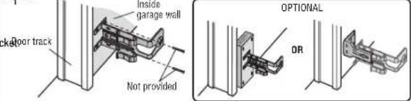
text_image
inside garage wall floor track Not provided OPTIONAL OR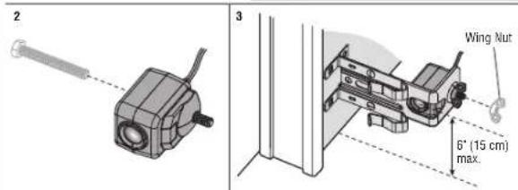
text_image
2 3 Wing Nut 6' (15 cm) max.Install the Protector System®
FLOORINSTALLATION
- Measure the position of both sensor brackets so they will be the same distance from the wall and unobstructed.
- Attach the bracket to the floor with concrete anchors (not provided).
- Slide the hex screw through the sensor.
- Attach the sensor to the bracket with the wing nut. Make sure the lens is not obstructed by the bra
Repeat the steps with the other sensor on the opposite side of the garage door. Both lenses must face other.
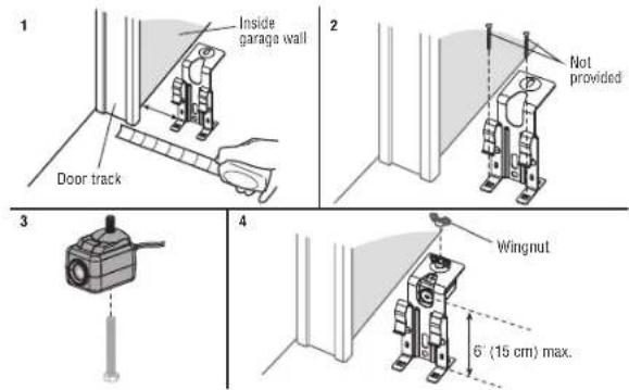
text_image
1 Inside garaga wall 2 Not provided Door track 3 4 Wingnut 6' (15 cm) max.2 Wire the Safety Reversing Sensors
PRE-WIRED INSTALLATIONS: If your garage already has wires installed for the safety reversing sensors, see
page 28
OPTION A - INSTALLATION WITHOUT PRE-WIRING
- Run the wire from both sensors to the garage door opener. Attach with staples, but DO NOT puncture the socket. wire.
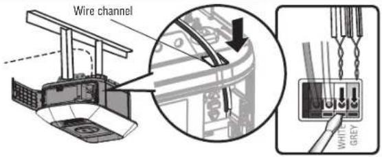
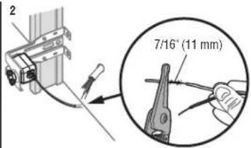
a) Separate the sensor wires and strip insulation from each end. Twist the two white wires together. Then twist the two white/black wires together. - Using a screwdriver, push in the terminal tabs, and insert the white wires into the white terminal. Insert the white/black wires into the grey terminal.
text_image
1 Staple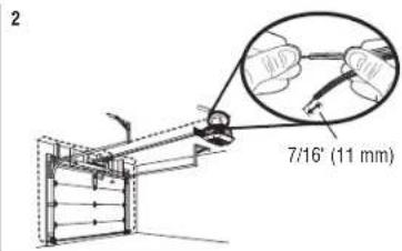
text_image
2 7/16" (11 mm)3
text_image
Wire channel WHITE GREYInstall the Protector System®
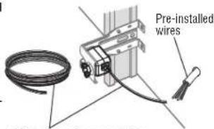
OPTION B- PRE-WIRED INSTALLATION
- Cut the sensor wires, making sure there is enough wire to reach the pre-installed wires from the wall.
- Separate the sensor wires and strip insulation from each end. Choose two of the pre-installed wires and strip insulation from each end. Choose the same color pre-installed wires for each sensor.
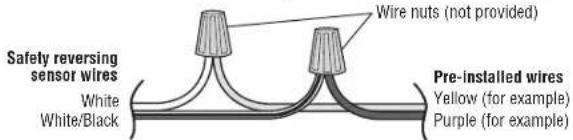
- Connect the pre-installed wires to the sensor wires with wire nuts making sure the colors correspond for each sensor.
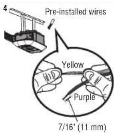
- At the garage door opener, strip the end of the wires previously connected to the sensors. Twist the like-colored wires together.
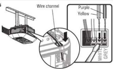
- Using a screwdriver, push in the terminal tabs, and insert the wire color connected to the sensor's white wire into the white terminal. Insert the other wire color connected to the sensor's white/black wire into the grey terminal.
1
text_image
Pre-installed wiresSafety reversing sensor wires
text_image
2 7/16" (11 mm)3
text_image
Safety reversing sensor wires White White/Black Wire nuts (not provided) Pre-installed wires Yellow (for example) Purple (for example)4
text_image
Pre-installed wires Yellow Purple 7/16" (11 mm)5
text_image
Wire channel Purple Yellow WHITE GREYPower
1 Connect Power

WARNING
To prevent possible SERIOUS INJURY or DEATH from electrocution or fire:
- Be sure power is NOT connected to the opener, and disconnect power to circuit BEFORE removing cover to establish permanent wiring connection.
- Garage door installation and wiring MUST be in compliance with ALL local electrical and building codes.
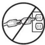
- NEVER use an extension cord, 2-wire adapter, or change plug in ANY way to make it fit outlet. the opener is grounded.
To avoid installation difficulties, do not activate the garage door opener at this time.
To reduce the risk of electric shock, your garage door opener has a grounding type plug with a third pin. This plug will only fit into a grounding type outlet. If the plug doesn't fit into your outlet, contact electrician to install the proper outlet.
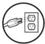
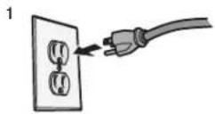
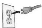
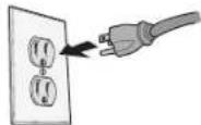
THERE ARE TWO OPTIONS FOR CONNECTING POWER:
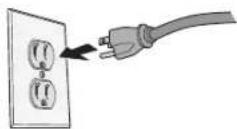
OPTION A - TYPICAL WIRING
- Plug in the garage door opener into a grounded outlet.
- DO NOT run garage door opener at this time.
TYPICAL WIRING
OPTION B - PERMANENT WIRING
If permanent wiring is required by your local code, refer to the following procedure. To make a permanent connection through the 7/8" hole in the top of the motor unit (according to local code):
- Remove the motor unit cover screws and set the cover aside.
- Remove the attached 3-prong cord.
- Connect the black (line) wire to the screw on the brass terminal; the white (neutral) wire to the screw on silver terminal; and the ground wire to the green ground screw. The opener must be grounded.
- Reinstall the cover.
PERMANENT WIRING
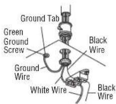
text_image
Ground Tab Green Ground Screw Black Wire Ground Wire White Wire Black WirePower
2 Align the Safety Reversing Sensors
IMPORTANT: The safety reversing sensors MUST be connected and aligned correctly before the garage door opener will move in the down direction.
When the garage door opener has power, check the safety reversing sensors. If the sensors are aligned wired correctly, both LEDs will glow steadily.
text_image
Light Beam Protection Area Receiving sensor - green LE The receiving sensor has aSending sensor - amber LED
Receiving sensor - green LED
The receiving sensor has a sticker on the back.
To align the safety reversing sensors:
- Loosen the wing nuts.
- Adjust the sensors up or down until both LEDs glow steady indicating alignment.
- Tighten the wing nut to secure the sensor.
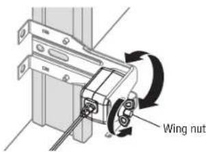
text_image
Wing nutSAFETY SENSORTROUBLESHOOTING
If either of the sensor LEDs are off, there is no power to the sensor:
- Check that you have power to the garage door opener.
- Check the sensor wire is not shorted or broken.
- Check that the sensors are wired correctly; white wires to white terminal and white/black wires to grey terminal.
If the green receiving sensor LED is blinking, the sensors are obstructed or misaligned:
- Check for obstructions in the sensor light beam.
- Align the sensors.
- If the receiving sensor (green LED) faces direct sunlight, switch the receiving sensor with the sending sensor and repeat 1 Install the Safety Reversing Sensors page 26 to assure proper operation.
3 Ensure the Control Panel is Wired Correctly
If the control panel has been installed and wired correctly, the command LED behind the push bar will blink.
Adjustments
1 - Program the Travel


WARNING
Without a properly installed safety reversal system, persons (particularly small children) could be SERIOUSLY INJURED or KILLED by a closing garage door.
- Incorrect adjustment of garage door travel limits will interfere with proper operation of safety rev system.
- After ANY adjustments are made, the safety reversal system MUST be tested. Door MUST reverse contact with 1-1/2" (3.8 cm) high object (or 2x4 laid flat) on floor.
Note: While programming the travel, the UP and DOWN buttons can be used to move the door as needed. During the Automatic Force Setup, the door will automatically open and close.
1 Press and hold the Adjustment Button until the UP Button begins to flash and/or a beep is heard. The Safety Reversing Sensors will be disconnected of process.
2 Press and hold the UP Button until
the door is in the desired UP position.
3 Once the door is in the desired UP position press and release the Adjustment Button. The garage door opener lights will flash twice and the DOWN Button will begin to flas
4 Press and hold the DOWN button until the
door is in the desired DOWN position.
5 Once the door is in the desired DOWN position press and release the Adjustment Button. The garage door opener lights will aflash twice. Program
the Travel is now complete. If the garage door opener lights flash 5 times, then programming has timed out and the Travel Limits have not been set. Please restart the Program the Travel process.
2 - Automatic Force Set Up
Once both the up and down positions have been manually set, the Safety Reversing Sensors will reconnect a become operational. Then, the opener will enter a force-sensing operation by automatically moving the door open and close. The garage door opener will sound an audible and visual alert before automatically opening and closing the door. The garage door opener will beep three times, confirming that the Automatic Force Set completed successfully. Adjustment is complete.
If you hear one long beep after the door attempts to move, then the Automatic Force Set Up has not compl successfully. Please start over at step 1 of Program the Travel.
NOTE: If the travel/force setup process is not completed successfully any attempt to activate the opener from a remote/keyless entry or wall control will not work and the opener will flash the work lights 2 times.
Adjustments
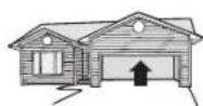
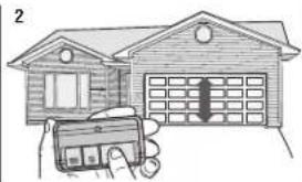
3 - Test the Safety Reversal System
WARNING
Without a properly installed safety reversal system, persons (particularly small children) could be SERIOUSLY INJURED or KILLED by a closing garage door.
• Safety reversal system MUST be tested every month.
- After ANY adjustments are made, the safety reversal system MUST be tested. Door MUST reverse on contact with 1-1/2" (3.8 cm) high object (or 2x4 laid flat) on the floor.
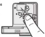
1 With the door fully open, place a 1-1/2 inch (3.8 cm) board (or a 2x4 laid flat) on the floor, centered the garage door.
2 Press the remote control push button to close the door. The door MUST reverse when it makes contact with the board.
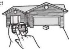
natural_image
Hand holding a car with a door frame inside a house (no text or symbols visible)If the door stops but does not reverse:
1. Repeat Program the Travel (see Adjustment Step 1);
2. Repeat the Safety Reversal test.
If the test continues to fail, call a trained door systems technician.
4 - Test the Protector System®
WARNING
Without a properly installed safety reversing sensor, persons (particularly small children) could be SERIOUSLY INJURED or KILLED by a closing garage door.
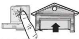
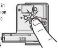
1 Open the door. Place an obstruction in the path of the door.
2 Press the remote control push button to close the door. The door will not move more than an inch (2.5 cm).
The garage door opener will not close from a remote control if the LED in either safety reversing sensor is off (alerting you to the fact that the sensor is misaligned or obstructed).
If the garage door opener closes the door when the safety reversing sensor is obstructed (and the sensors are no more than 6 inches [15 cm] above the floor), call for a trained door systems technician.
Battery Backup\*
1 Install the Battery

WARNING
To reduce the risk of FIRE or INJURY to persons:
- Disconnect ALL electric and battery power BEFORE performing ANY service or maintenance.
• Use ONLY LiftMaster part # 485LM for replacement battery. - DO NOT dispose of battery in fire. Battery may explode. Check with local codes for disposal instructions.

CAUTION
ALWAYS wear protective gloves and eye protection when changing the battery or working around the battery compartment.
The automatic garage door lock will unlock when the garage door is opened, and will remain disabled power is restored.*
- Unplug the garage door opener.
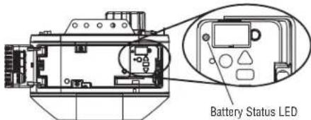
- Open the control door panel.
- Partially insert the battery into the battery compartment with the terminals as shown.
-
Connect red (+) and black (-) wires from the garage door opener to the corresponding terminals on the battery.
-
Fully insert the battery and close the control door panel.
Battery Status LED
text_image
Diagram showing a device connected to a control panel, with magnified views highlighting internal components.* If applicable.
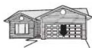
2 Test the Battery
Depending on the power level, the battery may need to charge before performing the test. The garage door opener must be unplugged to test the battery.
- Unplug the garage door opener. The battery status LED will either glow solid orange indicating opener is operating on battery power or will flash indicating low battery power. NOTE: Make sure the garage door opener is unplugged.
- Open and close the door using the remote control or control panel. NOTE: The garage door opener may run slower if the battery is not fully charged. The battery will take 24 hours to fully charge.
- Open and close the door using the remote control or control panel. While the motor is on, the battery status LED will either glow solid orange indicating opener is operating on battery power or will flash indicating low battery power. NOTE: The garage door opener may run slower if the battery is not fully charged.
- Plug in the garage door opener. Verify the battery status LED is flashing green, indicating the battery is charging.
•
natural_image
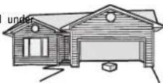
Illustration of a house with a garage and a car, no text or symbols present3
3 Charge the Battery
The battery charges when the garage door opener is plugged into a 120 Vac electrical outlet that has power requires 24 hours to fully charge. A fully charged battery supplies 12 Vdc to the garage door opener for up 24 hours of normal operation during an electrical power outage. After the electrical power has been restored, the battery will recharge within 24 hours. The battery will last approximately 1 to 2 years with normal usage. NOTE: When the garage door opener is in battery backup mode the garage door opener lights, Timer-to-Close, remote close, and camera features are unavailable.
In battery backup mode, the Automatic Garage Door Lock will unlock when the garage door is opened, and I remain disabled until power is restored.*
* If applicable.
Battery Backup\*
Battery Status LED
GREEN LED:
All systems are normal.
• A solid green LED light indicates the battery is fully charged.
- A flashing green LED indicates the battery is being charged.
ORANGE LED:
The garage door opener has lost power and is in battery backup mode.
- Solid orange LED while the motor is on, indicates the garage door opener is operating on battery power.
- A flashing orange LED while the motor is on, indicates the battery is low.
• The opener beeps every 2 seconds while operating on battery power.
RED LED:
The battery needs to be replaced.
- A solid red LED with beep indicates the battery will no longer hold a charge. Purchase a replacement battery to allow your system to operate during a power outage.
text_image
Battery Status LED* If applicable.
Operation
IMPORTANT SAFETY INSTRUCTIONS
WARNING
To reduce the risk of SEVERE INJURY or DEATH:
- READ AND FOLLOW ALL WARNINGS AND INSTRUCTIONS.
- ALWAYS keep remote controls out of reach of children. NEVER permit children to operate or play garage control panel push buttons or remote controls.
- ONLY activate garage door when it can be seen clearly, it is properly adjusted, and there are no obstructions to door travel.
- ALWAYS keep garage door in sight and away from people and objects until completely closed. NO SHOULD CROSS THE PATH OF THE MOVING DOOR.
- NO ONE SHOULD GO UNDER A STOPPED, PARTIALLY OPENED DOOR.
- If possible, use emergency release handle to disengage trolley ONLY when garage door is CLOSED caution when using this release with the door open. Weak or broken springs or unbalanced door result in an open door falling rapidly and/or unexpectedly and increasing the risk of SEVERE INJ DEATH.
- NEVER use emergency release handle unless garage doorway is clear of persons and obstructions.
- NEVER use handle to pull garage door open or closed. If rope knot becomes untied, you could fa
- After ANY adjustments are made, the safety reversal system MUST be tested.
- Safety reversal system MUST be tested every month. Garage door MUST reverse on contact with 1-1/2" with (3.8 cm) high object (or a 2x4 laid flat) on the floor. Failure to adjust the garage door opener properly increases the risk of SEVERE INJURY or DEATH.
- ALWAYS KEEP GARAGE DOOR PROPERLY BALANCED (see page 4). An improperly balanced door may NOT reverse when required and could result in SEVERE INJURY or DEATH.
ONEALL repairs to cables, spring assemblies and other hardware, ALL of which are under EXTREME tension, MUST be made by a trained door systems technician. - To avoid interference with the proper operation of the garage door opener when using a welder in the Use garage, unplug garage door opener before operating welder.
could This operator system is equipped with an unattended operation feature. The door could move unexpectedly. NO ONE SHOULD CROSS THE PATH OF THE MOVING DOOR. - DO NOT install on a one-piece door if using devices or features providing unattended close. Unattended devices and features are to be used ONLY with sectional doors.
17. SAVE THESE INSTRUCTIONS.
Operation
Features
Your garage door opener is equipped with features to provide you with greater control over your garage operation.
ALERT2CLOSE
The Alert2Close feature provides a visual and an audible alert that an unattended door is closing. TIMER-TO-CLOSE(TTC)*
The TTC feature automatically closes the door after a specified time period that can be adjusted using enabled control panel (Models 881LMW or 880LMW). Prior to and during the door closing the garage opener lights will flash and the garage door opener will beep.
MYQ
myQ® allows you to control your garage door opener from your mobile device from anywhere. myQ® te uses a 900 Mhz signal to provide two way communication between the garage door opener and myQ® accessories.
The garage door opener has an internal gateway that allows the garage door opener to communicate with a home Wi-Fi® network and access your myQ® account.
THE PROTECTORSYSTEM(SAFETY REVERSING SENSORS)
When properly connected and aligned, the safety reversing sensors will detect an obstruction in the pat infrared beam. If an obstruction breaks the infrared beam while the door is closing, the door will stop reverse to full open position. If the door is fully open, and the safety reversing sensors are not installed misaligned, the door will not close from a remote control. However, you can close the door if you hold button on the control panel or keyless entry until the door is fully closed. The safety reversing sensors affect the opening cycle. For more information see page 25.
LIGHTS
The garage door opener Integrated LED lights will turn on when the opener is initially plugged in; power is restored after interruption, or when the garage door opener is activated. The lights will turn off automatically after 4-1/2 minutes.
USING YOURGARAGE DOOROPENER
When the door is closed and the garage door opener is activated the door will open. If the door makes con with an obstruction while opening, the door will stop, opener beeps and lights flash 5 times. When the door any position other than closed and the garage door opener is activated, the door will close. If the garage dc makes contact with an obstruction while closing, the door will reverse, opener beeps and lights flash 5 times. However, you can close the door if you hold the button on the control panel or keyless entry until the door fully closed.
The safety reversing sensors do not affect the opening cycle. The safety reversing sensor must be connected and aligned correctly before the garage door opener will move in the down direction.
BATTERY BACKUP\*
The battery backup system allows access in and out of your garage, even when the power is out. When the garage door opener is operating on battery power, the garage door opener will run slower, the light will not function, the Battery Status LED will glow solid orange, and a beep will sound approximately every 2 seconds every CAMERA*
Live steam what is happening in your garage with your garage door opener's built-in camera. Just connect your opener to Wi-Fi and set up an account with the AppQFor more information, see page 38.
AUTOMATIC GARAGE DOORLOCK\*
Garage door opener models featuring the Security Shield are compatible with the LiftMaster Automatic Garage Door Lock (Model 841LM). If applicable. to not
Operation
Connect With Your Smartphone
The Wi-Fi Garage Door Opener is compatible with up to 1000000000 accessories. Up to 10 devices can be paired to the Wi-Fi garage door opener's internal gateway. These devices can be controlled with the myQ. These devices include any combination of flyqage door openers, Wi-Fi garage door openers, light controls, myQ gate operators or myCommercial door operators. A LiftMaster Internet Gateway (828LM) can be added if you need to control more than 10 devices using the myUp to 6 devices can be paired to garage door opener itself (controlled by garage door opener through 900MHz). These devices include any combination of myLight controls or a garage door and gate monitor.
YOU WILL NEED:
• Wi-Fi enabled smartphone, tablet or laptop
- Broadband Internet Connection
• Wi-Fi signal in the garage (2.4 GHz, 802.11b/g/n required), see page 3
- Password for your home network (router's main account, not guest network)
- myQ* serial number located on the garage door opener
DOWNLOAD THEMYQ®APPTO SET UPAN ACCOUNT AND CONNECT
Open and close your door, get alerts and set schedules from anywhere. Connected smart garage door also receive software updates to ensure the opener has the latest operational features. The garage door opener must run through a complete cycle before it will activate or refining.
- Download the myQ® App.
- Set up an account and connect.
If you already have the myApp installed:
- Check that your mobile device has the latest software.
- Download the latest version of the myApp.

GET IT ON Google Play

Download on the App Store
For more information on connecting your garage door opener, visit support.LiftMaster.com.
Google Play and the Google Play logo are trademarks of Google LLC.
App Store and the Apple and App Store logos are trademarks of Apple Inc.
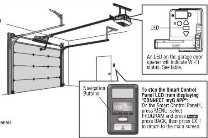
text_image
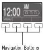
LED An LED on the garage door opener will indicate Wi-Fi status. See table. Navigation Buttons To stop the Smart Control Panel LCD from displaying "CONNECT myQ APP". On the Smart Control Panel®, press MENU, select PROGRAM and press press BACK, then press EXIT to return to the main screen.| Wi-Fi Status | |
| LED Definition | |
| Blue Off - Wi- | Fi ^® is not turned on.Blinking - Garage door opener is in Wi-Fi ^® learn mode.Solid - Mobile device connected to the garage door opener. |
| Blue and Green | Blinking - Attempting to connect to router. |
| Green Blinking | - Attempting to connect to the Internet server.Solid - Wi-Fi ^® has been set up and garage door opener is connected to the |
NOTES:
myQ® App control WILL NOT work if the garage door opener is operating on battery power. To erase the Wi-Fi settings, see page 41.
Operation
Set Up the Camera - Models 87504-267, 84504R, and 84505R
- Download the myQ* app and setup your account if you haven't already, see page 37.
- Follow the instructions in the app to setup and use the camera.
The camera powers up when it is opened and powers down when closed.
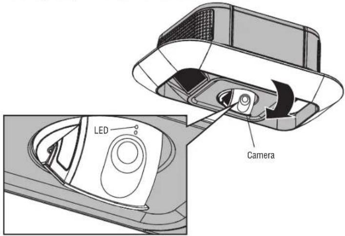
text_image
LED Camera| Camera Status | |
| LED Definition | |
| Flashing Blue Camera | is attempting to connect to the mobile device. |
| Solid Blue Camera is connected to the mobile device. | |
| Flashing Blue and Green | Camera is attempting to connect to the router. |
| Flashing Green Camera | is connected to the router and attempting to connect to myQ *server. |
| Solid Green | Camera is connected and working normally. |
| Solid White | Camera is powering up. |
| Flashing Red | Camera is overheating. |
| Flashing Purple | Camera firmware is updating. |
Operation
Using the Control Panel
SYNCHRONIZETHE CONTROL PANEL
To synchronize the control panel to the garage door opener, press the push bar until the garage door activates (it may take up to 3 presses). Test the control panel by pressing the push bar, each press of push bar will activate the garage door opener.
NOTE: Your control panel may look different than the illustrations.
Up to 2 Smart Control Panels ^9 or 4 of any other Security+ 2.0 control panels can be connected to the door opener.
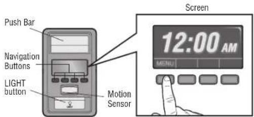
text_image
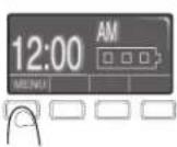
Push Bar Navigation Buttons LIGHT button Motion Sensor Screen 12:00 AM MENUPUSH BAR
Press the push bar to open or close the door.
NAVIGATION BUTTONS
Use the navigation buttons to make selections and program features.
LIGHT BUTTON
Press the LIGHT button to turn the garage door opener lights on or off. When the lights are turned on they will stay on until the LIGHT button is pressed again, or until the garage door opener is activated. Once the garage door opener is activated the lights will turn off after the specified period of time (the factory setting is 4-1/2 minutes). The LIGHT button will not control the lights when the door is in motion.
SCREEN\*
The screen will display the time and temperature until the menu button is pressed, and then it will display the menu options. If there is a problem with the garage door opener the screen will display the Diagnostic Code. Refer to the Troubleshooting section.
The following features are accessible through the screen using the navigation buttons:
LEARN A DEVICE
Program compatible remote controls, wireless keyless entries, Wi-Fi garage door openers, or myQ® accessories to the garage door opener.
LOCK
The LOCK feature is designed to prevent activation of the garage door opener from remote controls while still allowing activation from the control panel and keyless entry. This feature is useful for added peace of mind when the home is empty (i.e. vacation).
TIMER-TO-CLOSE (TTC)\*
DO NOT enable TTC if operating a one-piece door. TTC is to be used ONLY with sectional doors. Factory del is set to off. TTC can be set to automatically close your garage door from the fully open position after a sp period of time (1, 5, 10 minute intervals or a custom setting up to 99 minutes). The garage door opener will send and the lights will Flash before closing the door. The screen on the control panel can display the status of the TTC. TTC WILL NOT work if the garage door opener is operating by battery power or if the safety revers sensors are misaligned. This feature is NOT intended to be the primary method of closing the door. A keyless entry should be installed in the event of an accidental lock out when using this feature.
AUTOMATIC LIGHT
Motion Sensor \*
Factory default is set to on. This feature automatically turns on the garage door opener lights when motion is sensed. The lights will come on for the set period of time, then shut off. If using the garage door opener light a work light disable the motion sensor, otherwise the light will turn off automatically if you are beyond the r of the sensor.
MAINTENANCEALERT (MAS)
This feature assists the homeowner in ensuring the garage door opener system stays in good working condition. When the garage door opener needs to be serviced (approximately 4500 garage door opener cycles) the command (yellow) and service (red) LEDs will begin to alternately flash back and forth. The factory setting for the MAS feature is off and can be activated at time of installation. Contact your installing dealer for service. *If applicable
Operation
Using the Smart Control Panel®\*
SETUP
The features on the control panel can be programmed through a series of menus on the screen and the navigation buttons. Refer to the descriptions below.
SCREEN
The main screen displays the time, temperature, and current battery charge (if applicable).
FEATURES
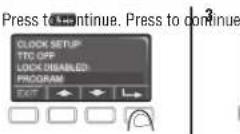
Press the navigation button below "MENU" to view the Features menu.
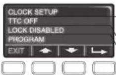
Set the time, choose 12 or 24 hour clock and show/hide clock. For sectional doors ONLY. Set the Timer-to-Close feature off/on and set the time interval before door closes. NOTE: DO NOT enable TTC if operating a one-piece door. TTC is to be used ONLY with sectional doors. Enable/disable lock.
Set up Wi-Fi ^* , add remote controls, myQ ^ devices, an extra remote button to control your garage door opener lights, or a keyless entry.
* The garage door opener must run through a complete cycle before it will activate Wi-Fi® programming.
*If applicable
SETTINGS
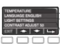
Press the navigation button below the down arrow till you see TEMPERATURE to view the Settings menu.
text_image
TEMPERATURE LANGUAGE ENGLISH LIGHT SETTINGS CONTRAST ADJUST 50 EXITDisplay the temperature in Fahrenheit or Celsius and show/hide the temperature.
Select a language.
Set duration for garage door opener light to stay on after operation, selectable range of 1-1/2 to 4-1/2 minutes. Turn the Motion sensor off/on, and turn the entry light feature off/on.
Adjust the contrast of the screen.
SERVICE
Press and hold the LIGHT button, then press the second navigation button to view the Service menu.
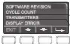
Displays software version information.
Turn the Maintenance Alert (MAS) on/off.
Displays the number of remote controls, myQ ^® devices, control panels, and keyless entries currently programmed to operate the garage door opener.
Displays any errors that have occurred.
Remote Control
Your remote control has been programmed at the factory to operate with your garage door opener.
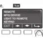
TO ADD, REPROGRAM, OR CHANGE A REMOTE CONTROL/KEYLESS ENT USING THE CONTROL PANEL
- Press the navigation button below "MENU" to view the Features menu.
- Use the navigation buttons to scroll to "PROGRAM".
- Select "REMOTE" or "KEYPAD" to program from the program menu.
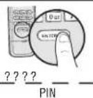
- Remote Control: Press the button on the remote control that you wish to operate your garage door. Keyless Entry: Enter a 4-digit personal identification number (PIN) of your choice on the keyless entry keypad. Then press the ENTER button.
The garage door opener lights will flash (or two clicks will be heard) when the code has been programmed. Repeat the steps above for programming additional remote controls or keyless entry devices. If programming is unsuccessful, program the remote using the learn button.
Operation
1
2
b
4

OR
TO ADD, REPROGRAM, OR CHANGE A REMOTE CONTROL USING BUTTON
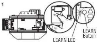
- Press and release the LEARN Button on the garage door opener.
- Press and hold the button on the remote control that you wish to use. Release the button when the garage door opener lights blink or two clicks are heard.
1
text_image
LEARN LED LEARN Button2
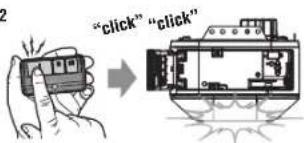
text_image
"click" "click"To Erase the Memory
ERASEALL REMOTECONTROLS AND KEYLESSENTRIES
- Press and hold the LEARN button on garage door opener until the learn LED goes out (approximately 6 seconds).
- Immediately press and hold the LEARN button again until the learn LED goes out. All codes are now erased. Reprogram any accessory you wish to use.
ERASETHE CAMERA SETTINGS
- Press and hold black adjustment button on the garage door opener until 3 beeps are heard (approximate 6 seconds). The LED light will turn off, then flash red.
You will need to setup both the garage door opener and camera again after resetting it.
THE LEARN
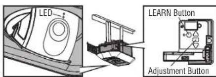
text_image
LED LEARN Button Adjustment ButtonOperation
To Open the Door Manually
WARNING
To prevent possible SERIOUS INJURY or DEATH from a falling garage door:
- If possible, use emergency release handle to disengage trolley ONLY when garage door is CLOSED. Weak or broken springs or unbalanced door could result in an open door falling rapidly and/or unexpectedly.
- NEVER use emergency release handle unless garage doorway is clear of persons and obstructions.
- NEVER use handle to pull door open or closed. If rope knot becomes untied, you could fall.
-
The door should be fully closed if possible.
-
Pull down on the emergency release handle.
The lockout feature prevents the trolley from reconnecting automatically.
1. Pull the emergency release handle down and back (toward the opener). The door can then be raised and lowered manually as often as necessary.
2. To disengage the lockout feature, pull the handle straight down. The trolley will reconnect on the next UP or DOWN operation, either manually or by using the control panel or remote control.
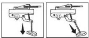
TO MANUALLY DISENGAGE AUTOMATIC GARAGEDOORLOCK (MODEL 841LM)\*
- The door should be fully closed if possible.
- Disengage the automatic garage door lock by sliding the manual release to the open position.
- Pull the emergency release handle down and back (toward the garage door opener). The garage door can then be raised and lowered manually as necessary.
- To reconnect the trolley, pull the emergency release handle straight down. The trolley will reconnect on the next UP or DOWN operation.
NOTE: The automatic garage door lock will re-engage when garage door opener operation resumes.
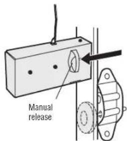
text_image
Manual release* If applicable.
Maintenance
Maintenance Schedule
EVERY MONTH
- Manually operate door. If it is unbalanced or binding, call a trained door systems technician.
- Check to be sure door opens and closes fully. Adjust if necessary, see page 31.
- Test the safety reversal system. Adjust if necessary, see page 32.
EVERY YEAR
- Oil door rollers, bearings and hinges. The garage door opener does not require additional lubrication not grease the door tracks.
- Test the battery and consider replacing the battery to ensure the garage door opener will operate d an electrical power outage, see page 33 to test the battery backup.
EVERY TWO TO THREEYEARS
- Use a rag to wipe away the existing grease from the garage door opener rail. Reapply a small layer lithium grease to the top and underside of the rail surface where the trolley slides.
NOTICE: This device complies with part 15 of the FCC rules and Innovation, Science and Economic Development Canada license-exempt RSSs. Operation is subject to the following two conditions: (1) this device may not cause harmful interference, and (2) this device must accept any interference received, including interference that may cause undesired operation. Any changes or modifications not expressly approved by the party responsible for compliance could void the user's authority to operate the equipment.
This device has been tested and found to comply with the limits for a Class B digital device, pursuant to part 15 of the FCC rules and Industry Canada ICES standard. These limits are designed to provide reasonable protection against harmful interference in a residential installation. This equipment generates, uses and can radiate radio frequency energy and, if not installed and used in accordance with the instructions, may cause harmful interference to radio communications. However, there is no guarantee that interference will not occur in a particular installation. If this equipment does cause harmful interference to radio or television reception, which can be determined by turning the equipment off and on, the user is encouraged to try to correct the interference by one or more of the following measures:
• Reorient or relocate the receiving antenna.
- Increase the separation between the equipment and receiver.
- Connect the equipment into an outlet on a circuit different from that to which the receiver is connected.
- Consult the dealer or an experienced radio/TV technician for help.
The Remote Control Battery
WARNING
To prevent possible SERIOUS INJURY or DEATH:
• NEVER allow small children near batteries.
Do If battery is swallowed, immediately notify doctor.
To reduce risk of fire, explosion or chemical burn:
Replace ONLY with 3V CR2032 coin batteries.
• DO NOT recharge, disassemble, heat above 212°F (100°C) or incinerate.
of white
To replace the battery, pry open the case in the middle, then at each side with the visor clip. Insert replacement battery positive side up (+). Replace the batteries with only 3V CR2032 coin cell batteries. Dispose of old batteries properly.
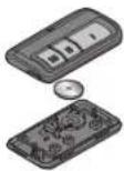
Troubleshooting
DiagnosticChart
Your garage door opener is programmed with self-diagnostic capabilities. The UP and DOWN arrows on the garage door opener flash the diagnostic codes.
| DIAGNOSTIC CODE SYMPTOM SOLUTION | ||||
| Up Arrow Flash(es) | Down Arrow Flash(es) | |||
| 1 | 1 | The garage door opener will not close. | Safety reversing sensors are not installed, connected, or wires may be cut. Inspect sensor wires for a disconnected or cut wire. | |
| 1 | 2 | The garage door opener will not close. | There is a short or reversed wire for the safety reversing sensors. Inspect safety sensor wire at all staple and connection points, replace wire or correct as needed. | |
| 1 | 3 | The control panel will not function. | The wires for the control panel are shorted or the control panel is faulty. Inspect control panel wires at all staple and connection points, replace wire or correct as needed. | |
| 1 | 4 | The garage door opener will not close. | Safety reversing sensors are misaligned or were momentarily obstructed. Realign both sensors until both LEDs are glowing steady. Make sure nothing is hanging or mounted on the door that would interrupt the sensor's pi while closing. | |
| 1 | 5 | Door moves 6-8" (15-20 cm) stops or reverses. | Manually open and close the door. Check for binding or obstructions, such as a broken spring or door lock, correct as needed. Check wiring connections at travel module and at the logic board. Replace travel module if necessary. | |
| No movement, only a single click. | Manually open and close the door. Check for binding or obstructions, such as a broken spring or door lock, correct as needed. Replace logic board if necessary. | |||
| Opener hums for 1-2 seconds no movement. | Manually open and close the door. Check for binding or obstructions, such as a broken spring or door lock, correct as needed. Replace motor if necessary. | |||
| 1 | 6 | Door coasts after it has come to a complete stop. | Program travel to coasting position or have door balanced by a trained door systems technician. | |
| 2 | 1-5 | No movement, or sound. | Replace logic board. | |
| 3 | 2 | Unable to set the travel or retain position. | Check travel module for proper assembly, replace if necessary. | |
| 3 | 3 | The battery status LED is constantly flashing green. | Battery backup charging circuit error, replace the logic board. | |
Troubleshooting
| DIAGNOSTIC CODE SYMPTOM SOLUTION | |||
| Up Arrow Flash(es) | Down Arrow Flash(es) | ||
| 4 | 1-4 | Door is moving, stops or reverses. Opener beeps and lights flash. | Manually open and close the door. Check for binding or obstructions, such as a broken spring or door lock, correct as needed. If the door is binding or sticking, contact a trained door systems technician. If door is not binding or sticking attempt to reprogram travel (refer to 32). |
| 4 | 5 | Opener runs approximately 6-8" (15-20 cm), stops and reverses. | Communication error to travel module. Check travel module connections, replace travel module if necessary. |
| 4 | 6 | The garage door opener will not close. | Safety reversing sensors are misaligned or were momentarily obstructed. Realign both sensors to ensure both LEDs are steady and not flickering. Make sure nothing is hanging or mounted on the door that would interrupt the sensor's path while closing. |
The garage door opener will NOT enter Wi-Fi® learn mode:
- After the initial installation of the garage door opener, the garage door opener must complete a full Open lock wiring on both Integrated LED Light Modules to connector. If loose, then reconnect. If the lights do r (open and closed) before the Wi-Fi® learn mode can be activated. turn on, a new Integrated LED Light Module may be needed. Connect customer service or certified door
- If there has been a recent power outage, the garage door opener must complete a full cycle before professional to determine if a new Integrated LED Light Module is needed. Wi-Fi® LEARN MODE can be activated.
Cannot connect garage door opener to home Wi-Fi® network:
- Ensure the myQ ^ Serial number was entered correctly and try again. The myQ ^ characters are between A-F and 0-9 only. My
- Weak Wi-Fi® signal in the garage. Ensure the Wi-Fi® signal is reaching the garage. Visit support.chamberlaingroup.com for more information.
LEDs are not working:
Chycode wiring on both Integrated LED Light Modules to connector. If loose, then reconnect. If the lights do r turn on, a new Integrated LED Light Module may be needed. Connect customer service or certified door
professional to determine if a new Integrated LED Light Module is needed.
My neighbor's remote control opens my garage door:
Erase the memory from your garage door opener and reprogram the remote control(s).
My door will not close:
The safety reversing sensor must be connected and aligned correctly before the garage door opener will move. Move your router closer to the garage door opener to minimize interference from walls and other objects in the down direction. - Buy a Wi-Fi ^® range extender.
- Check for binding or obstructions anywhere along the track to garage floor.
- The safety reversing sensor must be connected and aligned correctly before the garage door opener wild app instructions to set up the camera. move in the down direction. To troubleshoot the optional automatic garage door lock model 841LM, see the instructions provided with
- Verify the safety reversing sensors are properly installed, aligned and free of any obstructions.
- If the receiving sensor (green LED) faces direct sunlight, switch the receiving sensor with the sending sensor so the receiving sensor is not in direct sunlight.
My camera won't connect to the router:
Accessories
878MAX MAX Wireless Keyless Entry:
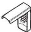
For use outside of the home to enable access to the garage using a 4-digit PIN. Works with ALL LiftMaster openers from 1993-present.
893MAX 3-Button MAX Remote Control:
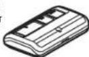
Compatible with LiftMaster garage door openers manufactured since 1993. Includes visor clip.
880LMW Smart Control Panel:
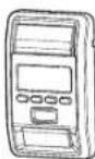
Displays temperature, time and system diagnostics; includes a push bar to open and close the door and a lock feature for extra security. Security+ 2.0 and Wi-Fi compatible.
819LMB myQ

* Home Bridge:
Add Apple HomeKit™ compatibility to your myQ enabled garage door opener. Use Siwi open, close and check the status of your door.
Apple is a trademark of Apple Inc., registered in the U.S. and other countries. HomoKit is a trademark of Apple Inc.
891LM
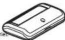
Compatible with LiftMaster garage door openers manufactured since 1993. Includes visor clip.
(1)基因通过控制 通过控制
882LMW Multi-Function Control Panel:
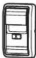
Security+ 2.0 and Wi-Fi compatible.
374UT Mini Universal Remote Control:

The Mini Universal Remote Control can be programme to activate up to two products, such as a garage door opener, my@light controls, gate operator, or commercial door operator.
380UT Universal Remote Control:
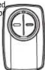
The Universal Remote Control can be programmed to activate up to two products such as a garage door opener, gate operator or commercial door operator.
841LM Automatic Garage Door Lock:
Compatible with 87802. Provides added security by automatically locking garage door travel at the garage door track.
881LMW Motion Detecting Control Panel with Timer-to-Close
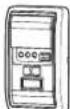
Control:
Multi-function control panel with motion sensor that automatically turns opener lights on when it detects person entering the garage. Security+ 2.0 and Wi-Fi compatible.
886LMW Motion Detecting Control Panel:
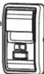
Multi-function control panel with motion sensor that automatically turns opener lights on when it detects a person entering the garage. Security+ 2.0 and Wi-Fi compatible.
Warranty
LiftMaster ^® ("Seller") warrants to the first retail purchaser of this product, for the residence in which this product is originally installed, that it is free from defects in materials and/or workmanship for a specific period of time as defined below (the "Warranty Period"). The warranty period commences from the date of purchase.
| WARRANTY PERIOD | |||||||
| Models Parts Motor Accessories Belt Battery Backup | Integrated LED Camera | ||||||
| 84504R 1 year Lifetime 1 year Lifetime 1 year 1 year 1 year | |||||||
| 84505R 1 year Lifetime 1 year Lifetime N/A 1 year | 1 year | ||||||
| 84602 1 year Lifetime 1 year N/A | 1 year 1 year N/A | ||||||
| 87802 | 5 years | Lifetime | 1 year | Lifetime | 1 year | 5 years | N/A |
| 87504-267 | 5 years | Lifetime | 1 year | Lifetime | 1 year | 5 years | 1 year |
The proper operation of this product is dependent on your compliance with the instructions regarding installation, operation, and maintenance and testing. Failure to comply strictly with those instructions will void this limited warranty in its entirety.
If, during the limited warranty period, this product appears to contain a defect covered by this limited warranty, visit LiftMaster.com, before dismantling this product. You will be advised of disassembly and shipping instructions. Then send the product or component, pre-paid and insured, as directed to our service center for warranty repair. Please include a brief description of the problem and a dated proof-of-purchase receipt with any product returned for warranty repair. Products returned to Seller for warranty repair, which upon receipt by Seller are confirmed to be defective and covered by this limited warranty, will be repaired or replaced (at Seller's sole option) at no cost to you and returned pre-paid. Defective parts will be repaired or replaced with new or factory-rebuilt parts at Seller's sole option. [You are responsible for any costs incurred in removing and/or reinstalling the product or any component].
ALL IMPLIED WARRANTIES FOR THE PRODUCT, INCLUDING BUT NOT LIMITED TO ANY IMPLIED WARRANTIES OF MERCHANTABILITY AND FITNESS FOR A PARTICULAR PURPOSE, ARE LIMITED IN DURATION TO THE APPLICABLE LIMITED WARRANTY PERIOD SET FORTH ABOVE FOR THE RELATED COMPONENT(S), AND NO IMPLIED WARRANTIES WILL EXIST OR APPLY AFTER SUCH PERIOD. Some States and Provinces do not allow limitations on how long an implied warranty lasts, so the above limitation may not apply to you. THIS LIMITED WARRANTY DOES NOT COVER NON-DEFECT DAMAGE, DAMAGE CAUSED BY IMPROPER INSTALLATION, OPERATION OR CARE (INCLUDING, BUT NOT LIMITED TO ABUSE, MISUSE, FAILURE TO PROVIDE REASONABLE AND NECESSARY MAINTENANCE, UNAUTHORIZED REPAIRS OR ANY ALTERATIONS TO THIS PRODUCT), LABOR CHARGES FOR REINSTALLING A REPAIRED OR REPLACED UNIT, REPLACEMENT OF CONSUMABLE ITEMS (E.G., BATTERIES IN REMOTE CONTROL TRANSMITTERS), OR UNITS INSTALLED FOR NON-RESIDENTIAL USE. THIS LIMITED WARRANTY DOES NOT COVER ANY PROBLEMS WITH, OR RELATING TO, THE GARAGE DOOR OR GARAGE DOOR HARDWARE, INCLUDING BUT NOT LIMITED TO THE DOOR SPRINGS, DOOR ROLLERS, DOOR ALIGNMENT OR HINGES. THIS LIMITED WARRANTY ALSO DOES NOT COVER ANY PROBLEMS CAUSED BY INTERFERENCE. UNDER NO CIRCUMSTANCES SHALL SELLER BE LIABLE FOR CONSEQUENTIAL, INCIDENTAL OR SPECIAL DAMAGES ARISING IN CONNECTION WITH USE, OR INABILITY TO USE, THIS PRODUCT. IN NO EVENT SHALL SELLER'S LIABILITY FOR BREACH OF WARRANTY, BREACH OF CONTRACT, NEGLIGENCE OR STRICT LIABILITY EXCEED THE COST OF THE PRODUCT COVERED HEREBY. NO PERSON IS AUTHORIZED TO ASSUME FOR US ANY OTHER LIABILITY IN CONNECTION WITH THE SALE OF THIS PRODUCT.
Some states and provinces do not allow the exclusion or limitation of consequential, incidental or special damages, so the above limitation or exclusion may not apply to you. This limited warranty gives you specific legal rights, and you may also have other rights, which vary from state to state and province to province.
Automatic Garage Door Opener Safety & Maintenance Guide
Garage Door Opener Safety – An Automatic Decision
A garage door is the largest moving object in the home. An improperly adjusted garage door and opener can exert deadly force when the door closes – which could lead to entrapment of children or adults and subsequent injury or death.
Proper installation, operation, maintenance, and testing of the garage door and automatic opener are necessary to provide a safe, trouble-free system. Careless operation or allowing children to play with or use garage door opener controls are also dangerous situations that can lead to tragic results. A few simple precautions can protect your family and friends from potential harm. Please review the safety and maintenance tips in this guide carefully and keep it for reference. Check the operation of your garage door and opener to ensure they function in a safe and trouble-free manner. Be sure to read all Important Safety Information found in your garage door opener's manual as it provides more details and safety considerations than can be supplied with this guide.
Garage Door Openers are Not Toys
Discuss garage door and opener safety with your children. Explain the danger of being trapped under the door.
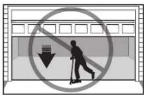
text_image
Prohibition sign with silhouette of person using scooter and downward arrow, enclosed in a building windowStay away from a moving door. The wall-mounted push button
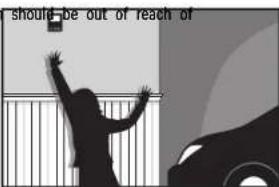
text_image
should be out of reach ofchildren, at least 5 feet from the nearest standing surface and away from all moving parts. Mount and use the button where you can clearly see the closing garage door.
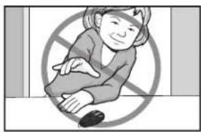
natural_image
Illustration of a person sitting with a crossed-out circle in the background (no text or symbols)Keep transmitters and remote controls out of reach of children. Do not let children play with or use transmitters or other remote control devices.
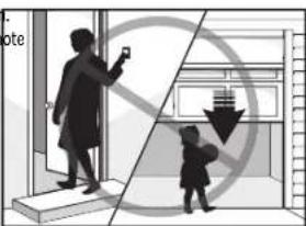
text_image
NoteKeep the door in sight until it completely closes when using the wall-mounted push button or transmitter.
Routine Maintenance Can Prevent Tragedies
Make monthly inspection and testing of your garage door and opener system a part of your regular routine. Review your owner's manual for both the door and door opener. If you don't have the owner's manuals, contact the manufacturer(s) and request a copy for your specific model(s). Look for the opener model number on the back of the power unit.

WARNING – SPRINGS ARE UNDER HIGH TENSION. ONLY QUALIFIED INDIVIDUALS SHOULD ADJUST THEM.
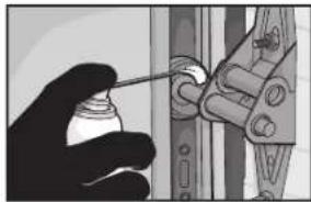
natural_image
Illustration of a hand holding a spray bottle, with a tool interacting with a mechanical component (no text or symbols visible)Visually check the door and installation:
- Starting with the door in the closed position, use the manual disconnect on the opener to disconnect the door.
- Look for signs of wear or damage on hinges, rollers, springs, and door panels.
• These parts may require periodic lubrication. Check the owner's manual for suggested maintenance.
• If any signs of damage are evident, contact a trained door systems technician for assistance. - Verify the photoeye height is no higher than 6" from the garage floor.
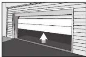
natural_image
Exterior view of a modern garage with a white upward arrow indicating clearance (no text or symbols)Test the door for proper operation:
- Open and close the door manually using handles or suitable gripping points.
• The door should move freely and without difficulty.
• The door should balance and stay partially open 3–4 feet above the floor.
• If you detect any signs of improper operation, contact a trained door systems technician for assistance.
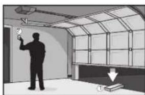
natural_image
Interior view of a room with a person holding a wall-mounted device and a window, no visible text or symbolsTest the opener safety features:
- Reconnect the opener to the door using the manual disconnect and open the door.
- Place a 2x4 board flat in the path of the door (1) and try to close it (2). The door should stop when it comes in contact with the 2x4 and then reverse direction.
- Block the photoelectric sensor by waving an object in front of the sensor and attempt to close the door. The door should not close unless the wall-mounted push button is manually held during operation.
• If the opener does not perform as described, contact a trained door systems technician for assistance.

DASMA
Door & Access Systems Manufacturers Association International
Repair Parts
Rail Assembly Parts 87504-267
| Description Part Number | |
| 1 Belt - for 7 foot door 041A5434-11ABelt - for 8 foot door | 041A5434-13A |
| Belt - for 10 foot door | 041A5434-14A |
| 2 Belt Pulley Bracket 041B5424 | |
| 3 Master link 004A1008 | |
| 4 One-Piece Rail 7 feet (2.1 m) 2777BDOne-Piece Rail 8 feet (2.4 m) | 2778BD |
| One-Piece Rail 10 feet (3 m) | 2770BD |
| 5 Trolley Assembly Includes: Master Link(2), Clevis Pin (1), Ring (1), Belt Clip (1),Threaded Shaft (1), andTensioner Assembly (1) | 041B3869-3A |
| 6 Tensioner Assembly 041B4103 | |
| 7 Trolley Threaded Shaft | 041A6689 |

text_image
Exploded view diagram of a mechanical assembly with numbered parts for identificationInstallation Parts
| Description | Part Number | |
| 1 | Curved door arm | 041B0035E |
| 2 | Door bracket with clevis pin and fastener | 041A504 |
| 3 | Emergency release rope and handle | 041A282 |
| 4 | Header bracket with clevis pin and fastener | 041A4353-1 |
| 5 | Remote control visor clip | K029B013 |
| 6 | Safety sensor bracket 041-0155-000 | |
| 7 | Safety sensor kit with receiving and sending sensors with 3 feet (.9 m) 2-conductor wire | 041-0136 |
| 8 | Straight door arm | 4178B0034B |
| 9 | White and red/white wire | 041B4494- |
| 10 | 3V CR2032 lithium battery | K010A002 |
| 11 | Extension bracket (optional) | 041A5281-1 |
| Not Shown | ||
| Installation hardware bag | 041A2770-17 | |
| User's Guide | 114-5898-000 | |
| Owner's Manual | 114-5898-000 | |
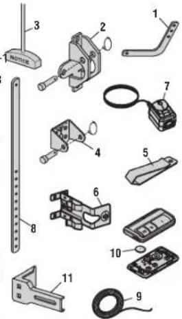
text_image
Exploded view diagram of mechanical components with numbered parts for identificationRepair Parts
Garage Door Opener Parts Model 87504-267
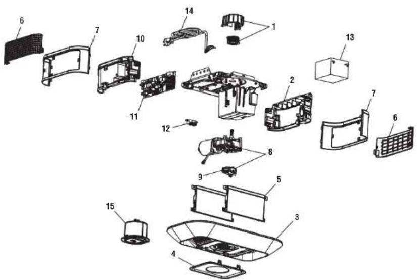
text_image
Exploded view diagram of a smart home appliance with numbered parts for identification| Description Part Number | |
| 1 Sprocket and Sprocket Cover with Screws 041C0589-2 | |
| 2 End panel 041-0185-000 | |
| 3 Integrated LED Light Module 041-0186-000 | |
| 4 Badge with camera 041-0195-000 | |
| 5 Main Enclosure Cover 041-0190-000 | |
| 6 Control door panel 041-0192-000 | |
| 7 End panel cover | 041-0193-000 |
| 8 Motor with travel module | 041-0236-000 |
| 9 Travel Module | 041D8071-4 |
| 10 Logic board end panel | 041-0183-00 |
| 11 Logic board | 050DCTBFMC |
| 12 Terminal block | 041A3150 |
| 13 Backup battery | 485LM |
| 14 Line cord | 041B4245-1 |
| 15 Camera | 041-0347-000 |
| Not Shown | |
| Wire harness | 041-0180-000 |
| Camera wire harness | 041-0349-000 |
| Transformer 041D0277-1 | |
Repair Parts
Rail Assembly Parts Models 87802
| Description Part Number | |
| 1 Chain - for 7 foot door 041D3484 | |
| Chain - for 8 foot door | 041D3483 |
| Chain - for 10 foot door | 041D3485 |
| Chain - for 12 foot door | 19-5812 |
| Chain - for 14 foot door | 19-5814 |
| 2 Chain Pulley Bracket 041A2780 | |
| 3 Master link 004A1008 | |
| 4 One - piece rail 7 feet 3707CH | |
| One - piece rail 8 feet | 3708CH |
| One - piece rail 10 feet | 3710CH |
| One - piece rail 12 feet | 3712RV |
| One - piece rail 14 feet | 3714RV |
| 5 Trolley Assembly Includes: Master Link (2), Clevis Pin (1), Ring (1), Belt Clip (1), Threaded Shaft (1), and Tensioner Assembly (1) | 041A3489 |
| 6 Chain Tensioner 041B4103-1 | |
| 7 Trolley Threaded Shaft | K109B0018 |
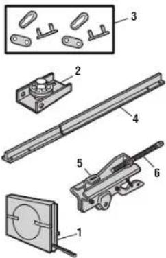
text_image
Technical diagram showing exploded view of mechanical components with numbered parts for identificationInstallation Parts
| Description | Part Number | |
| 1 | Curved door arm | 041B0035B |
| 2 | Door bracket with clevis pin and fastener | 041A504 |
| 3 | Emergency release rope and handle | 041A282 |
| 4 | Header bracket with clevis pin and fastener | 041A4353-1 |
| 5 | Remote control visor clip | K029B013 |
| 6 | Safety sensor bracket | 041-0155-000 |
| 7 | Safety sensor kit with receiving and sending sensors with 3 feet (.9 m) 2-conductor wire | 041-0136 |
| 8 | Straight door arm | 4178B0034B |
| 9 | White and red/white wire | 041B4494- |
| 10 | 3V CR2032 lithium battery | K010A0020 |
| 11 | Extension bracket (optional) | 041A5281-1 |
| Not Shown | ||
| Owner's manual | 114-5518-000 | |
| Multi-function Control Panel | 880LMW | |
| Remote Control | B93LM | |
| Installation hardware bag | 041A2770-17 | |

text_image
Exploded view diagram of mechanical components with numbered parts for identificationRepair Parts
Garage Door Opener Parts Model
87802
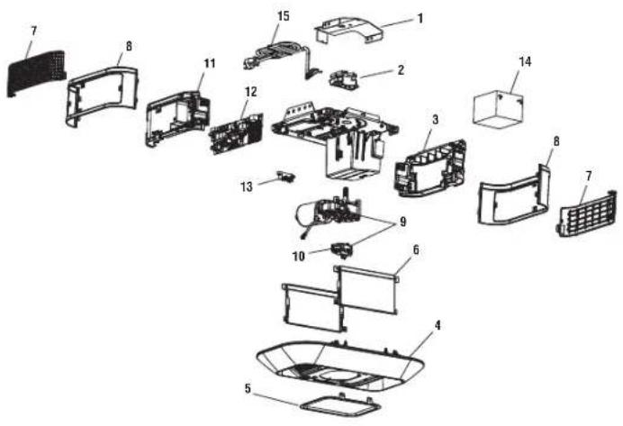
text_image
Exploded view diagram of a multi-case electronic device with numbered components for identification.Description Part Number
| 1 Chassis Support Bracket 041C5069 | |
| 2 Chain Spreader & Sprocket 041-0035 | |
| 3 End Panel, Battery Acces 041-0185-000 | |
| 4 Light Pod Kit, No Camera 041-0187-000 | |
| 5 Badge 041-0196-000 | |
| 6 Main Enclosure Cover 041-0190-000 | |
| 7 Control Door Panel | 041-0192-000 |
| 8 End panel cover | 041-0193-000 |
| 9 Motor with travel module | 041-0236-000 |
| 10 Travel Module | 041D8071-4 |
| 11 Logic board end panel | 041-0182-000 |
| 12 Logic board | 050DCTBLKFMC |
| 13 Terminal Block | 041A3150 |
| 14 Backup battery | 485LM |
| 15 Line cord | 041B4245-1 |
| Not Shown | |
| Wire harness | 041-0180-000 |
| Transformer 041D0277-1 | |
Repair Parts
Rail Assembly Parts 84602
| Description Part Number | |
| 1 Chain - for 7 foot door 041D3484Chain - for 8 foot doorChain - for 10 foot door | 041D3483041D3485 |
| 2 Chain Pulley Bracket 041A4813 | |
| 3 Master link 004A1008 | |
| 4 One-Piece Rail 7 feet (2.1 m) 1707LMOne-Piece Rail 8 feet (2.4 m)One-Piece Rail 10 feet (3 m) | 1708LM1710LM |
| 5 Trolley Assembly Includes: Master Link(2), Clevis Pin (1), Ring (1), Belt Clip (1),Threaded Shaft (1), andTensioner Assembly (1) | 041A3489 |
| 6 Tensioner Assembly 041B4103 | |
| 7 Trolley Threaded Shaft | 041A6689 |

text_image
Technical diagram showing exploded view of mechanical components with numbered parts for identificationInstallation Parts
| Description | Part Number | |
| 1 | Curved door arm | 041B0035B |
| 2 | Door bracket with clevis pin and fastener | 041A504 |
| 3 | Emergency release rope and handle | 041A282 |
| 4 | Header bracket with clevis pin and fastener | 041A4353-1 |
| 5 | Remote control visor clip | K029B013 |
| 6 | Safety sensor bracket | 041-0155-000 |
| 7 | Safety sensor kit with receiving and sending sensors with 3 feet (.9 m) 2-conductor wire | 041-0136 |
| 8 | Straight door arm | 4178B0034B |
| 9 | White and red/white wire | 041B4494- |
| 10 | 3V CR2032 lithium battery | K010A002 |
| 11 | Extension bracket (optional) | 041A5281-1 |
| Not Shown | ||
| Owner's manual | 114-5518-000 | |
| Multi-function Control Panel | 886LMW | |
| Remote Control | 893LM | |
| Installation hardware bag | 041A2770-17 | |

text_image
Exploded view diagram of mechanical components with numbered parts for identificationRepair Parts
Garage Door Opener Parts Model
84602
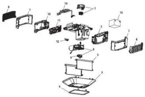
text_image
Exploded view diagram of a refrigerator with numbered parts for identificationDescription Part Number
| 1 Sprocket and Sprocket Cover with Screws 041B5348-2 | |
| 2 Non-logic board end panel 041-0185-000 | |
| 3 Integrated LED Light Module 041-0189-000 | |
| 4 Badge 041-0196-000 | |
| 5 Main Enclosure Cover 041-0191-000 | |
| 6 Control door panel 041-0192-000 | |
| 7 End panel cover | 041-0194-000 |
| 8 Motor with travel module | 041-0236-000 |
| 9 Travel Module | 041D8071-4 |
| 10 Logic board end panel | 041-0183-000 |
| 11 Logic board | 050DCTBFMC |
| 12 Terminal block | 041A3150 |
| 13 Backup battery | 485LM |
| 14 Line cord | 041B4245-1 |
| Not Shown | |
| Wire harness | 041-0180-000 |
| Transformer | 041A7635 |
Repair Parts
Rail Assembly Parts Model 84504R
| Description Part Number | |
| 1 Belt - for 7 foot door 041A5434-11ABelt - for 8 foot door | 041A5434-13A |
| Belt - for 10 foot door | 041A5434-14A |
| 2 Belt Pulley Bracket 041B5424 | |
| 3 Master link 004A1008 | |
| 4 One-Piece Rail 7 feet (2.1 m) 2777BDOne-Piece Rail 8 feet (2.4 m) | 2778BD |
| One-Piece Rail 10 feet (3 m) | 2770BD |
| 5 Trolley Assembly Includes: Master Link(2), Clevis Pin (1), Ring (1), Belt Clip (1),Threaded Shaft (1), andTensioner Assembly (1) | 041B3869-3A |
| 6 Tensioner Assembly 041B4103 | |
| 7 Trolley Threaded Shaft | 041A6689 |
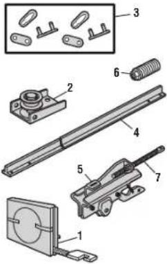
text_image
Technical diagram of a mechanical assembly with numbered components for identificationInstallation Parts
| Description | Part Number | |
| 1 | Curved door arm | 041B0035E |
| 2 | Door bracket with clevis pin and fastener | 041A504 |
| 3 | Emergency release rope and handle | 041A282 |
| 4 | Header bracket with clevis pin and fastener | 041A4353-1 |
| 5 | Remote control visor clip | K029B013 |
| 6 | Safety sensor bracket 041-0155-000 | |
| 7 | Safety sensor kit with receiving and sending sensors with 3 feet (.9 m) 2-conductor wire | 041-0136 |
| 8 | Straight door arm | 4178B0034B |
| 9 | White and red/white wire | 041B4494- |
| 10 | 3V CR2032 lithium battery | K010A002 |
| 11 | Extension bracket (optional) | 041A5281-1 |
| Not Shown | ||
| Installation hardware bag | 041A2770-17 | |
| Multi-function Control Panel | 882LMW | |
| Owner's manual | 114-5518-000 | |
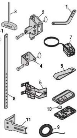
text_image
Exploded view diagram of mechanical components with numbered parts for identificationRepair Parts
Garage Door Opener Parts 84504R
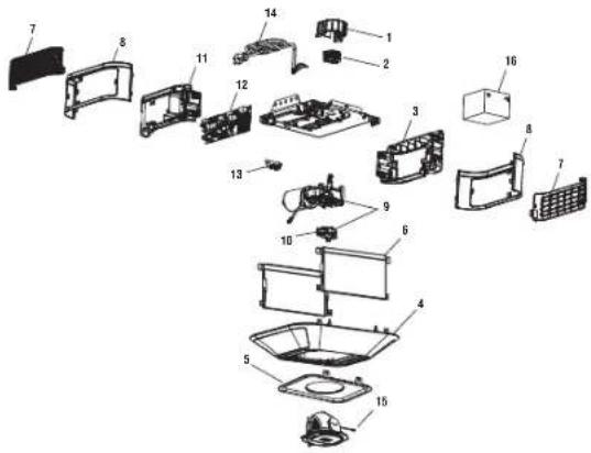
text_image
Exploded view diagram of a device with numbered parts for identification| Description Part Number | |
| 1 Sprocket cover 041A4371 | |
| 2 Gear and sprocket 041C0589-2 | |
| 3 Non-Logic Board End Panel 041-0185-000 | |
| 4 Dual Light Pod Kit 041-0188-000 | |
| 5 Badge 041-0196-000 | |
| 6 Main Enclosure cover 041-0191-000 | |
| 7 Control door panel | 041-0192-000 |
| 8 End panel cover | 041-0194-000 |
| 9 Motor with travel module | 041-0236-000 |
| 10 Travel module | 041D8071-4 |
| 11 Logic Board End Panel Cover | 041-0183-00 |
| 12 Logic board | 050DCTBFMC |
| 13 Terminal Block | 041A3150 |
| 14 Line Cord | 041B4245-1 |
| 15 Camera | 041-0347-000 |
| 16 Backup battery 485LM | |
| Not Shown | |
| Wire harness | 041-0180-000 |
| Camera wire harness | 041-0349-000 |
| Transformer, Wi-Fi Non-Battery Backup | 041D0277-2 |
Repair Parts
Rail Assembly Parts Model 84505R
| Description Part Number | |
| 1 Belt - for 7 foot door 041A5434-11ABelt - for 8 foot door | 041A5434-13A |
| Belt - for 10 foot door | 041A5434-14A |
| 2 Belt Pulley Bracket 041B5424 | |
| 3 Master link 004A1008 | |
| 4 One-Piece Rail 7 feet (2.1 m) 2777BDOne-Piece Rail 8 feet (2.4 m) | 2778BD |
| One-Piece Rail 10 feet (3 m) | 2770BD |
| 5 Trolley Assembly Includes: Master Link(2), Clevis Pin (1), Ring (1), Belt Clip (1),Threaded Shaft (1), andTensioner Assembly (1) | 041B3869-3A |
| 6 Tensioner Assembly 041B4103 | |
| 7 Trolley Threaded Shaft | 041A6689 |

text_image
Technical diagram of a mechanical assembly with numbered components for identificationInstallation Parts
| Description | Part Number | |
| 1 | Curved door arm | 041B0035E |
| 2 | Door bracket with clevis pin and fastener | 041A504 |
| 3 | Emergency release rope and handle | 041A282 |
| 4 | Header bracket with clevis pin and fastener | 041A4353-1 |
| 5 | Remote control visor clip | K029B013 |
| 6 | Safety sensor bracket 041-0155-000 | |
| 7 | Safety sensor kit with receiving and sending sensors with 3 feet (.9 m) 2-conductor wire | 041-0136 |
| 8 | Straight door arm | 4178B0034B |
| 9 | White and red/white wire | 041B4494- |
| 10 | 3V CR2032 lithium battery | K010A002 |
| 11 | Extension bracket (optional) | 041A5281-1 |
| Not Shown | ||
| Installation hardware bag | 041A2770-17 | |
| Multi-function Control Panel | 882LMW | |
| Owner's manual | 114-5518-000 | |

text_image
Exploded view diagram of mechanical components with numbered parts for identificationRepair Parts
Garage Door Opener Parts 84505R
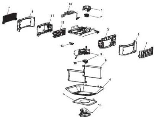
text_image
Exploded view diagram of a refrigerator with numbered parts for identification| Description Part Number | |
| 1 Sprocket cover 041A4371 | |
| 2 Gear and sprocket 041C0589-2 | |
| 3 End panel, No Battery Access 041-0184-000 | |
| 4 Dual Light Pod Kit 041-0188-000 | |
| 5 Badge 041-0196-000 | |
| 6 Main Enclosure cover 041-0191-000 | |
| 7 Control door panel | 041-0192-000 |
| 8 End panel cover | 041-0194-000 |
| 9 Motor with travel module | 041-0236-000 |
| 10 Travel module | 041D8071-4 |
| 11 Logic Board End Panel Cover | 041-0183-000 |
| 12 Logic board | 050DCTBFMC |
| 13 Terminal Block | 041A3150 |
| 14 Line Cord | 041B4245-1 |
| 15 Camera | 041-0347-000 |
| Not Shown | |
| Wire harness | 041-0180-000 |
| Camera wire harness | 041-0349-000 |
| Transformer, Wi-Fi Non-Battery Backup | 041D0277-2 |
CONTACT INFORMATION
Visit us online at:
LiftMaster.com
Before calling, please have the model number of the garage door opener. If you are calling about a troubleshooting issue, it is recommended that you have access to your garage door opener while calling. If you are ordering a repair part please have the following information: part number, part name, and model number.
Wi-Fi ^® is a registered trademark of Wi-Fi Alliance.
HomeLink ^® is a registered trademark of Gentex Corporation.
© 2022, LiftMaster
All Rights Reserved
natural_image
Exterior view of a modern lift master device (no visible text or symbols on body)Available on most iOS and Android Devices
LiftMaster®
Tabla de contenidos
Preparación
text_image
Diagram illustrating Wi-Fi connectivity with a smartphone displaying a Wi-Fi icon and a person holding a device near a staircase.text_image
A B C D E F G H K L M J S N O P Q R I emisor (1).Preparación
text_image
emisor (1). A B C F G D E K H L M S J N O P Q R Isuperior del
Preparación
text_image
A B C F G K D E emisor (1) H L M J N O P Q R IPreparación
text_image
A B C F G K D E emisor (1) L M J N O P I O QPreparación
text_image
A B C D E F G H K L M J N O P Q R I (2)Conjunto
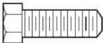
Perno hexagonal de 5/16'-18x7/8'

Tuerca
de 5/16'-18
FIGURA 1
instalaciones
natural_image
Technical line drawing of a cable support structure with no visible text or symbolsNo suministrado
7/8", arandelas de
del cabezal si el
sopore no FIGURA3
text_image
Technical diagram showing a device with a magnified view of its internal structure and a close-up of the component being inserted into a device.

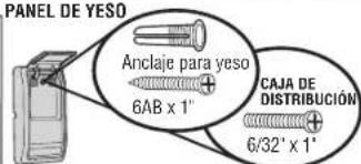
natural_image
Diagram showing a machine tool interacting with a device, with two circular insets illustrating the process (no text or symbols present)* Si es aplicable.
natural_image
Illustration of a house with a door and a hand holding a smartphone (no text or symbols)3
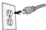
como se muestran.
3 Cargue la batería
text_image
"clic" "clic"Borrar la memoria
BORRETODOSLOS CONTROLES REMOTOS Y ENTRADAS SIN LLAVE
text_image
Safety warning sign with pictogram of a person using a scooter and no stop sign, indicating no accessibility or restriction.natural_image
Illustration of a person sitting with a crossed-out hand and a large 'no' symbol in the background (no text or symbols present)natural_image
Illustration of a hand using a spray gun to adjust or install a mechanical component (no text or symbols visible)natural_image
Exterior view of a modern garage with a white upward arrow indicating clearance (no text or symbols)natural_image
Interior view of a room with a person holding a tool near a window, no visible text or symbolsDoor & Access Systems Manufacturers Association International
Piezas de repuesto
text_image
Technical diagram of mechanical components with numbered parts, including parts like a sliding rod, spring, and bracket assembly.text_image
Exploded view diagram of a smart home appliance with numbered parts for identificationtext_image
Technical diagram showing exploded view of mechanical components with numbered parts for identificationtext_image
Exploded view diagram of a multi-case electronic device with numbered components for identification.text_image
Technical diagram showing exploded view of mechanical components with numbered parts for identificationtext_image
Exploded view diagram of a device with numbered parts for identificationtext_image
Exploded view diagram of a mechanical assembly with numbered parts for identificationtext_image
Exploded view diagram of a refrigerator internal components with numbered parts for identificationtext_image
Exploded view diagram of a mechanical assembly with numbered parts for identificationtext_image
Exploded view diagram of a refrigerator internal components with numbered parts for identificationnatural_image
Exterior view of a modern lift master device (no visible text or symbols on body)natural_image
Illustration of a smart home security system with a smartphone, Wi-Fi icon, and a person holding a tool (no text or symbols)B. Poulie et support
C. Support de porte
B. Poulie et support
C. Support de porte
text_image
(1), capteur A B C F G D E K H L M S J N O P Q R IPréparation
text_image
A B C F G D E capteur K H L M J N O P Q R IPréparation
text_image
A B C F G D E capteur K H L M J N O P Q R IPréparation
B. Poulie et support
C. Support de porte
text_image
A B C F G D E K H L M J capteur N O P Q R IAssemblage
text_image
MATERIAL Battery manufacturer has 10% pre-acquisition power inductors, fuel, and current parts to be acquired MATERIALS 87514 237-8490 Electrical power Power supply Electrical power Electrical power Electrical powertext_image
2 Bulons' attachments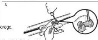
text_image
3 arage.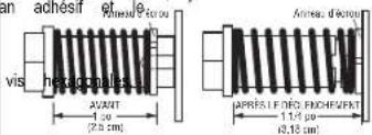
text_image
achesir vis hexagonales AVANT 1 cu (2.5 cm) APRES.I.F.DG.RICHWEERT 1.1/3 pu (3,18 cm)Assemblage
natural_image
Diagram showing a machine operation with zoomed-in views of the machine (no text or symbols present)* Le cas échéant.
natural_image
Illustration of a house with a door and a hand holding a car, no text or symbols present3

text_image
Safety warning sign with pictogram of a person using a scooter and no stop sign, indicating no accessibility restrictions.natural_image
Silhouette of a person reaching for a wall while another car is parked nearby (no text or symbols visible)natural_image
Illustration of a person sitting with arms crossed, enclosed in a prohibition symbol (no text or symbols present)natural_image
Illustration of a hand holding a spray bottle, with a tool inserted into a pipe (no text or symbols visible)Door & Access Systems Manufacturers Association International