41K4629 - Photoelectric sensor LIFT-MASTER - Free user manual and instructions
Find the device manual for free 41K4629 LIFT-MASTER in PDF.

| Product Type | Safety photoelectric sensor for garage door |
| Brand | LIFT-MASTER |
| Model | 41K4629 |
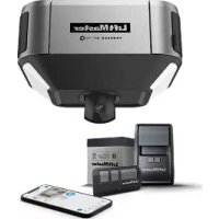
| Compatibility | LiftMaster FDC, FDCL, FDO, LGE, Logic 3, 4, 5.0 operators |
| Max Installation Height | 15 cm (6 in) above floor |
| Range | 2.1 to 9.1 m (7 to 30 ft) |
| Power Supply | From operator (wired) |
| Detection Type | Invisible infrared beam |
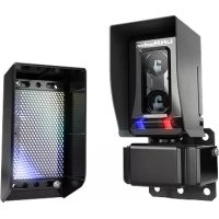
| LED Indicators | Green LED on emitter and receiver for alignment |
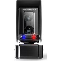
| Main Function | Obstacle detection for reversing door during closing |
| Installation | Wall or door track mounting, face to face |
| Housing Material | Durable plastic |
| Dimensions (approx.) | 5 x 3 x 3 cm (not specified, estimation) |
| Weight (approx.) | 50 g (not specified, estimation) |
| Operating Temperature | -20 °C to 60 °C (standard estimation) |
| Weather Protection | Designed for indoor/outdoor use with proper installation |
| Warranty | 1 year |
| Repairability | Parts not individually repairable; replace the entire unit |
| Cleaning | Wipe with a dry cloth; do not use solvents |
| Certifications | Compliant with UL, FCC standards (estimation) |
Frequently Asked Questions - 41K4629 LIFT-MASTER
User questions about 41K4629 LIFT-MASTER
0 question about this device. Answer the ones you know or ask your own.
Ask a new question about this device
Download the instructions for your Photoelectric sensor in PDF format for free! Find your manual 41K4629 - LIFT-MASTER and take your electronic device back in hand. On this page are published all the documents necessary for the use of your device. 41K4629 by LIFT-MASTER.
USER MANUAL 41K4629 LIFT-MASTER
NOTE: The images throughout this manual are for reference and your product may look different.
The CPS-U is a LiftMaster Monitored Entrapment Protection (LMEP) device and is compatible with LiftMaster Commercial Door Operators Models FDC, FDCL, FDO, LGE, Medium Duty Logic, Logic 3, Logic 4, and Logic 5.0.
IMPORTANT INFORMATION ABOUT THE PHOTOELECTRIC SENSOR
Be sure power to the operator is disconnected.
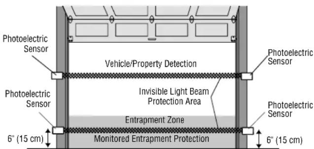
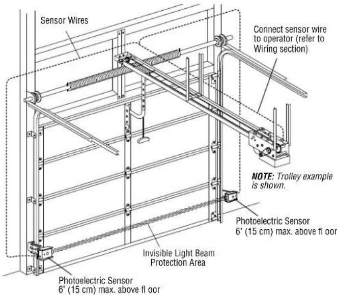
When properly connected and aligned, the photoelectric sensor will detect an obstruction in the path of its invisible light beam. If an obstruction breaks the light beam while the door is closing, the operator will stop and typically reverse to the full open position.
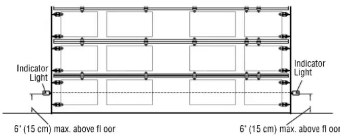
The sensors must be installed so that the emitter and receiver sensors face each other across the entrapment zone and the beam is no more than 6^ (15 cm) above the floor for a commercial door for entrapment protection. Either can be installed on the left or right of the entrapment zone as long as the sun never shines directly into the receiver eye lens.
The brackets must be securely fastened to a solid surface such as the wall framing. If installing in masonry construction, add a piece of wood at each location to avoid drilling extra holes in masonry if repositioning is necessary.
The invisible light beam path must be unobstructed. No part of the door (or door tracks, springs, hinges, rollers or other hardware) may interrupt the beam while the door is closing. If it does, use a piece of wood to build out each sensor mounting location to the minimum depth required for light beam clearance.
Additional photoelectric sensors may be added at heights greater than 6^ (15 cm) above the floor for vehicle/property detection.
WARNING
To prevent possible SERIOUS INJURY or DEATH from a closing door:
- Entrapment protection devices MUST be installed per the operator owner's manual for each entrapment zone.
- Be sure to DISCONNECT POWER to the operator BEFORE installing the photoelectric sensor.
- The door MUST be in the fully opened or closed position BEFORE installing the LiftMaster Monitored Entrapment Protection device.
- Correctly connect and align the photoelectric sensor.
- For entrapment protection, install the photoelectric sensor BEAM NO HIGHER than 6'' (15 cm) above the floor.

WARNING: This product can expose you to chemicals including lead, which are known to the State of California to cause cancer or birth defects or other reproductive harm. For more information go to www.P65Warnings.ca.gov
Facing the door from inside the building (installation procedures are the same for all door types).
Recommended installation for adjacent doors and more than one set of photoelectric sensors. For LOGIC 4 and LOGIC 5 Operators, a CPS3CARD is required to wire a second set of monitored photoelectric sensors.
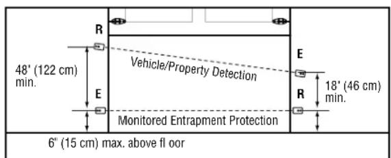
R = Receiver Sensor
E = Emitter Sensor
INSTALL
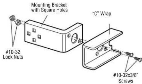
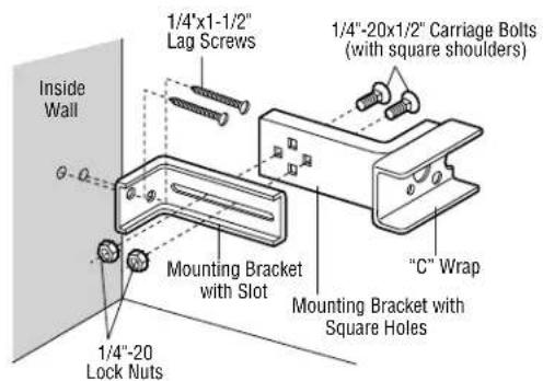
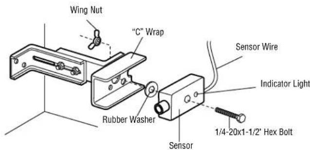
ASSEMBLE AND MOUNT THE BRACKETS
The following instructions show recommended assembly of the bracket(s) and "C" wrap based on the wall installation of the photoelectric sensors on each side of the door or on the door tracks themselves. There are also alternate mounting methods which may fit your installation requirements better. Make sure the wraps and brackets are aligned so the photoelectric sensors will face each other across the door. Mount sensors no more than 6'' (15 cm) above the floor and at a width between 7' - 30' (2.1 m - 9.1 m).
Fasten the "C" wraps to the mounting brackets having square holes, using hardware shown.
WALL INSTALLATION
- Connect each assembly to a slotted bracket, using the hardware shown. Note alignment of brackets for left and right sides of the door.
- Finger tighten the lock nuts.
- Use bracket mounting holes as a template to locate and drill (2) 3 / 16^ diameter pilot holes on both sides of the door, 4 - 6^* (10-15 cm) above the floor. Do not exceed 6^ (15 cm).
- Attach bracket assemblies with 1/4''x1 - 1/2'' lag screws.
- Adjust right and left side bracket assemblies to the same distance out from mounting surface. Make sure all door hardware obstructions are cleared. Tighten the nuts securely.
- Center each sensor in the bracket with the lenses pointing toward each other across the door.
- Attach the sensors to the brackets with the provided hardware. Finger tighten the receiving sensor wing nut. Securely tighten the sending sensor wing nut.
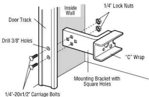
DOOR TRACK INSTALLATION
Discard slotted bracket. Drill 3 / 8'' holes in each track and fasten securely with hardware. Do not exceed 6'' (15 cm).
NOTE: Ensure the door track does not vibrate when the door is in motion. Excessive vibration can create nuisance reversals.
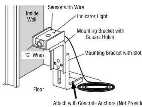
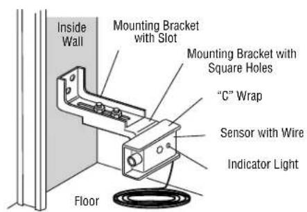
ALTERNATE WALL INSTALLATIONALTERNATE FLOOR INSTALLATION
INSTALL
MOUNT THE PHOTOELECTRIC SENSORS
- Center each sensor in the bracket with the lenses pointing toward each other across the door.
- Attach the sensors to the brackets with the provided hardware (as shown). Finger tighten the receiver sensor wing nut. Securely tighten the emitter sensor wing nut.
- Disconnect power to the operator.
- Run the sensor wires to the operator. Fasten the sensor wire appropriately.
- Connect the sensor wires to the operator (refer to WIRING section below).
WIRING
-
Connect power to the operator.
-
Align the photoelectric sensors so the green LED on the emitter sensor and the green LED on the receiver sensor glow steadily. If both green LEDs blink (and the invisible light beam path is not obstructed), alignment is required:
-
Loosen the receiver sensor wing nut to allow slight rotation of the sensor. Adjust sensor vertically and/or horizontally until both green indicator lights glow steadily.
-
When the indicator lights are glowing in both sensors, tighten the receiver sensor wing nut.
-
Press the OPEN button to fully open the door.
- Press the CLOSE button to close the door.
- Obstruct the light beam while the door is closing. The door should stop and reverse.
The operator will not close if the indicator lights are blinking, alerting you to the fact that the sensor is misaligned or obstructed.
TROUBLESHOOTING
If the emitter sensor and receiver sensor indicator lights do not glow steadily after installation, check for:
- Photoelectric sensor alignment
- Obstruction
Power to the operator - A short or broken wire
- Incorrect wiring between photoelectric sensors and the operator
If the receiver sensor indicator light is off or flashing (and the invisible light beam path is not obstructed), check alignment of the sensors and/or for an open wire to the receiver sensor.
If the emitter sensor and receiver sensor indicator lights are both glowing steadily but interrupting the photoelectric sensors does not cause the door to reverse when closing, check both sensors to make sure one sensor is the emitter and the other is a receiver sensor as indicated on the sensor housing.
NOTES:
- Direct sunlight to the receiver sensor may prevent the operator from closing even when both the emitter and receiver indicator lights are illuminated. Swapping the position of the emitter and receiver sensors will resolve this issue.
- Professional service is required if the operator closes the door when the photoelectric sensors are obstructed.
WARRANTY
LiftMaster warrants to the first consumer purchaser of this product that it is free from defect in materials and/or workmanship for a period of 1 year from the date of purchase.
FOR SERVICE OR TO ORDER REPAIR PARTS DIAL:
1-800-528-2806
LiftMaster.com