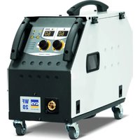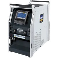
TIG 250 ACDC - Welding machine GYS - Free user manual and instructions
Find the device manual for free TIG 250 ACDC GYS in PDF.


User questions about TIG 250 ACDC GYS
0 question about this device. Answer the ones you know or ask your own.
Ask a new question about this device
Download the instructions for your Welding machine in PDF format for free! Find your manual TIG 250 ACDC - GYS and take your electronic device back in hand. On this page are published all the documents necessary for the use of your device. TIG 250 ACDC by GYS.
USER MANUAL TIG 250 ACDC GYS
natural_image
Line drawing of a desktop computer tower case with front panel, buttons, and ventilation grilles (no text or labels)FR 2 / 3-17 / 107-116
EN 2 / 18-31 / 107-116
DE 2 / 32-46 / 107-116
ES 2 / 57-61 / 107-116
RU 2 / 62-76 / 107-116
NL 2 / 77-91 / 107-116
IT 2 / 92-106 / 107-116
TIG 250 AC/DC
text_image
Technical diagram of a server rack with numbered components and labeled ports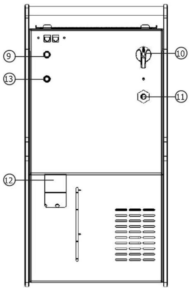
text_image
Technical diagram of a device front panel with numbered components and labeled parts
FIG-2
text_image
Technical diagram of a device with two circular components labeled 1 and 2, showing internal structure and directional arrows.AVERTISSEMENTS - RÈGLES DE SÉCURITÉ
CONSIGNE GENERALE

INSTALLATION – FONCTIONNEMENT PRODUIT
INTERFACE HOMME-MACHINE (IHM) (FIG-2)
text_image
MMA | PRO | OPTIONS | I 250 % 40 % 60 I = 250 A U = 30 VMMA EASY
text_image
MMA EASY I A 250 I = 250 A U = 30 V| Arc Force PA PF PE | |||
| Rutile 40% 20% 0% | |||
| Basique 60% 60% 20% | |||
| Cellulosique | 80% | - | 50% |
SOUDAGE A L'ÉLECTRODE TUNGSTÈNE SOUS GAZ INERTE (MODE TIG)
BRANCHEMENT ET CONSEILS
text_image
TIG DC g1.6 STD 2T DC I = 160 A \t = 3.0 sTIG DC STD
text_image
TIG DC p1.6 PLS 2T DC I = 160 A t = 3.0 sTIG DC PULSE
• TIG DC STANDARD
text_image
TIG | AC | 1.6 | STD | 2T | I = 160 A \t = 3.0 sTIG AC STD TIG AC PULSE
text_image
TIG | AC | φ1.6 | PLS | 2T I = 160 A \t = 3.0 s• TIG AC STANDARD
text_image
Simple diagram with a plus sign and a minus sign inside a rectangle, possibly indicating polarity or charge.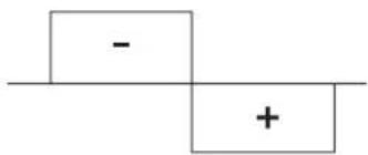
text_image
- + -
text_image
Simple diagram with a plus sign and a minus sign on a horizontal line, possibly indicating polarity or subtraction.natural_image
Close-up of a mechanical component with a pointed tip and angled edge, no visible text or symbolsnatural_image
Close-up of a mechanical component with a pointed tip inserted, no visible text or symbols• TIG AC PULSE
text_image
TIG DC μ1.6 SPOT 2T DC I = 100 A GraphTIG DC SPOT TIG AC SPOT
text_image
TIG AC μ1.6 SPOT 2T I=100 A Graphtext_image
TIG DC 81.6 TACK 2T DC I = 100 A Graphtext_image
Bouton principal T1 T2text_image
P L DB 1 5 2 P torch 4 L torch 3 DB torch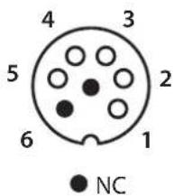
text_image
4 3 5 2 6 1 NC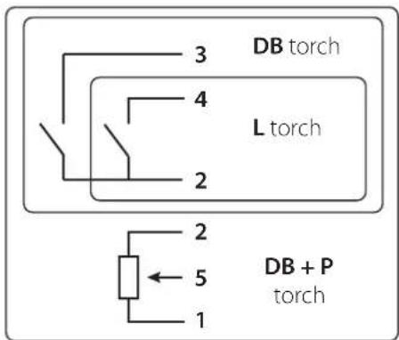
text_image
3 DB torch 4 L torch 2 2 5 1 DB + P torchtext_image
TIG ACMIX #1.6 STD 2T Remote Control Pedal R.C. Hand R.C. Automation - Connect 5 None OK I = 135 A \=0.3 sMESSAGES D'ERREUR, ANOMALIES, CAUSES, REMÈDES
Read and understand the following safety recommendations before using or servicing the unit.
Any change or servicing that is not specified in the instruction manual must not be undertaken.
The manufacturer is not liable for any injury or damage caused due to non-compliance with the instructions featured in this manual.
In the event of problems or uncertainties, please consult a qualified person to handle the installation properly.
ENVIRONMENT
This equipment must only be used for welding operations in accordance with the limits indicated on the descriptive panel and/or in the user manual. Safety instructions must be followed. In case of improper or unsafe use, the manufacturer cannot be held liable.
This equipment must be used and stored in a room free from dust, acid, flammable gas or any other corrosive agent. The same rules apply for storage. Operate the machine in an open, or well-ventilated area.
Operating temperature:
Use between -10 and +40°C (+14 and +104°F).
Storage between -20 and +55°C (-4 and 131°F).
Air humidity:
Lower or equal to 50% at 40°C (104°F).
Lower or equal to 90% at 20°C (68°F).
Altitude: Up to 1000 meters above sea level (3280 feet).
INDIVIDUAL PROTECTION & OTHERS
Arc welding can be dangerous and can cause serious injury or even death.
Welding exposes the user to dangerous heat, arc rays, electromagnetic fields, risk of electric shock, noise and gas fumes. People wearing pacemakers are advised to consult a doctor before using the welding machine.
To protect oneself as well as others, ensure the following safety precautions are taken:

In order to protect you from burns and radiations, wear clothing without turn-up or cuffs. These clothes must be insulating, dry, fireproof, in good condition and cover the whole body.

Wear protective gloves which guarantee electrical and thermal insulation.

Use sufficient welding protective gear for the whole body: hood, gloves, jacket, trousers... (varies depending on the application/operation). Protect the eyes during cleaning operations. Contact lenses are prohibited during use.
It may be necessary to install fireproof welding curtains to protect the area against arc rays, weld spatter and sparks.
Inform the people around the working area to never look at the arc nor the molten metal, and to wear protective clothes.

Ensure ear protection is worn by the operator if the work exceeds the authorised noise limit (the same applies to any person in the welding area).
Keep hands, hair and clothes away from moving parts such as fans, and engines.
Never remove the safety covers from the cooling unit when the machine is plugged in. The manufacturer is not liable for any injury or damage caused due to non-compliance with the safety precautions.

Parts that have just been welded will be hot and may cause burns when touched. When servicing the torch or electrode holder, make sure that it is cold enough by waiting at least 10 minutes before doing so. When using a water-cooled torch, make sure that the cooling unit is switched on to avoid any burns that could potentially be caused by the liquid.
It is important to secure the working area before leaving it to ensure protection of the goods and the safety of people.
WELDING FUMES AND GAS

The fumes, gases and dust issued by the welding are dangerous for the health. It is mandatory to ensure adequate ventilation and/or extraction to keep fumes and gases away from the work area. A fresh air mask is recommended in cases in case of insufficient ventilation in the workplace.
Check that the aspiration it is efficient by controlling compared safety standards.
Care must be taken when welding in small areas, and the operator will need supervision from a safe distance. Welding certain pieces of metal containing lead, cadmium, zinc, mercury or beryllium can be extremely toxic. The user will also need to degrease the workpiece before welding.
Gas cylinders must be stored in an open or ventilated area. The cylinders must be in a vertical position secured to a support or trolley.
Do not weld in areas where grease or paint are stored.
FIRE AND EXPLOSIONS RISKS
Protect the entire welding area. Compressed gas containers and other inflammable material must be moved to a minimum safe distance of 11 meters.
A fire extinguisher must be readily available near the welding operations.
Be careful of spatter and sparks, even through cracks.
It can be the source of a fire or an explosion.
Keep people, flammable objects and containers under pressure at a safe distance.
Welding of sealed containers or closed pipes should be prohibited, and if opened, the operator must remove any inflammable or explosive materials (oil, petrol, gas...).
Grinding operations should not be directed towards the device itself, the power supply or any flammable materials.
GAS BOTTLE

Gas leaking from the cylinder can lead to suffocation if present in high concentrations around the work area.
Transport must be done safely: Cylinders closed and product off. Always keep cylinders in an upright position securely chained to a fixed support or trolley.
Close the bottle after any welding operation. Be wary of temperature changes or exposure to sunlight.
Cylinders should be located away from areas where they may be struck or subjected to physical damage.
Always keep gas bottles at a safe distance from arc welding or cutting operations, and any source of heat, sparks or flames.
Be careful when opening the valve on the gas bottle, it is necessary to remove the tip of the valve and make sure the gas meets your welding requirements.
ELECTRICAL SAFETY

The machine must be connected to an earthed electrical supply. Use the recommended fuse size.
An electrical discharge can directly or indirectly cause serious or deadly accidents.
Do not touch any live part of the machine (inside or outside) when it is plugged in (Torches, earth cable, cables, electrodes) because they are connected to the welding circuit.
Before opening the device, it is imperative to disconnect it from the mains and wait 2 minutes, so that all the capacitors are discharged.
Do not touch the torch or electrode holder and earth clamp at the same time.
Damaged cables and torches must be changed by a qualified and skilled professional.
Always use the correct size of DIN connectors.
Always wear dry clothes in good condition, in order to be insulated from the electrical circuit. Wear insulating shoes, regardless of the environment in which you work in.
EMC CLASSIFICATION

These Class A devices are not intended to be used on a residential site where the electric current is supplied by the public network, with a low voltage power supply. There may be potential difficulties in ensuring electromagnetic compatibility on these sites, because of the interferences, as well as radio frequencies.

This equipment does not comply with IEC 61000-3-12 and is intended for connection to private low voltage networks connected to the public supply network only at medium and high voltage level. If connected to a public low voltage supply network, it is the responsibility of the installer or user of the equipment to ensure, by consulting the distribution network operator, that the equipment can be connected.
ELECTROMAGNETIC INTERFERENCES
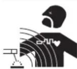
The electric currents flowing through a conductor cause electrical and magnetic fields (EMF). The welding current generates an EMF field around the welding circuit and the welding equipment.
The EMF fields may disrupt some medical implants, such as pacemakers. Protection measures should be taken for people wearing medical implants. For example, access restrictions for passers-by or an individual risk evaluation for the welders.
All welders should take the following precautions in order to minimise exposure to the electromagnetic fields (EMF) generated by the welding circuit::
- position the welding cables together – if possible, attach them;
- keep your head and torso as far as possible from the welding circuit;
- never enroll the cables around your body;
-
never position your body between the welding cables. Hold both welding cables on the same side of your body;
-
connect the earth clamp as close as possible to the area being welded;
- do not work too close to, do not lean and do not sit on the welding machine
- do not weld when you're carrying the welding machine or its wire feeder.

People wearing pacemakers are advised to consult their doctor before using this device. Exposure to electromagnetic fields while welding may have other health effects which are not yet known.
RECOMMENDATIONS TO ASSESS THE WELDING AREA AND WELDING INSTALLATION
Overview
The user is responsible for installing and using the arc welding equipment in accordance with the manufacturer's instructions. If electromagnetic disturbances are detected, it is the responsibility of the user of the arc welding equipment to resolve the situation with the manufacturer's technical assistance. In some cases, this remedial action may be as simple as earthing the welding circuit. In other cases, it may be necessary to construct an electromagnetic shield around the welding power source and around the entire piece by fitting input filters. In all cases, electromagnetic interferences must be reduced until they are no longer bothersome.
Welding area assessment
Before installing the machine, the user must evaluate the possible electromagnetic problems that may arise in the area where the installation is planned.
. In particular, it should consider the following:
a) the presence of other power cables (power supply cables, telephone cables, command cable, etc...) above, below and on the sides of the arc welding machine;
b) television transmitters and receivers;
c) computers and other hardware;
d) critical safety equipment such as industrial machine protections;
e) the health and safety of the people in the area such as people with pacemakers or hearing aids;
f) calibration and measuring equipment;
g) the isolation of the equipment from other machinery.
The user will have to make sure that the devices and equipments that are in the same room are compatible with each other. This may require extra precautions;
h) make sure of the exact hour when the welding and/or other operations will take place.
The surface of the area to be considered around the device depends on the building's structure and other activities that take place there. The area taken in consideration can be larger than the limits determined by the companies.
Welding area assessment
Besides the welding area, the assessment of the arc welding systems installation itself can be used to identify and resolve cases of disturbances. The assessment of emissions must include in situ measurements as specified in Article 10 of CISPR 11. In situ measurements can also be used to confirm the effectiveness of mitigation measures.
RECOMMENDATION ON METHODS OF ELECTROMAGNETIC EMISSIONS REDUCTION
a. National power grid: The arc welding machine must be connected to the national power grid in accordance with the manufacturer's recommendation. If interferences occur, it may be necessary to take additional preventive measures such as the filtering of the power supply network. Consideration should be given to shielding the power supply cable in a metal conduit. It is necessary to ensure the shielding's electrical continuity along the cable's entire length. The shielding should be connected to the welding machine to ensure good electrical contact between the metal conduct and the casing of the welding machine.
b. Maintenance of the arc welding equipment: The arc welding machine should be submitted to a routine maintenance check according to the manufacturer's recommendations. All accesses, service doors and covers should be closed and properly locked when the arc welding equipment is on.. The arc welding equipment must not be modified in any way, except for the changes and settings outlined in the manufacturer's instructions. The spark gap of the arc start and arc stabilization devices must be adjusted and maintained according to the manufacturer's recommendations.
c. Welding cables: Cables must be as short as possible, close to each other and close to the ground, if not on the ground.
d. Electrical bonding : consideration should be given to bonding all metal objects in the surrounding area. However, metal objects connected to the workpiece increase the riskof electric shock if the operator touches both these metal elements and the electrode. It is necessary to insulate the operator from such metal objects.
e. Earthing of the welded part: When the part is not earthed - due to electrical safety reasons or because of its size and its location (which is the case with ship hulls or metallic building structures), the earthing of the part can, in some cases but not systematically, reduce emissions It is preferable to avoid the earthing of parts that could increase the risk of injury to the users or damage other electrical equipment. If necessary, it is appropriate that the earthing of the part is done directly, but in some countries that do not allow such a direct connection, it is appropriate that the connection is made with a capacitor selected according to national regulations.
f. Protection and plating : The selective protection and plating of other cables and devices in the area can reduce perturbation issues. The protection of the entire welding area can be considered for specific situations.
TRANSPORT AND TRANSIT OF THE MACHINE

The welding power source is equipped with top handles for hand carrying. Be careful not to underestimate its weight. The handles are not considered as a means of slinging.
Do not use the cables or torch to move the welding current source. It must be moved in a vertical position.
Do not move the power source over people or objects.
Never lift a gas cylinder and the power source at the same time. Their transport standards are different.
INSTALLATION
Rules to follow:
- Put the machine on the floor (maximum incline of 10^ .)
- Ensure the work area has sufficient ventilation for welding, and that there is easy access to the control panel.
- The machine must not be used in an area with conductive metal dusts.
- The machine must be placed in a sheltered area away from rain or direct sunlight.
• The machine protection level is IP23, which means :
- Protection against access to dangerous parts from solid bodies of a ≥12.5mm diameter and,
- Protection against the rain inclined at 60% towards the vertical.
These devices can be used outside in accordance with the IP23 protection index.
The power cables, extensions and welding cables must be fully uncoiled to prevent overheating.

The manufacturer does not incur any responsibility regarding damages to both objects and persons that result from an incorrect and/or dangerous use of the machine.
MAINTENANCE / RECOMMENDATIONS


- Maintenance should only be carried out by a qualified person. Annual maintenance is recommended.
- Ensure the machine is unplugged from the mains, and wait for two minutes before carrying out maintenance work. DANGER High Voltage and Currents inside the machine.
- Remove the casing 2 or 3 times a year to remove any excess dust. Take this opportunity to have the electrical connections checked by a qualified person, with an insulated tool.
- Regularly check the condition of the power supply cable. If the power cable or connection cables are damaged, they must be replaced by the manufacturer, its after sales service or an equally qualified person to prevent danger.
- Ensure the ventilation holes of the device are not blocked to allow adequate air circulation.
- Do not use this equipment to thaw pipes, to charge batteries, or to start any engine.
- Do not use this welding current/voltage source for thawing pipes, recharging batteries/accumulators or starting motors.
The coolant should be changed every 12 months to avoid deposits that could disrupt the cooling system of the torch. Any leaks or residues of the product, after use, should be treated in an appropriate purification plant. If possible, the product should be recycled. Spent fluid must not be emptied into waterways, pits or drainage systems. Diluted fluid should not be emptied into the sewerage system, unless permitted by local regulations.
INSTALLATION – PRODUCT OPERATION
Only qualified personnel authorized by the manufacturer should perform the installation of the welding equipment. During set up, the operator must ensure that the machine is unplugged. Connecting generators in a series or a parallel circuit is forbidden.
HARDWARE DESCRIPTION (FIG-1)
The TIG 250 AC/DC is an Inverter welding unit to be used with refractory electrodes (TIG) in direct (DC) or alternative (AC) current.
TIG welding requires gas shield protection of pure gas (Argon).
The MMA process can wel all types of electrodes : rutile, basic, stainless and cast iron.
The TIG 250 AC/DC can be equipped with a remote control (ref. 045675), foot pedal (ref. 045682) or an automatic command (CONNECT-5).
1- Display + incremental buttons 8- Input for remote control
2- Positive Polarity socket 9- 5A fuse holder
3- Negative polarity socket 10- ON / OFF switch
4- Torch gas connection 11- Power cable
5- Trigger connector 12- Coolant tank inlet
6- Coolant inlet connector 13- Gas connection
7- Coolant outlet connector 14- Priming hose
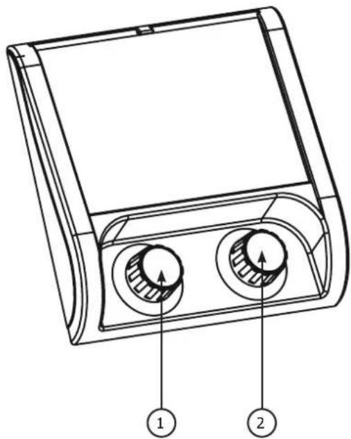
INTERFACE (MMI) (FIG-2)
The control board is made of a colour TFT screen and two potentiometers. It can be operated in 3 different modes:
- Mode 1 or Standby mode: with potentiometer 1 you will be able to set the welding current, and with potentiometer 2 the parameters related to the welding current.
- Mode 2 ou Welding mode : by pushing potentiometer 1 you will have access to the top menu. Then by turning the button, you may select the welding mode. You may exit this menu by waiting 8s or by pushing potentiometer 2 -> back to Mode 1.
- Mode 3 ou Settings mode : by pushing potentiometer 2 you will have access to the welding parameters and may select one of them by turning the potentiometer. You may exit this menu by waiting 8s or by pushing potentiometer 2 -> back to Mode 1.
POWER SUPPLY-START-UP
- This equipment is supplied with a 16A EN 60309-1 type plug and should only be used on a three-phase 400V (50-60 Hz) four-wire electrical installation with an earthed neutral.
The effective absorbed current (I1eff) is indicated on the equipment, for maximum use conditions. Check that the power supply and its protection (fuse and/or circuit breaker) are compatible with the current required for use. In some countries, it may be necessary to change the plug to allow use in maximum conditions.
- The power source is designed to operate on 400V +/- 15%. It goes into protection if the supply voltage is less than 330Vrms or greater than 490Vrms. (a fault code will appear on the display).
- Switching on is done by turning the on/off switch (I-10) to position I, conversely switching off is done by turning to position O. Caution! Never switch off the power supply when the welding current source is under load.
• Fan behaviour: In MMA mode, the fan runs continuously. In TIG mode, the fan runs only during the welding phase and then stops after cooling.
CONNECTION TO A GENERATOR
This equipment can operate with generators provided that the auxiliary power meets the following requirements:
- The voltage must be alternating, with an effective value of 400 V +/- 15%, and a peak voltage of less than 700 V,
- The frequency must be between 50 and 60 Hz.
It is imperative to check these conditions, as many generators produce high voltage spikes that can damage the equipment.
USE OF EXTENSION CORDS
All extension cords must be of a size and cross-section appropriate for the voltage of the equipment. Use an extension cord that complies with national regulations. Power, extension and welding cables should be fully unwound to avoid overheating.
| Input voltage | Length - Section of the extension cable (Length < 45m) |
| 400 V 4 mm ^2 |
PRIMING OF THE COOLING UNIT
When using the product for the first time or after the coolant tank has been completely emptied, the following procedure must be followed to prime the circulator with liquid:
- Fill the reservoir to its maximum level with coolant.
- Connect the coolant priming kit (I-14) to the unit's coolant connector (blue fitting). Place the other end of the kit in an empty container.
- Turn on the liquid circulator. To activate it, depending on the product, you will need to connect a torch and then pull the welding trigger, or simply power up the unit.
- The circulator should start instantly and the liquid should flow into the container. If the circulator still does not prime, turn off the power supply, inject compressed air into the Priming Kit to flush the liquid from the pipes and then restart the circulator.
- Once the pump has been primed (container filling with coolant), stop the chiller by pressing one of the buttons on the HMI.
- As soon as the liquid flows, the circulator is primed. Turn off the unit, disconnect the Priming Kit, top up the coolant in the reservoir and connect your system to the unit's fluid connections. Your cooling unit is primed and ready for operation.
LIQUID COOLING
The tank of the cooling unit must be filled to the recommended MAX level of the gauge on the front of the cooling unit, but never below the MIN level unless a warning message is displayed.
It is essential to use a specific coolant for welding machines with low electrical conductivity, being anti-corrosion and anti-freeze.
The use of other coolants, and in particular standard automotive coolant, can lead to the accumulation of solid deposits in the cooling circuit through electrolysis, thus degrading the cooling, and even clogging the circuit.
This recommended MAX level is essential to optimise the operating factors of the associated water-cooled torch.
Any damage to the machine caused by the use of a coolant other than the recommended type will not be considered under the warranty.
Ensure that the cooling unit (or generator with cooling unit) is disconnected from the power supply before connecting or disconnecting the torch liquid cooling hoses (inlet and outlet).
FUNCTION, MENU AND PICTOGRAM DESCRIPTIONS
| Function | Name on the display interface | Pictogram | TIG DC | TIG AC | MMA | Comment |
| Welding current Welding | current X X X |  | The required welding current depends on the thickness and the type of metal, as well as the work category / work piece. (A) | |||
| Welding voltage Voltage | X X X Welding voltage measure |  | ||||
| HotStart Overcurrent X | Adjustable overcurrent at the beginning of the welding (%) | |||||
| ArcForce | ArcForce |  | X | Overcurrent delivered to prevent sticking when the electrode enters the welding pool (%) | ||
| Polarity reversal |  | X | Easy reversal of the polarity in order to weld with different type of electrodes, without the need to disconnect the earth clamp and electrode holder | |||
| Position of the negative polarity |   | X | NEGATIVE polarity (-) | |||
| Indicator of the place of the positive polarity |  | X POSITIVE polarity (+). | |||
| HF ignition HF X X Arc ignition without contact | |||||
| Lift ignition LIFT X X Arc ignition with contact | |||||
| Pre-gas Pre-gas X X Time to purge the torch and to prevent the area with gas before ignition | |||||
| Starting current Starting current X X Pre current (A) |  | ||||
| Initial time Starting current X X Pre current duration (S) | [W508] | ||||
| Up slope current Upslope X X Minimum current to welding current (upslope phase) duration (S) | |||||
| Cold current (4TLog) I cold X X |  | Background welding current or cold current activated with a double button torch or in 4T LOG (A) | |||
| Cold current | I cold X X Base current or cold current in PULSE mode (A) | ||||
| Pulse balance | [PAAAS] | X | X | Base current or cold current balance in PULSE mode (%) | |
| PULSE Frequency | [YH4Q] | X | X | PULSATION frequency of the PULSE mode (Hz) | |
| Down slope current | [MHV2] | X X | Welding current to minimum current (downslope phase) duration, I Stop (S) to avoid weld defects and craters. | ||
| Ending current | [XDH4] | X X | Pre current (A) | ||
| Ending time |  | X X | Pre current duration (S) | ||
| Post gas |  | X X | Duration for which gas is released after the arc has stopped. It protects the weld pool and the electrode against oxidisation when the metal is cooling (S). | ||
| AC balance | [A330] | X Wave balance control of penetration and cleaning (%) | |||
| AC frequency | [OT4Q] | X AC welding frequency (Hz) | |||
| AC time | [B230] | X AC welding duration in AC MIX (S) | |||
| DC time | [E402] | X DC welding duration in AC MIX (S) | |||
| Spot time | [1483] | X | X | Spot time (s) | |
| TACK time | [7ER1] | X | Spot pulse duration (s) | ||
| Electrode diameter | ∅ | X X | Recommended diameter of the tungsten electrode to optimise the arc ignition in SYNERGIC mode (mm) | ||
| Metal to weld | Fe, CrNi, Cu/CuZn, AlMg, AlSi, Al99 | X | X | Selection of the metal to weld: Steel, Nickel-Chromium, Cusi or brass, Aluminium-Magnesium, Aluminium-Silicon in SYNERGIC mode | |
| Lap welding | [X070] | X X | SYNERGIC Mode. | ||
| Butt welding | [X222] | X X | SYNERGIC Mode. | ||
| Fillet welding |  | X X | SYNERGIC Mode. | ||
| Vertical down weld |  | X X | SYNERGIC Mode. | ||
| Thickness of the workpiece | [WOK7] | X X | Thickness adjustment of the workpiece in SYNERGIC mode | ||
| MMA process MMA | X | ||||
| TIG AC process | AC | X | |||
| TACK mode | TACK | X | |||
| TIG AC MIX mode | AC MIX | X | |||
| TIG DC process DC X | ||||||
| SYNERGIC process SYN | X X | |||||
| Standard mode STD X X | ||||||
| Pulse mode PULSE X X | ||||||
| Spot mode SPOT X X | ||||||
| 2T 2T X X 2T (time) torch mode | ||||||
| 4T 4T X X 4T (time) torch mode | ||||||
| 4T LOG 4T LOG X X 4T (time) LOG torch mode | ||||||
| Languages X X X | Language selection | [CK7] | ||||
| Interface lock |  | X | X | X | Locking the interface to prevent access to menus and parameters | |
| Interface unlock | [TXY] | XX | X | Unlocking the interface to allow access to menus and parameters (default code: 0000) | ||
| Password modification | [OW8Y] | X | X | X | Allow the modification of the password | |
| Parameters reset | RESET | X | X | X | Allow to restore to factory settings | |
| Identification | ID | X | X | X | After Sales module to identify the machine | |
| Backup menu |  | X | X | X | Menu to access to welding parameters features. | |
| Save | [XX3W] | X | X | X | Save the welding settings under the existing name. | |
| Save as | [OSW3] | X | X | X | Save the welding parameters under a new name. | |
| Open |  | X | X | X | Open an existing saved setting | |
| Delete |  | X | X | X | Delete an existing saved setting | |
| Welding current when a remote control is connected | Current |  | X | X | X | Current value adjustment when a remote control is present. |
| Cooling unit |  | XX | X | Cooling unit | ||
| Presence of a torch with potentiometer |  | XX | Presence of a torch with potentiometer | |||
| Presence of a remote control | [284V] | XX | X | Pictogram signalling that a remote control presence | ||
| Thermal protection | ↓ | X | X | X | Pictogram signalling thermal protection mode | |
ELECTRODE WELDING (MMA PROCESS)
CONNECTIONS AND RECOMMENDATIONS
- Connect the cables, electrode holder and earth clamp in the connectors,
- Respect the welding polarities and intensities indicated on the electrodes boxes,
- Remove the electrode from the electrode holder when the machine is not in use.
MMA WELDING PROCESSES
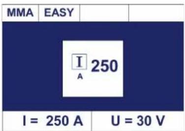
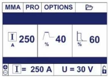
MMA PRO
text_image
MMA | PRO | OPTIONS | I 250 % 40 % 60 + I = 250 A U = 30 VMMA EASY
text_image
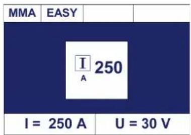
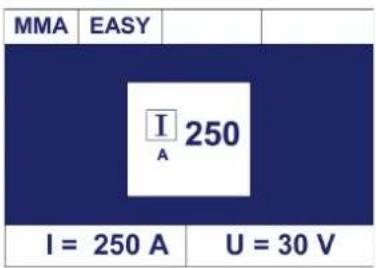
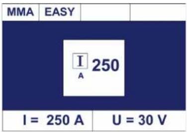
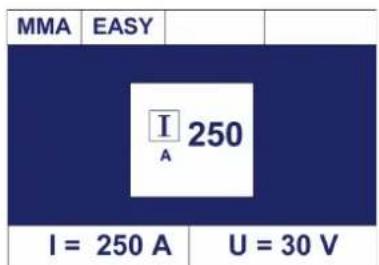
MMA EASY I A 250 I = 250 A U = 30 VPRO mode gives access to all product functions and settings.
EASY mode allows for a simplified interface with a single current setting.
PRO and EASY mode options:
| % HotStart % ArcForce Reverse polarity | |||
| EASY mode (40%) (40%) | |||
| PRO mode 0 - 100% 0 - 100% X | |||
RECOMMENDATIONS
- ArcForce
Depending on the electrode type and the welding position, we recommend the following settings:
| Arc Force PA PF PE | |||
| Rutile 40% 20% 0% | |||
| Basic 60% 60% 20% | |||
| Cellulosic | 80% | - | 50% |
TIG WELDING WITH INERT GAS (TIG PROCESS)
CONNECTIONS AND RECOMMENDATIONS
Connect the earth clamp to the positive connector (+).
Connect the torch to the negative plug (−), the trigger cable and the gas hose. Ensure that the torch is equipped and ready to weld, and that the consumables (Vise grip, ceramic gas nozzle, collet and collet body) are not damaged.
TIG WELDING PROCESSES
text_image
TIG DC μ1.6 STD 2T DC I = 160 A \t = 3.0 s TIG DC STD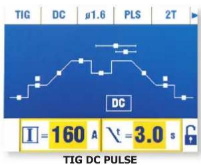
text_image
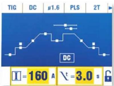
TIG DC g1.6 PLS 2T DC I=160 A \t=3.0 s TIG DC PULSE• TIG DC STANDARD
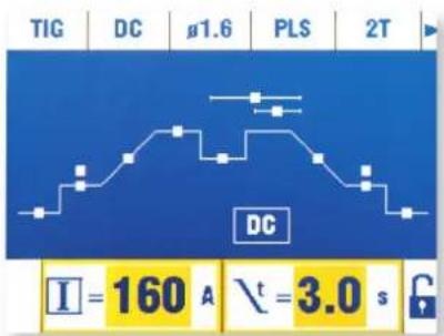
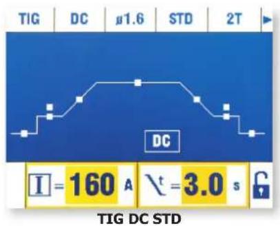
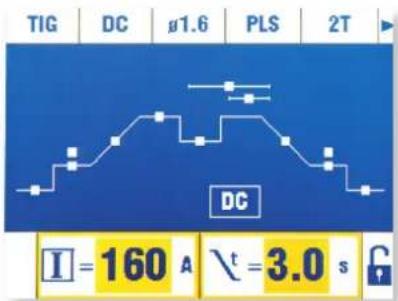
The TIG DC Standard process is recommended for high quality welding on most ferrous materials such as steel, stainless steel,, but also copper, copper alloys, titanium...
The many settings for current and gas allow to fine tune any weldong operation, from the ignition to the cooling of the weld bead.
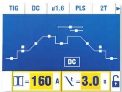
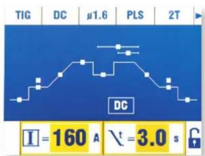
• TIG DC PULSE
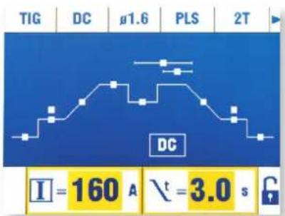
The TIG DC Pulse is recommended for thin metal sheets or for certain materials. This mode alternates between hot and cold current, which reduces the energy directed towards the workpiece
The settings are:
- The "I Cold" current is in percentage and sets up between 20% and 80% of the welding current.
The colder the current, the further it reduces the heat input during welding.
- The Pulse frequency (Hz Pulse) adjustable from 0.1 Hz to 2500Hz.
Thin sheets : Hz Pulse between 0.1 and 5Hz,
Downhand welding (PE): Hz Pulse between 5 and 20Hz,
Specific materials : Hz Pulse between 100 and 2500Hz,
The Pulse balance (%T_PULSE) is the % of cold current set up during a period (1: Period = 1/Hz Pulse)
Example:
The welding current "I" is set up at 100A.
I_Cold = 50%, which means = 50% of 100A = 50A.
Hz_Pulse is set up at 10Hz and %T_PULSE at 30%. The period of the signal will be at 1/10Hz = 100ms. The time of « I Cold » will be at 30% of this period, 30ms.
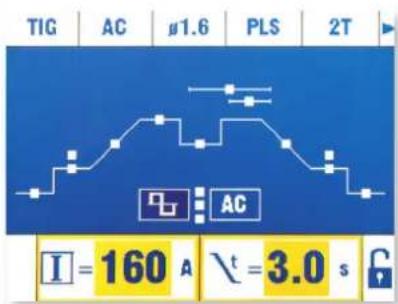
TIG AC WELDING PROCESSES
text_image
TIG | AC | 1.6 | STD | 2T | I = 160 A \t = 3.0 sTIG AC STD TIG AC PULSE
text_image
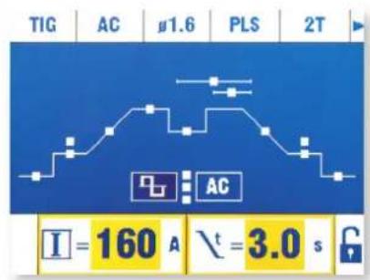
TIG | AC #1.6 | PLS | 2T I = 160 A \t = 3.0 s• TIG AC STANDARD
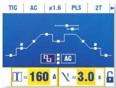
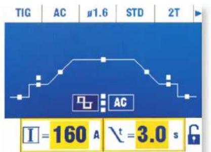
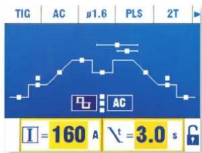
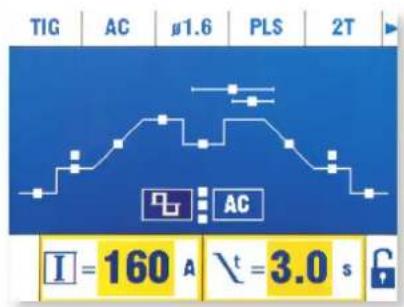
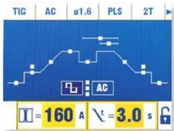
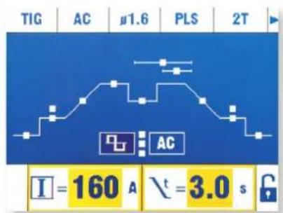
This TIG AC Standard mode is recommended to weld aluminium and alloys. (Al, AlSi, AlMg, AlMn...). AC current is essential to weld aluminium.
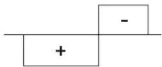
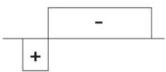
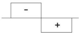
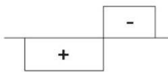
Balance (%T_AC): during the positive wave, oxidation is broken. During the negative wave, the electrode cools and the parts are welded (penetration). By modifying the ratio between 2 alternatives through the balance adjustment, you choose either cleaning or penetration (the default value is 30% ).
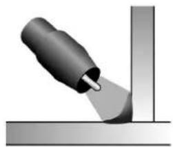
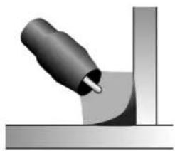
Frequency (Hz AC): the frequency enables adjustment of the arc concentration. The higher the frequency, the more concentrated the arc. The lower the frequency the wider the arc will be.
text_image
-
text_image
- + -
text_image
Simple diagram with a plus sign and a minus sign on a horizontal line, possibly indicating addition or subtraction.Balance : 20 % Maximum penetration 50 % 60 % Maximum cleaning (scraping)
natural_image
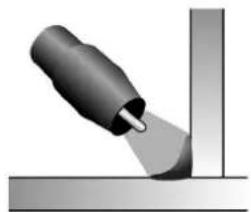
Illustration of a mechanical tool interacting with a surface (no text or symbols visible)High frequency Low frequency
natural_image
Close-up of a mechanical component with a metallic handle and curved surface (no text or symbols visible)• TIG AC PULSE
The TIG AC Pulse is recommended for thin metal sheets, see details in the TIG DC PULSE section.
TIG AC/DC SPECIAL WELDING PROCESSES
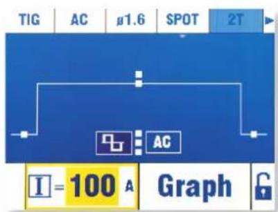
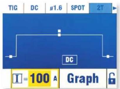
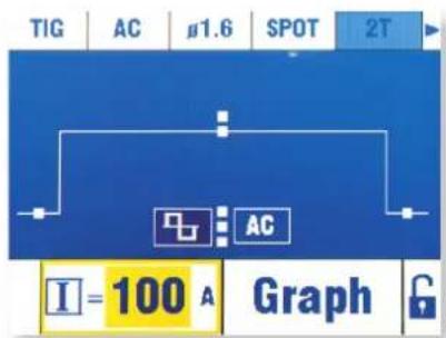
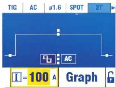
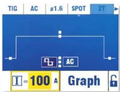
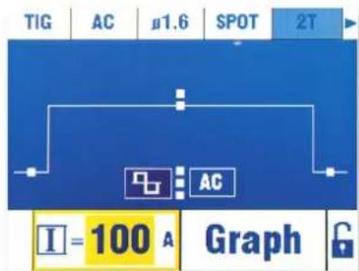
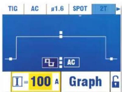
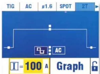
This mode is recommended to pre-assemble workpieces before welding.
The adjustable spot weld duration enables control of the weld time for better spot welding results and an non-oxidised spot.
text_image
TIG DC μ1.6 SPOT 2T DC I = 100 A GraphTIG DC SPOT TIG AC SPOT
text_image
TIG AC μ1.6 SPOT 2T I=100 A GraphSettings and options
| Pictogram | |
| Designation Spot time | |
| Value Manual, | 0.1s – 20s |
- Spotting - TACK (TIG DC)
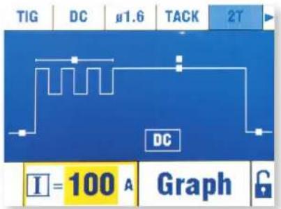
This mode can also pre-assemble workpieces, but in two phases: first phase is DC pulse which concentrates the arc for enhanced penetration, followed by a DC standard phase which enlarges the arc and the weld pool for a good spot.
The adjustable duration of each phase enables control of the weld time for better spot welding results and an non-oxidised spot.
text_image
TIG DC μ1.6 TACK 2T DC I = 100 A GraphSettings and options
| Pictogram | ||
| Designation | Spot pulse duration (s) | Spot time |
| Value 0.1s - 20s | Manual, 0.1s – | 20s |
TIG SYNERGIC
The SYNERGIC mode is a simplified mode which offers an advised configuration for the welding from 4 essential data.. The four settings are :
1- The type of metal of the workpiece: Iron and Steel (Fe), Nickel Chromium (NiCr), Copper and alloys (Cu/CuZn), Aluminium Magnesium, Aluminium Silicon and Aluminium 99% (Al99).
2- The type of joint: fillet, butt, lap and vertical down welding.
3- The diameter of the tungsten used in order to set the range of welding current without deteriorating it, and to optimise the ignition.
4- The thickness of the metal to weld
This mode can be of help to easily set weld parameters when you have just bought the machine. At any moment, the operator will be able to come back to the normal mode without losing the current parameters set up in STD mode. Every SYNERGIC setting will be saved and the user will be able to change them afterwards. This allows the operator to start welding with a number of parameters already set up.
SELECT IGNITION MODE
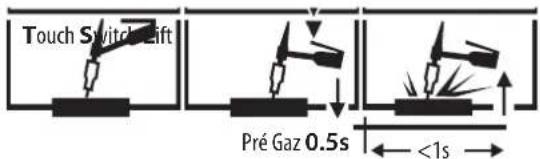
TIG HF: High Frequency start without contact
TIG LIFT : Contact start (for environments sensitive to HF disturbances).
text_image
Touch Switch Lift Pré Gaz 0.5s <1s1- Touch the workpiece with the electrode
2- Press the trigger on the torch
3- Pull back the torch to lift the electrode.
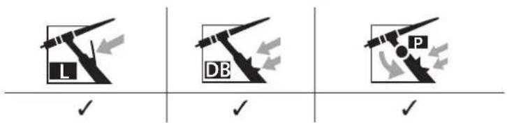
COMPATIBLE TORCHES
text_image
L DB PTORCHES AND TRIGGER MODES
For the 1 button torch, the button is called «main button».
For the 2 buttons torch, the first button is called «main button» and the second button is called «secondary button».
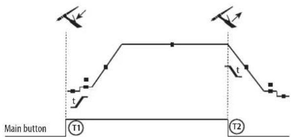
2T MODE
text_image
Main button T1 t t T2T1 - The main button is pressed, the welding cycle starts (PreGas, I_Start, UpSlope and welding).
T2 - The main button is released, the welding cycle is stopped (DownSlope, I_Stop, PostGas).
For the double button torch and in 2T mode only, the secondary button works like the main button.
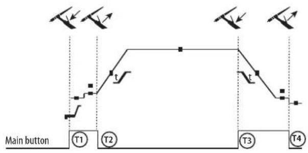
4T MODE
flowchart
graph TD
    A["Main button"] --> B["T1"]
    B --> C["T2"]
    C --> D["T3"]
    D --> E["T4"]
    style A fill:#f9f,stroke:#333
    style B fill:#ccf,stroke:#333
    style C fill:#cfc,stroke:#333
    style D fill:#fcc,stroke:#333
    style E fill:#cff,stroke:#333
T1 - The main button is pressed, the cycle starts at PreGas and stops in the I_Start phase.
T2 - The main button is released, the cycle continues in UpSlope and in welding.
T3 - The main button is pressed, the cycle switches to DownSlope and stops in I_Stop.
T4 - The main button is released, the cycle ends with PostGas.
Nb : for torches, double button and double button with potentiometer => command « up/welding current » and active potentiometer, command «low » inactive.
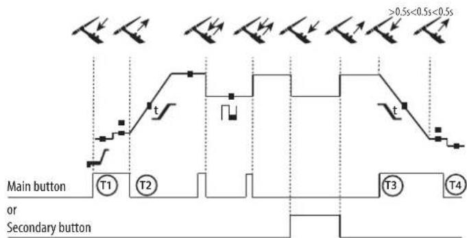
4T MODE log
text_image
≥0.5s<0.5s<0.5s t Main button T1 T2 or Secondary button t3 T4T1 - The main button is pressed, the cycle starts at PreGas and stops in the I_Start phase.
T2 - The main button is released, the cycle continues in UpSlope and in welding.
LOG : this mode is used during welding :
- A brief press of the main button (<0.5s), the current switches from I welding current to I cold and vice versa.
- the secondary button is kept pressed, the welding current switches from I welding current to I cold
- the secondary button is kept released, the welding current switched from I cold to I welding current.
T3 – A long press on the main button (>0.5s), the cycle switches to DownSlope and stops in the I_Stop phase.
T4 - The main button is released, the cycle finishes with PostGas.
For this mode it may be convenient to use the dual button torch option or dual button with potentiometer. The «up» command keeps the same function as the single button or trigger torch. The «down» button can, when pressed, switch to the cold current. The potentiometer of the torch, where available, can control of the welding current from 50% to 100% of the value displayed.
Summary of the fuctions available by welding process, by arcing mode and by type of trigger
(*) only on 4T LOG
(**) only on AC
RECOMMENDED COMBINATIONS
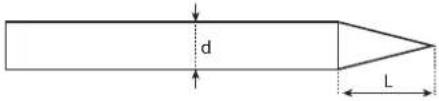
To optimise the welding process, it is recommended to grind the electrode prior to welding as described below: :
text_image
d LL = 3 x d for a low current.
L = 3 x d for a high current
The recommended electrodes are : E3, WL15.
In Tig AC mode :
The electrode does not need to be grinded, except for very low currents <50A. It is normal for a ball to appear at the end of the electrode. The ball size will become larger as the current and cleaning (scraping) is increased.
The recommended electrodes are : WP PUR, E3 and WL.
SAVE AND LOAD WELDING SETTINGS
The available save slots are : 100 in MMA, 100 in TIG DC and 50 in TIG AC.
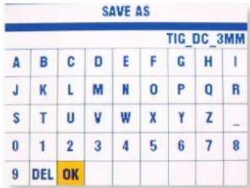
Save a welding setting under a chosen name.
In the file menu, the function « SAVE AS » is identified with the pictogram
text_image
SAVE AS TIG_DC_3MM A B C D E F G H I J K L M N O P Q R S T U V W X Y Z _ 0 1 2 3 4 5 6 7 8 9 DEL OKThe operator can enter the name of the setting by typing it on the keyboard.
Once back in the welding menu, the screen will display the name of the setting.
If the saved setting is amended, the name will appear in red.
If the saved setting is not accurate anymore and some modifications have been made: in the file menu, the function «SAVE», identified by icon
☑, overwrites the old configuration and saves the new one. If the the saved setting is amended, the name will appear in red.
Open a saved setting
In the file menu ☐ the function «OPEN» gives access to the current list of settings
Password:
The default password for unlocking is: 0000.
If the password has been lost, the super password enables to unlock the product: MORFRES
The standard password is reset to: 0000.
COMMAND TRIGGER CONNECTOR
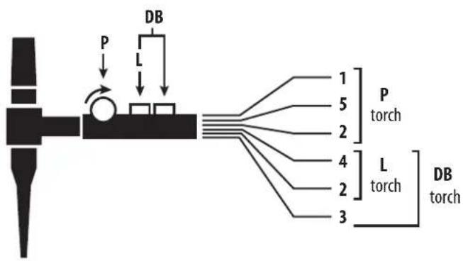
text_image
P L DB 1 5 2 P torch 4 L torch 3 DB torch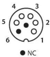
text_image
4 3 5 2 6 1 NC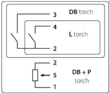
text_image
DB torch L torch 2 3 4 2 5 1 DB + P torchCabling diagram for the SRL18 torch. Electric diagram according to torch type.
| Torch type Wire description Pin | ||||
| Torch 2 triggers + potentiometer | Torch 2 triggers Torch 1 | trigger | Common/Earth 2 (green) | |
| Trigger 1 4 (white) | ||||
| Trigger 2 3 (brown) | ||||
| Common/Potentio-meter earth | 2 (grey) | |||
| VCC 1 (yellow) | ||||
| Cursor 5 (pink) | ||||
REMOTE CONTROL
The remote control operates in TIG mode and in MMA.
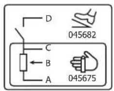
text_image
D 045682 C B A 045675ref. 045699 External view Electric diagram according to the remote control type.
Connections:
1- Plug the remote control into the connection at the back of the machine.
2- The machine will detect automatically the remote control and open a selection menu:
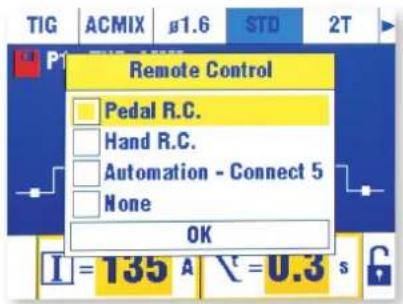
text_image
TIG ACMIX 1.6 STD 2T Remote Control Pedal R.C. Hand R.C. Automation - Connect 5 None OK I = 135 A \=0.3 s3- Select the remote control type
Connection
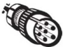
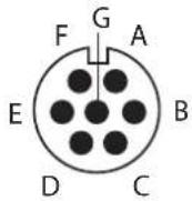
The machine is equipped with a female socket for remote control. The specific 7 pin male plug (optional ref.045699) enables connection to a manual remote control or foot pedal. For the cabling layout, please see the diagram below.
| REMOTE CONTROL TYPE Wire description Pin | ||||
| CONNECT-5 | Foot pedal Manual | remote control | VCC A | |
| Cursor B | ||||
| Common/Earth C | ||||
| Switch D | ||||
| AUTO-DETECT E | ||||
| ARC ON F | ||||
| REG I G | ||||
Operating :
• Manual remote control (option ref. 045675)
The remote control enables the variation of current from 50% to 100% of the set intensity In this configuration, all modes and functions of the machine are accessible and can be set.
• Foot pedal (option ref. 045682):
The pedal control enables variation of the current from the minimum current to 100% of the set intensity.
In TIG, the welding machine only operates in 2T mode. The upslope and downslope are not automatically managed by the current source, and are controlled by the user with the foot pedal.
- Connect 5 - automaton mode:
This mode enables to pilot the TIG 250 AC/DC from a console or from an automaton due to 5 pre-saved programs.
For the foot pedal, the «Switch (D)» enables to start or stop welding according to the chosen cycle. The voltage value for the «slider (B)» matches a program or the actual statut.
This voltage must be between 0 and 5V (step of 0.5V) which is linked to a program reminder:
- Actual status : 0 - 0.5V
- Program 1:0.5.-1V
- Program 2 : 1.0 - 1.5V
- Program 3 : 1.5 - 2V
- Program 4:2 - 2.5V
- Program 5 : 2.5 - 3.3V
An additional potentiometer enables to change the current (+/- 15%) either whilst welding or not. The information ARC ON (arc presence) enables the automaton to synchronise itself (Pull Up 100k entry, automaton side). Put the pin AUTO_DETECT to the earth enables to start the product without going through the selection window where you can select the type of remote control used.
The 5 loaded settings correspond to the first 5 saved programs (P1 to P5).
The signals' I/O (input/output) are protected at 6.1V.
Additional explanations are available on our website. (https://goo.gl/i146Ma).
Loading settings:

text_image
CONNECT 5 P1 TUB_2MM P2 TUB_3MM P3 TUB_4MM P4 TUB_5MM P5 TUB_6MM OK I = 135 A \ = 0.3 sTROUBLESHOOTING
This device integrates a default management system.
A series of messages displayed on the control board allows for a fault and anomalies diagnosis.
| ABNORMALITIES CAUSES SOLUTIONS | ||
| The machine does not deliver any current and the yellow pictogram signalling thermal protection is on. | The thermal protection has switched on. | Wait the end of the cooling cycle of about 5 min. The pictogram disappears. |
| The indicator is on but the product does not deliver any current. | The earth clamp or the electrode holder is not connected to the unit. | Check the connections |
| Voltage error The product is protected against overvoltage. | An power surge is at the origin of this message. | |
| Despite the filling the tank, the error message is still on. | The cooling liquid system is still not working and the fan is not on. | Check the fuse. |
| Unstable arc | Fault due to the tungsten electrode | Use an electrode size which is more suitable to the thickness of your metal / workpiece. |
| Use a tungsten electrode which is properly handled / prepared. | ||
| Gas flow too high Reduce the gas flow | ||
| The tungsten becomes oxidised and dull at the end of the welding | Welding area. Protect the welding area against draught. | |
| Post gas fault. | Increase the post gas duration | |
| Check and tighten every gas connection.Check the flowmeter with an no load ignition. | ||
| The tungsten electrode melts Polarity error Check that the earth is connected to the + | ||
| Water level fault | This default is due to an insufficient amount of cooling liquid in the system.The cooling unit is equipped with a water level sensor to ensure that the product operates normally | Fill up the tank to the indicated MAX level. |
| Despite the filling the tank, the error message is still on. | The cooling liquid system is still not working and the fan is not on. | Check the fuse. |
| Flow fault | This default is due to a obstructed torch (in its water circuit). The cooling unit is equipped with a water level sensor to ensure that the product operates normally | |
| Cooling unit fault | This occurs when the cooling unit is not detected anymore. | Switch off the product and check the electrical connection of the cooling unit. |
WARRANTY
The warranty covers faulty workmanship for 2 years from the date of purchase (parts and labour).
The warranty does not cover:
- Transit damage.
- Normal wear of parts (eg. : cables, clamps, etc..).
- Damages due to misuse (power supply error, dropping of equipment, disassembling).
- Environment related failures (pollution, rust, dust).
In case of failure, return the unit to your distributor together with:
- The proof of purchase (receipt etc ...)
- A description of the fault reported
text_image
MMA | PRO | OPTIONS | I 250 % 40 % 60 A I = 250 A U = 30 VMMA EASY
text_image
MMA EASY I A 250 I = 250 A U = 30 Vtext_image
TIG DC μ1.6 STD 2T DC I = 160 A \t = 3.0 sWIG DC STD
text_image
TIG DC μ1.6 PLS 2T DC I=160 A t=3.0 sWIG DC PULS
• WIG DC - Standard
text_image
TIG | AC | #1.6 | STD | 2T | I = 160 A \t = 3.0 sWIG AC STD WIG AC PULS
text_image
TIG | AC | 1.6 | PLS | 2T I = 160 A \t = 3.0 s• WIG AC - Standard
text_image
Simple diagram with a plus sign and a minus sign on a horizontal line, possibly indicating addition or subtraction.natural_image
Close-up of a mechanical component with a pointed tip and metallic surface (no text or symbols visible)natural_image
Close-up of a mechanical component with a curved tip and rectangular base (no text or symbols visible)• WIG AC PULS
text_image
TIG | DC | μ1.6 | SPOT | 2T DC I = 100 A Graph GWIG DC SPOT WIG AC SPOT
text_image
TIG AC μ1.6 SPOT 2T I = 100 A Graphtext_image
TIG DC a1.6 TACK 2T DC I = 100 A Graphtext_image
P L DB 1 5 2 4 2 3 P torch L torch DB torch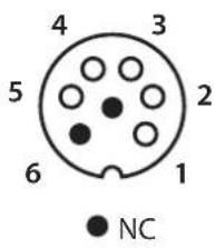
text_image
4 3 5 2 6 1 NC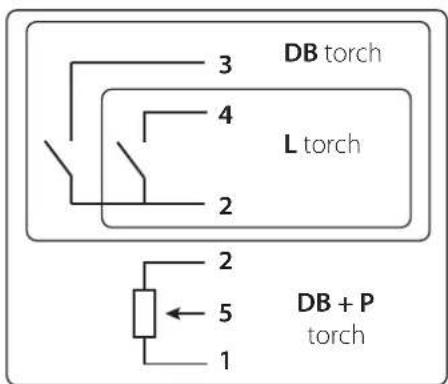
text_image
DB torch L torch 2 3 4 2 5 1 DB + P torchtext_image
TIG ACMIX #1.6 STD 2T Remote Control Pedal R.C. Hand R.C. Automation - Connect 5 None OK I = 135 A \=0.3 stext_image
MMA | PRO | OPTIONS | I 250 % 40 % 60 + I = 250 A U = 30 VMMA EASY
text_image
MMA EASY I A 250 I = 250 A U = 30 Vtext_image
TIG DC μ1.6 STD 2T DC I = 160 A \t = 3.0 sTIG DC STD
text_image
TIG DC μ1.6 PLS 2T DC I = 160 A t = 3.0 sTIG DC PULSE
• TIG DC STANDARD
text_image
TIG | AC | 1.6 | STD | 2T | I = 160 A \t = 3.0 sTIG AC STD TIG AC PULSE
text_image
TIG | AC | 1.6 | PLS | 2T I = 160 A \t = 3.0 s• TIG AC ESTÁNDAR
text_image
Simple diagram with a plus sign and a minus sign on a horizontal line, possibly indicating polarity or subtraction.natural_image
Close-up of a mechanical component with a pointed tip and angled edge, no visible text or symbolsnatural_image
Close-up of a mechanical component with a pointed tip inserted into a corner (no text or symbols visible)• TIG AC PULSE
text_image
TIG DC μ1.6 SPOT 2T DC I = 100 A GraphTIG DC SPOT TIG AC SPOT
text_image
TIG AC μ1.6 SPOT 2T I = 100 A Graphtext_image
TIG DC 81.6 TACK 2T DC I = 100 A Graphtext_image
P L DB 1 5 2 4 2 3 P torch L torch DB torch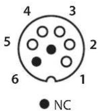
text_image
4 3 5 2 6 1 NC
text_image
DB torch L torch 2 3 4 2 5 1 DB + P torchtext_image
TIG ACMIX #1.6 STD 2T Remote Control Pedal R.C. Hand R.C. Automation - Connect 5 None OK I = 135 A \=0.3 stext_image
MMA | PRO | OPTIONS | I 250 % 40 % 60 A I = 250 A U = 30 V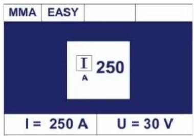
text_image
MMA EASY I A 250 I = 250 A U = 30 Vtext_image
TIG DC μ1.6 STD 2T DC I = 160 A \t = 3.0 sTIG DC STD
text_image
TIG DC μ1.6 PLS 2T DC I=160 A t=3.0 sTIG DC PULSE
• TIG DC STANDARD
text_image
TIG AC μ1.6 STD 2T I = 160 A \t = 3.0 sTIG AC STD TIG AC PULSE
text_image
TIG AC a1.6 PLS 2T I=160 A \t=3.0 s• TIG AC STANDARD
text_image
Simple diagram with a plus sign inside a rectangle and an minus sign in the top rectangle, above a horizontal line.text_image
TIG DC #1.6 SPOT 2T DC I = 100 A GraphTIG DC SPOT TIG AC SPOT
text_image
TIG AC μ1.6 SPOT 2T I = 100 A GraphНастройки и опции
text_image
TIG DC μ1.6 TACK 2T DC I = 100 A GraphНастройки и опции
text_image
P L DB 1 5 torch 2 4 L torch 3 DB torch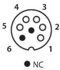
text_image
4 3 5 2 6 1 NC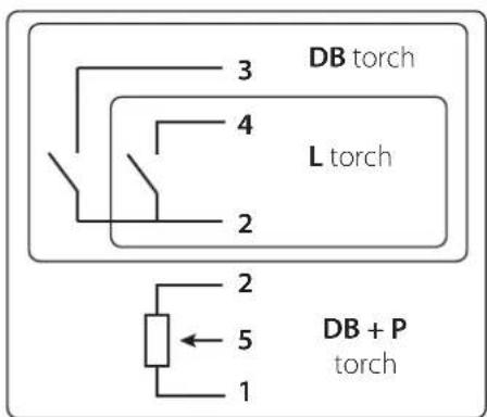
text_image
DB torch L torch 2 3 4 2 5 1 DB + P torchtext_image
TIG ACMIX #1.6 STD 2T Remote Control Pedal R.C. Hand R.C. Automation - Connect 5 None OK I = 135 A \=0.3 sWAARSCHUWING - VEILIGHEIDSINSTRUCTIES
ALGEMENE INSTRUCTIES

INTERFACE HUMAN MACHINE (IHM) (FIG-2)
text_image
MMA PRO MMA PRO OPTIONS I 250 % 40 % 60 + I = 250 A U = 30 V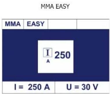
text_image
MMA EASY MMA EASY I = 250 A U = 30 VPRO en EASY mode opties
| % HotStart % ArcForce Omgekeerde polariteit | |||
| MODE EASY (40%) (40%) | |||
| MODE PRO 0 + 100% 0 - 100% X | |||
ADVIEZEN INSTELLING
- ArcForce
text_image
TIG | DC | μ1.6 | STD | 2T DC I = 160 A \t = 3.0 sTIG DC STD
text_image
TIG DC μ1.6 PLS 2T DC I = 160 A t = 3.0 sTIG DC PULS
• TIG DC STANDAARD
I_Koud = 50%, koude stroom = 50% x 100A = 50A.
text_image
TIG AC 1.6 STD 2T I = 160 A t = 3.0 sTIG AC STD TIG AC PULS
text_image
TIG AC 1.6 PLS 2T I = 160 A t = 3.0 s• TIG AC STANDAARD
text_image
Simple diagram with a plus sign and a minus sign on a horizontal line, possibly indicating polarity or subtraction.Balans : 20% Maximale inbranding 50 % 60% Maximale voorbewerking
natural_image
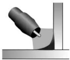
Close-up of a mechanical component with a pointed tip and angled edge, no visible text or symbolsHoge frequentie Lage frequentie
natural_image
Close-up of a mechanical component with a pointed tip and curved surface (no text or symbols visible)• TIG AC PULS
text_image
TIG | DC | μ1.6 | SPOT | 2T DC I = 100 A GraphTIG DC SPOT TIG AC SPOT
text_image
TIG AC μ1.6 SPOT 2T I=100 A GraphInstellingen en opties
text_image
TIG DC 81.6 TACK 2T DC I = 100 A GraphInstellingen en opties
text_image
P L DB 1 5 torch 2 4 L torch 2 3 DB torch
text_image
4 3 5 2 6 1 NC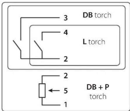
text_image
3 DB torch 4 L torch 2 2 5 DB + P torch 1text_image
TIG ACMIX #1.6 STD 2T Remote Control Pedal R.C. Hand R.C. Automation - Connect 5 None OK I = 135 A \=0.3 s3- Kies uw bediening
Aansluitingen
text_image
MMA | PRO | OPTIONS | I 250 A % 40 60 + I = 250 A U = 30 VMMA EASY
text_image
MMA EASY I A 250 I = 250 A U = 30 V| Arc Force PA PF PE | |||
| Rutilo 40% 20% 0% | |||
| Basico 60% 60% 20% | |||
| Cellulosico | 80% | - | 50% |
text_image
TIG | DC | μ1.6 | STD | 2T DC I = 160 A \t = 3.0 sTIG DC STD
text_image
TIG DC g1.6 PLS 2T DC I = 160 A \t = 3.0 sTIG DC PULSATO
• TIG DC STANDARD
text_image
TIG | AC | 1.6 | STD | 2T I = 160 A \t = 3.0 sTIG AC STD TIG AC PULSATO
text_image
TIG | AC | ∅1.6 | PLS | 2T I = 160 A ∪t = 3.0 s• TIG AC STANDARD
text_image
Simple diagram with a plus sign and a minus sign on a horizontal line, possibly indicating polarity or subtraction.
natural_image
Close-up of a mechanical component with a metallic tip, possibly a tool or bracket, interacting with a surface (no text or symbols visible)natural_image
Close-up of a mechanical component with a metallic handle and curved surface (no text or symbols visible)• TIG AC PULSATO
text_image
TIG DC μ1.6 SPOT 2T DC I = 100 A GraphTIG DC SPOT TIG AC SPOT
text_image
TIG AC μ1.6 SPOT 2T I = 100 A Graphtext_image
TIG DC B1.6 TACK 2T DC I = 100 A Graphtext_image
P L DB 1 5 2 P torch 4 L torch 3 DB torch
text_image
4 3 5 2 6 1 NC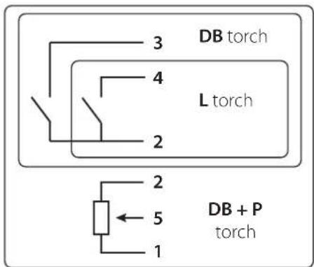
text_image
3 DB torch 4 L torch 2 2 5 1 DB + P torchtext_image
TIG ACMIX #1.6 STD 2T Remote Control Pedal R.C. Hand R.C. Automation - Connect 5 None OK I = 135 A \=0.3 stext_image
Technical diagram of an electronic device with numbered components and exploded view, labeled with parts 1 through 22.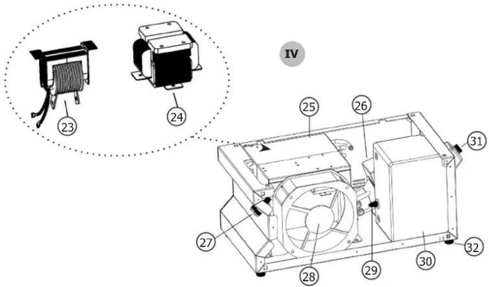
text_image
IV 23 24 25 26 31 27 28 29 30 32PIÈCES DE RECHANGE / SPARE PARTS / ERSATZTEILE / PIEZAS DE REPUESTO / ЗАПАСНЫЕ ЧАСТИ / RESERVE ONDERDELEN / PEZZI DI RICAMBIO
| II | ||
| 1 | Bouton noir ∅28mm + capuchon / Black knob ∅28mm + cap / Schwarzer Knauf ∅28mm + Kappe / Botón negro ∅28mm + tapa / Черная ручка ∅28mm + колпачок / Zwarte knop ∅28mm + dop / Manopola nera ∅28mm + cappuccio | 73020 |
| 2 Carte IHM / Control circuit board / Display Platine 97096C | ||
| 3 | Douille femelle Texas 50 / Female texas connection 50 / Texasanschluss 50 | 51461 |
| 4 | Faisceau connectique commande à distance / Remote control connection / Anschluss Fernregler | 71508 |
| 5 Connecteur torche / Torch connection / Anschluß Brennertasterleitung 51120 | ||
| 5a Connecteur FIL mâle fiche / Male connector 7 pins 51119 | ||
| 6 Coupleur gaz BSP20 / BSP20 gas connection / BSP20 Schutzgasanschluss 55090 | ||
| 6a | Included : Connecteur mâle sans obturateur/ Quick release male gas connector/ Schnellverschluß brennerseitig | 71706 |
| 7 Commutateur 2P Tri / 2P Tri switch / Ein/Aus-Schalter 95570 | ||
| 8 | Cordon secteur 3P + Terre 1,5mm ^2 / Mains power lead 3ph with 1,5mm ^2 earth connection / 1,5mm ^2 Netzkabel 3P + Erde | 21485 |
| 9 Porte fusible IP68 / IP68 fuse holder / IP68 Netzsicherungshalter 51387 | ||
| 9a Fusible / Fuse 51401 | ||
| 10 Electrovanne 2 voies 24V / 24V double solenoid valve / 24 V Doppelmagnetventil 71542 | ||
| III | ||
| 11 Circuit SMI primaire / Primary IMS / primäres Leistungsteil 97260 | ||
| 12 Pont de diode / Diode bridge / Diodenbrücke 64457 | ||
| 13 Circuit primaire / Primary circuit board / Primärplatine | 97044C | |
| 14 Circuit principal / Main circuit board / Hauptplatine | 97077C | |
| 15 Carte groupe froid / Liquid cooling system circuit board / Platine Wasserkühlgerät | 97167C | |
| 16 Circuit HF / HF circuit board / HF Platine | 97108C | |
| 17 Circuit alimentation auxiliaire / Auxiliary power supply circuit board / Platine Hilfsspannungsversorgung | 97227C | |
| 18 Circuit microcontroller / Microcontroller circuit board / Platine Mikroprozessor | 97076C | |
| 19 Circuit de commande à distance / Remote control circuit board / Platine Fernregelung | 97206C | |
| 20 Module IGBT / IGBT module / IGBT Modul | 52202 | |
| 21 Circuit secondaire / Secondary circuit board / Sekundärplatine | 97347C | |
| 22 Transformateur de puissance / Power transformer / Leistungstransformator 63702 | ||
| IV | ||
| 23 Transformateur HF / HF transformer / HF Transformator 63700 | ||
| 24 Self DC / Self DC / Drossel 96048 | ||
| 25 Condenseur / Condenser / Kondensator 71753 | ||
| 26 Pompe 10L/min 400V 50/60 Hz / 10L/min 400V 50/60 Hz pump / Kühlmittelpumpe 10L/m 400V 50/60Hz 71744 | ||
| 27 Coupleur gaz BSP21 / BSP21 gas coupler / BSP21 Schutzgaskupplung 71317 | ||
| 28 Ventilateur 400V 50/60 Hz / 400V 50/60 Hz fan / 400V 50/60Hz Ventilator 51003 | ||
| 29 Capteur de niveau d'eau / Water level sensor / Kühlmittelsensor 71766 | ||
| 30 Réservoir 5,5L / 5.5l tank / 5,5L Tank 90593 | ||
| 31 Bouchon du réservoir / Tank cap / Tankdeckel 71334 | ||
| 32 Pied butée Diam 25mm / rubber feet 25mm diameter / Gummifüße, Durchmesser 25mm 71143 | ||
SCHÉMA ÉLECTRIQUE / CIRCUIT DIAGRAM /SCHALTPLAN/ DIAGRAMA ELECTRICO /ЭЛЕКТРИЧЕСКАЯ СХЕМА / ELEKTRISCHE SCHEMA / SCEMA ELETTRICO
text_image
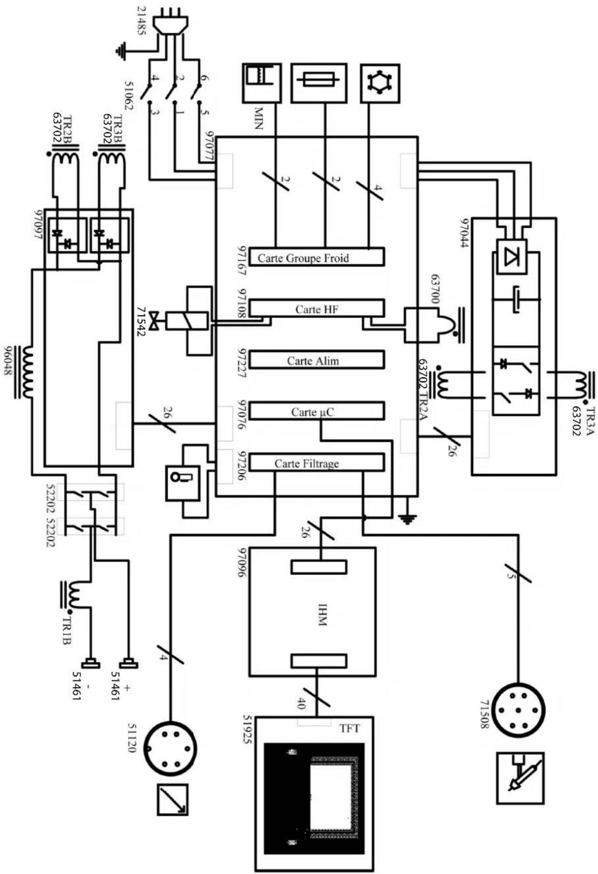
21485 51062 TR2B 63702 TR3B 63702 97097 97077 MIN 4 2 1 6 5 97077 Carte Groupe Froid 97167 97108 Carte HF 97044 63700 63702 TR2A TR3A 63702 97048 71542 Carte Alim 97227 97076 Carte μC 97206 Carte Filtrage 26 9706 IHM 40 51925 TFT TR1B 51461 51461 51120 52202 52202SPÉCIFICATIONS TECHNIQUES / TECHNICAL SPECIFICATIONS / TECHNISCHE DATEN / ESPECIFICACIONES TÉCNICAS / TEXНИЧЕСКИЕ СПЕЦИФИКАЦИИ / TECHNISCHE GEGEVENS / SPECIFICHE TECNICHE
| 250 AC/DC | |||
| Primaire / Primary / Primär / Primario / Первичka / Primaire / Primario / Podstawowy | |||
| Tension d'alimentation / Power supply voltage / Stromversorgung / Tensión de red eléctrica / Напряжение питания / Voedingsspanning / Tensione di alimentazione / Napięcie zasiliania | 400 V +/- 15% | ||
| Fréquence secteur / Mains frequency / Netzfrequenz / Frecuencia / Частота сети / Frequentie sector / Frequenza settore / Częstotliwość sieci zasiliania | 50 / 60 Hz | ||
| Nombre de phases / Number of phases / Anzahl der Phasen / Número de fases / Количество фаз / Aantal fasen / Numero di fase / Liczba faz | 3 | ||
| Fusible disjoncteur / Fuse / Sicherung / Fusible disyuntor / Fusible disyuntor / Плавкий предохранитель прерывателя / Zekering hoofdschakelaar / Fusibile disgiuntore / Wyłącznik bezpieczników | 16 A | ||
| Courant d'alimentation effectif maximal I1eff / Maximum effective supply current I1eff / Corriente de alimentación efectiva máxima I1eff / Maximale effectieve voedingsstroom I1eff / Corrente di alimentazione effettiva massima I1eff / Maksymalny efektywny prąd zasilania I1eff | 13 A | ||
| Courant d'alimentation maximal I1max / Maximum supply current I1max / Corriente de alimentación máxima I1max / Maximale voedingsstroom I1max / Corrente di alimentazione massima I1max / Maksymalny prąd zasilania I1max | 20 A | ||
| Section du cordon secteur / Mains cable section / Sectie netsnoer / Sección del cable de alimentación / Sezione del cavo di alimentazione / Odcinek przewodu zasilającego | 4 x 1.5 mm2 | ||
| Puissance active maximale consommée / Maximum active power consumed / Consumo máximo de energía activa / Maximale actieve verbruikte vermogen / Potenza attiva massima consumata / Maksymalny pobór mocy czynnej | 9740 W | ||
| Consommation au ralenti / Idle consumption / Consumo en ralentizado / Stationair verbruik / Consumo al minimo / Zużycie na biegu jałowym | 28.9 W | ||
| Rendement à I2max / Efficiency at I2max / Eficiencia a I2máx / Rendement bij I2max / Efficienza a I2max / Sprawność przy I2max | 80 % | ||
| Facteur de puissance à I2max (λ) / Power factor at I2max (λ) / Factor de potencia a I2max (λ) / Inschakelduur bij I2max (λ) / Ciclo di potenza a I2max (λ) / Współczynnik mocy przy I2max (λ) | 0.67 | ||
| Classe CEM / EMC class / Classe CEM / Klasse CEM / Classe CEM / Klasa EMC A | |||
| Secondaire / Secondary / Sekundär / Secundario / Вторичка / Secondair / Secondario / Zapasowy | MMA | TIG | |
| Tension à vide / No load voltage / Leerlaufspannung / Tensión al vacío / Напряжение холостого хода / Nullastspanning / Tensione a vuoto / Napięcie próźniowe | 85 V | ||
| Nature du courant de soudage / Type of welding current / Tipo de corriente de soldadura / Type lasstroom / Tipo di corrente di saldatura / Rodzaj prądu spawania | AC / DC | ||
| Modes de soudage / Welding modes / Modos de soldadura / Lasmodules / Modalità di saldatura / Tryby spawania MMA, TIG | |||
| Courant de soudage minimal / Minimum welding current / Corriente mínima de soldadura / Minimale lasstroom / Corrente mínima di saldatura / Minimalny prąd spawania | 5 A | ||
| Tension crête do dispositif d'amorçage manuel (EN60974-3) / Manual striking system's maximum voltage (EN60974-3) / Spitzenspannung des manuellen Starterätes (EN60974-3) / Tensión pico del dispositivo de cebado manual (EN60974-3) / Пиковое напряжение механизма ручного поджига (EN60974-3) / Piekspanning van het handmatige startysteem (EN60974-3) / Tensione di picco del dispositivo di innesco manuale (EN60974-3) / Napięcie szczytowe urządzenia do rozruchu ręczneta (EN60974-3) | 9 kV | ||
| Courant de sortie nominal ( I_2 ) / Normal current output ( I_1 ) / nominaler Ausgangsstrom ( I_2 ) / Corriente de salida nominal (I2) / Номинальный выходной ток (I2) / Nominale uitgangsstroom (I2) / Corrente di uscita nominale (I2) / Nominalny prąd wyjściowy (I2) | 10 A - 250 A 5 A | - 250 A | |
| Tension de sortie conventionnelle ( U_1 ) / Conventional voltage output ( U_1 ) / entsprechende Arbeitsspannung ( U_1 ) / Tensión de salida convencional (U2) / Условное выходные напряжения (U2) / Conventionele uitgangsspanning (U2) / Tensione di uscita convenzionale (U2) / Konwencjonalne napięcie wyjściowe (U2) | 20.4 V - 30V 10 | 2 V - 20 V | |
| - Facteur de marche à 40°C (10 min)*Norme EN60974-1.- Duty cycle at 40°C (10 min)*Standard EN60974-1.- Einschaltdauer @ 40°C (10 min)*EN60974-1 -Norm. | - Ciclo de trabajo a 40°C (10 min)*Norma EN60974-1- ПВ% при 40°C (10 мин)*Norma EN60974-1.- Inschakelduur bij 40°C (10 min)*Norm EN60974-1.- Cykl pracy w 40°C (10 min)*Norma EN60974-1. | Imax 40 % 60 %60% 230 A 250 A100% 200 A 200 A | |
| Température de fonctionnement / Functionning temperature / Betriebstemperatur / Temperatura de funcionamiento / Рабочая температура / Gebruikstemperatuur / Temperatura di funzionamento / Temperatura urządzenia podczas pracy | -10 à +40 °C | ||
| Température de stockage / Storage temperature / Lagerungstemperatur / Temperatura de almacenaje / Температура хранения / Bewaartemperatuur / Temperatura di stoccaggio / Temperatura przechowywania | -20 à +55 °C | ||
| Degré de protection / Protection level / Schutzgrad / Grado de protección / Степень защиты / Beschermingsklasse / Grado di protezione / Stopień ochrony | IP23 | ||
| Classe d'Isolation minimale des enroulements / Minimum coil insulation class / Clase mínima de aislamiento del bobinado / Minimale isolatieklasse omwikkelingen / Clase mínima di isolamento degli avvolgimenti / Minimalna klasa izolacji okablowania | B | ||
| Dimensions (Lxlxh) / Dimensions (Lxlxh) / Abmessung (LxBxH) / Dimensiones (Lxlxh) / Размеры (ДхШхВ) / Afmetingen (Lxlxh) / Dimensioni (Lxlxh) / Wymiary (DxSxW) | 80 x 48 x 75 cm | ||
| Poids / Weight / Gewicht / Peso / Bec / Gewicht / Peso / Waga | 58 kg | ||