Neopulse 320 C - Welding machine GYS - Free user manual and instructions
Find the device manual for free Neopulse 320 C GYS in PDF.
| Product type | Professional three-phase welding machine |
| Brand | GYS |
| Model | Neopulse 320 C |
| Welding processes | MIG/MAG (GMAW/FCAW), TIG DC (GTAW), MMA (SMAW) |
| Current range (MMA) | 5 – 320 A (depending on electrode) |
| Current range (MIG/MAG) | 20 – 320 A |
| Current range (TIG) | 5 – 320 A |
| Supply voltage | 400 V +/- 15% three-phase 50/60 Hz (32 A plug EN 60309-1) |
| Duty cycle (40°C, 10 min cycle) | At 320 A: 35% (MIG/MAG); at 320 A: 35% (MMA); at 320 A: 35% (TIG) |
| Wire diameters (MIG/MAG) | Steel: 0.6 – 1.2 mm; Stainless: 0.8 – 1.2 mm; Aluminum: 0.8 – 1.2 mm; CuSi/CuAl: 0.8 – 1.2 mm; No Gas: 0.9 – 1.6 mm |
| Accepted spools | 200 and 300 mm |
| Cooling type | Intelligent ventilation (speed management) |
| Protection rating | IP23 |
| Operating temperature | -10 °C to +40 °C |
| Storage temperature | -20 °C to +55 °C |
| Allowable humidity | <= 50% at 40 °C, <= 90% at 20 °C |
| Max. altitude | 1000 m |
| Weight (estimated) | Approximately 32 kg (without accessories) |
| Dimensions (approx.) | 700 x 300 x 500 mm (L x W x H) |
| User interface | LCD screen with knobs, push buttons; Easy, Expert, Advanced modes |
| Special functions | Synergic, Pulse, Spot, E-TIG, Hot Start, Arc Force, Anti-Sticking, Traceability, JOB (500+), Quick-Load |
| Connectivity | USB, analog and digital RC connectors, Euro connector, SMC option |
| Included accessories | Steel double groove rollers 1.0/1.2, 32 A plug, pressure regulator, MIG/MAG torch (depending on version) |
| Maintenance | Dusting with blow gun, annual connection check by qualified personnel |
Frequently Asked Questions - Neopulse 320 C GYS
User questions about Neopulse 320 C GYS
0 question about this device. Answer the ones you know or ask your own.
Ask a new question about this device
Download the instructions for your Welding machine in PDF format for free! Find your manual Neopulse 320 C - GYS and take your electronic device back in hand. On this page are published all the documents necessary for the use of your device. Neopulse 320 C by GYS.
USER MANUAL Neopulse 320 C GYS
FR 02-03/4-21/124-131
EN 02-03/22-38/124-131
DE 02-03/39-55/124-131
ES 02-03/56-72/124-131
RU 02-03/73-89/124-131
NL 02-03/90-106/124-131
IT 02-03/107-123/124-131
NEOPULSE 320 C
INSTALLATION - FONCTIONNEMENT PRODUIT
INTERFACE HOMME-MACHINE (IHM)

IHM
Standard (courant constant)
E-TIG (energie constante)
CHOIX DU DIAMÉTRE DE L'ÉLECTRODE
ANOMALIES, CAUSES, REMÉDES
CONDITIONS DE GARANTIE
WARNING - SAFETY INSTRUCTIONS
GENERAL INSTRUCTIONS
These instructions must be read and understood before using the machine. Any modification or maintenance that is not specified in the manual must not be carried out.
The manufacturer will not be held responsible for any damage to persons or property caused by the failure to follow this product's user manual instructions.
In case of problems or queries, please consult a qualified tradesperson to correctly install the product.
ENVIRONMENT
This equipment should only be used for welding operations performed within the limits indicated on the information panel and/or in this manual. These safety guidelines must be observed. The manufacturer cannot be held responsible in cases of improper or dangerous use.
The machine must be set up somewhere free from dust, acid, flammable gases or any other corrosive substances. This also applies to the machine's storage. Operate the machine in an open or well-ventilated area.
Temperature range:
Operate between -10 and +40^ (+14 and +104°F).
Store between -20 and +55^ (-4 and 131°F).
Air humidity: Less than or equal to 50% at 40^ (104^) Lower than or equal to 90% at 20^ (68^)
Altitude: Up to 1,000m above sea level (3,280 feet).
PROTECTING YOURSELF AND OTHERS
Arc welding can be dangerous and cause serious injury or death.
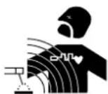
Welding exposes people to a dangerous heat source, arc light, electromagnetic fields (be aware of those wearing pacemakers), risk of electrocution, loud noises and fumes.
To protect yourself and others, please observe the following safety instructions:

To protect yourself from burns and radiation, wear insulating, dry and fireproof clothing without lapels. Ensure the clothing is in good condition and that covers the whole body.

Wear gloves that ensure electrical and thermal insulation.

Use welding protection and/or a welding helmet with a sufficient level of protection (depending on the specific use). Protect your eyes during cleaning operations. Contact lenses are specifically forbidden. It may be necessary to section off the welding area with fireproof curtains to protect the area from arc radiation and hot spatter. Advise people in the welding area not to stare at the arc rays or molten material and to wear appropriate protective clothing.

Wear noise protection headphones if the welding process becomes louder than the permissible limit (this is also applicable to anyone else in the welding area).
Keep your hands, hair and clothing away from moving parts (for example, the fans). Never remove the cooling unit housing protections when the welding power source is live, the manufacturer cannot be held responsible inthe event of an accident.
The newly welded parts are hot and can cause burns when handled. When maintenance work is carried out on the torch or electrode holder, ensure that it is sufficiently cold by waiting at least 10 minutes before carrying out any work. The cooling unit must be switched on when using a water-cooled torch to ensure that the liquid cannot cause burns. To protect people and property, it is important to properly secure the work area before leaving.
WELDING FUMES AND GAS

The fumes, gases and dusts emitted during welding are harmful to health. Sufficient ventilation must be provided and an additional air supply may be required. A n air-fed mask could be a solution in cases where there is insufficient ventilation. Check that the suction is functioning effectively by checking it against safety standards.
Caution: when welding in small areas requires supervision from a safe distance. In addition, the welding of certain materials containing lead, cadmium, zinc, mercury or even beryllium can be particularly harmful. Remove any grease from the parts before welding.
Gas cylinders should be stored in open or well-ventilated areas. They should be kept in an upright position and kept on a cart or trolley. Welding should not be undertaken near grease or paint.
FIRE AND EXPLOSION RISKS

Fully protect the welding area, flammable materials should be kept at least 11 metres away. Fire fighting equipment should be present in the vicinity of welding operations.
Beware the expulsion of hot spatter or sparks, even through cracks, which can cause fires or explosions. Keep people, flammable objects and pressurised containers at a safe distance.
Do not weld in closed containers or tubes. If they are open, remove any flammable or explosive materials (oil, fuel, etc.) before welding. Grinding work must not be directed towards the source of the welding current or towards any flammable materials.
GAS CYLINDERS

Gas escaping from the cylinders can cause suffocation if it becomes concentrated in the welding area (ventilate well). Transporting the machine must be done safely: gas cylinders must be closed and the welding power source turned off. They should be stored upright and supported to reduce the risk of falling.
Tightly close the bottle between uses. Beware of temperature changes and sun exposure.
The bottle should not come into contact with flames, electric arcs, torches, earth clamps or any other sources of heat.
Keep away from electrical and welding circuits and never weld a pressurised cylinder.
When opening the cylinder valve, keep your head away from the valve and ensure that the gas being used is suitable for the welding process.
ELECTRICAL SAFETY

The electrical network used must be earthed. Use the recommended fuse size chosen from the information table. Electric shocks can cause serious direct and indirect accidents or even death.
Never touch live parts connected to the live current, either inside or outside the power source casing unit (torches, clamps, cables, electrodes), as these items are connected to the welding circuit.
Before opening the welding machine's power source, disconnect it from the mains and wait two minutes to ensure that all the capacitors have fully discharged.
Do not touch the torch or the electrode holder and the earth clamp at the same time.
If the cables or torches become damaged, they must be replaced by a qualified and authorised person. Measure the length of cable according to its use. Always wear dry, good quality clothing to insulate yourself from the welding circuit. Alongside this, wear well-insulated footwear in all working environments.
EMC CLASSIFICATION

This Class A equipment is not intended for domestic use where electrical power is supplied from the low-voltage mains system. Ensuring electromagnetic compatibility may be difficult at these sites due to conducted, as well as radiated, radio frequency interference.
This equipment complies with IEC 61000-3-11.
This equipment does not comply with IEC 61000-3-12 and is designed to be plugged into private, low voltage, power supply networks. It is intended to be connected to the public mains supply only at medium or high voltage level. If connected to a public, low voltage, power supply network, it is the installer or user's responsibility to ensure that the equipment can be properly connected by checking with the mains grid operator.
ELECTROMAGNETIC INTERFERENCES
An electric current passing through any conductor produces localised electric and magnetic fields (EMF). The welding current produces an electromagnetic field around the welding circuit and the welding equipment.
Electromagnetic fields (EMFs) can interfere with some medical devices, for example pacemakers. Protective measures should be taken for those with medical, implanted devices. For example, restricted access for onlookers or an individual risk assessment for welders.
All welders should use the following guidelines to minimise exposure to the welding circuit's electromagnetic fields:
- position the welding cables together - if possible, securing them with a clamp,
- position yourself (head and body) as far away from the welding circuit as possible,
-
never wrap the welding cables around your body,
-
do not position yourself between the welding cables and keep both welding cables on your same side,
- connect the return cable to the workpiece, as close as possible to the area to be welded,
- do not work next to, sit or lean on the source of the welding current,
- do not weld while transporting the source of the welding current or wire feeder.

Pacemaker users should consult a doctor before using this equipment.
Exposure to electromagnetic fields during welding may have other health effects that are not yet known.
RECOMMENDATIONS FOR ASSESSING THE WELDING AREA AND EQUIPMENT
General Information
It is the user's responsibility to install and use the arc welding equipment according to the manufacturer's instructions. If electromagnetic disturbances are detected, it is the user's responsibility to resolve the situation using the manufacturer's technical support. In some cases, this corrective action may be as simple as earthing the welding circuit. In other cases, it may be necessary to construct an electromagnetic shield around the welding current source and around the entire workpiece by setting up input filters. In any case, electromagnetic interference should be reduced until it is no longer an inconvenience.
Assessing the welding area
Before installing arc welding equipment, the user should assess the potential electromagnetic problems in the surrounding area. The following should be taken into account:
a) the presence of power, control, signal and telephone cables above, below and next to the arc welding equipment,
b) radio and television receivers and transmitters,
c) computers and other control equipment,
d) critical safety equipment, e.g. the protection of industrial equipment,
e) the health of nearby persons, e.g. those using of pacemakers or hearing aids,
f) the equipment used for calibrating or measuring,
g) the protection of other surrounding equipment.
The operator has to ensure that the devices and equipment used in the same area are compatible with each other. This may require further protective measures;
h) the time of day when welding or other activities are to take place.
The size of the surrounding area to be taken into account will depend on the building's structure and the other activities taking place there. The surrounding area may extend beyond the boundaries of the premises.
Assessment of the welding equipment
In addition to the assessment of the surrounding area, the arc welding equipment's assessment can be used to identify and resolve cases of interference. It is appropriate that the assessment of any emissions should include in situ procedures as specified in Article 10 of CISPR 11. In situ procedures can also be used to confirm the effectiveness of mitigation measures.
GUIDELINES ON HOW TO REDUCE ELECTROMAGNETIC EMISSIONS
a. The mains power grid: Arc welding equipment should be connected to the mains power grid according to the manufacturer's recommendations. If any interference occurs, it may be necessary to take additional precautionary measures such as filtering the mains power supply. Consider protecting the power cables of permanently installed, arc welding equipment within a metal pipe or a similar casing. The power cable should be protected along its entire length. The protective casing should be connected to the welding machine's power source to ensure good electrical contact between the protective pipeline and the welding machine's power source housing.
b. The maintenance of arc welding equipment: Arc welding equipment should be subject to routine maintenance as recommended by the manufacturer. All access points, service openings and bonnets should be closed and properly locked when the arc welding equipment is in use. The arc welding equipment should not be modified in any way, except for those modifications and adjustments mentioned in the manufacturer's instructions. The spark gap of arc starters and stabilisers should be adjusted and maintained according to the manufacturer's recommendations.
c. Welding cables: Cables should be as short as possible, placed close together either near or on the ground.
d. Equipotential bonding: Consideration should be given to the joining of all metal objects in the surrounding area. However, metal objects connected to the workpiece increase the risk of electric shocks to the user if they touch both these metal parts and the electrode. The user should be isolated from such metal objects.
e. Earthing the workpiece: In cases where the part to be welded is unearthed for electrical safety reasons or due to its size and location, such as ship hulls or structural steel buildings, an earthed connection can reduce emissions in some cases, although not always. Care should be taken to avoid the earthing of parts which could increase the risk of injury to users or damage to other electrical equipment. If necessary, the workpiece's connection should be earthed directly, but in some countries where a direct connection is not allowed, the connection should be made with a suitable capacitor chosen according to national regulations.
f. Protection and protective casing: The selective protection and encasing of other cables and equipment in the surrounding area may limit interference problems. The safeguarding of the entire welding area may be considered for special applications.
THE TRANSPORTING AND MOVING OF THE MACHINE'S POWER SOURCE

The machine is fitted with handle(s) to facilitate transportation. Be careful not to underestimate the machine's weight. The handle(s) cannot be used for slinging.
Do not use the cables or torch to move the welding power source. It should be transported in an upright position.
Do not carry or transport the power source overhead of people or objects.
Never lift a gas cylinder and the welding power source at the same time. Their transport requirements are different.
It is advisable to remove the wire spool before lifting or transporting the welding power source.
SETTING UP THE EQUIPMENT
- Place the welding power source on a floor with a maximum inclination of 10^ .
- Provide sufficient space to ventilate the welding power source and access the controls.
- Do not use in an area with conductive metal dust.
- The welding power source should be protected from heavy rain and not exposed to direct sunlight.
The equipment has an IP23 protection rating which means: - its dangerous parts are protected from being entered by objects greater than 12.5mm and,
- it is protected against rain falling up to 60^ from the vertical.
The equipment can be used outside in accordance with the IP23 protection certification.

Stray welding currents can destroy earthing conductors, damage electrical equipment and devices and cause component parts to overheat leading to fires.
- All welding connections must be firmly secured and regularly checked!
- Make sure that the item's attachment is firm and secure, without any electrical problems!
- Join together or suspend any electrically conductive parts of the welding source such as the frame, trolley and lifting systems so that they are insulated!
- Do not place other equipment such as drills or grinding devices etc. on the welding source, trolley, or lifting systems unless they are insulated!
- Always place welding torches or electrode holders on an insulated surface when not in use!
Power cables, extension cables and welding cables should be fully unwound to avoid overheating.

The manufacturer assumes no responsibility for damage to persons or objects caused by improper and dangerous use of this equipment.
MAINTENANCE / RECOMMENDATIONS


- Maintenance should only be carried out by a qualified person. Annual maintenance is recommended.
- Switch off the power supply by pulling the plug and wait two minutes before working on the equipment.. Inside the machine, the
voltages and currents are high and dangerous.
- Regularly remove the cover and blow out any dust. Take advantage of the opportunity to have the electrical connections checked with an insulated tool by a qualified professional.
Regularly check the condition of the power cord. If the power cable is damaged, it must be replaced by the manufacturer, the after sales service team or an equally qualified person to avoid any danger. - Leave the welding power source vents free for air intake and outflow.
- Do not use this welding power source for thawing pipes, recharging batteries/storage batteries or starter motors.
INSTALLATION - USING THE PRODUCT
Only experienced persons, authorised by the manufacturer, may carry out the installation. During installation, ensure that the power source is disconnected from the mains. Series or parallel power source connections are not allowed. It is recommended to use the welding cables supplied with the unit in order to obtain the best performance.
DESCRIPTION
This machine is a three-phase power source for semi-automatic, software-supported welding (MIG or MAG), coated electrode welding (MMA) and refractory electrode welding (TIG). It accepts 200 and 300mm diameter wire spools.
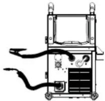
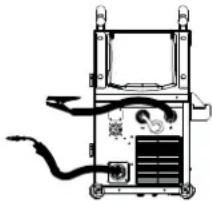
DESCRIPTION OF THE EQUIPMENT (I)
1-ON/OFF switch 10-Interface (MMI)
2-Gas connector 11-Digital RC connector (option ref.063938)
3-Cable gland (mains cable) 12- Analogue connector
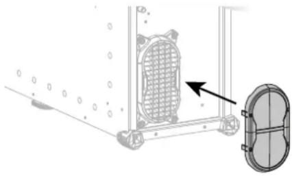
4-External grids 13-Euro connector
5- Reel support 14- polarity plug
6-USB connector 15- ^+ polarity plug
7-Rocker switch wire feed / gas purge 16-Polarity reversal cable
8-Wirefeed motor 17-SMC connection system (optional)
HUMAN-MACHINE INTERFACE (HMI)

Please read the Human Machine Interface (HMI) which forms part of the equipment's user literature.
POWER SWITCH
- This equipment is supplied with a 32 AEN 60309-1 socket and should only be used on a three phase, 400V (50-60 Hz), four wire, earthed electrical system. The actual absorbed current (I1eff) for optimal operating conditions is indicated on the equipment. Check that the power supply and its safeguards (fuses and/or circuit breakers) are compatible with the current required to use the machine. For optimum functionality in certain countries, it may be necessary to change the plug.
The power source is designed to operate at 400V + / - 15% . The machine will go into protection mode if the supply voltage falls below 330 Veff (rated insulation voltage) or goes above 490 Veff, (an error code will appear on the display screen). - To switch the machine on, turn the on/off switch (1-1) to position 1, whereas switching it off is done by turning the switch to position 0. Caution! Never disconnect the machine from the power supply while the machine is charging.
- Ventilation fan performance: This equipment is fitted with smart ventilation management system in order to minimise the noise made by the machine. The fans will adjust their speed according to usage and the surrounding temperature. They can be switched off in MIG or TIG mode.
CONNECTING TO A POWER SOURCE
This equipment can be operated with electric generators provided that the auxiliary power supply meets the following requirements:
- The voltage must be alternating with an RMS value of 400V + / - 15% and a peak voltage of less than 700V
- The frequency must be between 50 and 60Hz
It is vital to check these conditions as many generators produce high voltage peaks that can damage equipment.
USING EXTENSION LEADS
All extension leads must be of a suitable length and width that is appropriate to the equipment's voltage. Use an extension lead that complies with national safety regulations.
| Input voltage Length | Size of the extension cord (Length < 45m) |
| 400 V 4 mm² |
SETTING UP THE REEL

- Remove the nozzle (a) and contact tube (b) from your MIG/MAG torch.
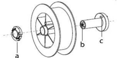
Open the power source's hatch.
- Position the reel on its holder
- Take into consideration the reel stands's drive lug (c). To fit a 200 mm reel, tighten the plastic reel holder (a) to the maximum.
- Adjust the brake wheel (b) to prevent the non-moving spool from tangling the wire when the welding stops. In general, do not overtighten, as this will cause the motor to overheat.
LOADING THE FILLER WIRE
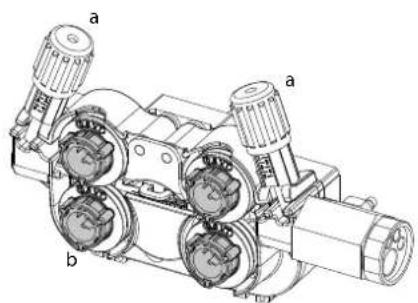
To change the rollers, do the following:
- Loosen the knobs (a) to the maximum and lower them.
- Unlock the rollers by turning the retaining rings (b) by a quarter turn.
- Fit the correct drive rollers for your use and lock the retaining rings in place.
The rollers supplied are double groove steel rollers (1.0 and 1.2).
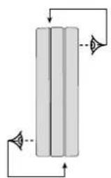
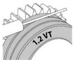
- Check the inscription on the roller to ensure that the rollers are suitable for the wire diameter and the wire material (for a 1.2 wire, use the 1.2 groove).
- Use V-grooved rollers for steel and other hard wires.
- Use U-grooved rollers for aluminium and other soft, alloyed wires.
: visible inscription on the roller (example: 1.2 VT)
→:groove to use
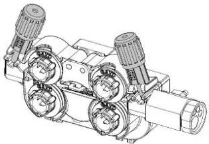
Do the following to install the filler wire:
- Loosen the dials to the maximum and lower them.
- Insert the wire, then close the motor reel and tighten the dials as shown.
- Operate the motor using the torch trigger or the manual wire feed button (I-6).

Notes:
- Too narrow a sheath can lead to unreeling issues and can lead to the overheating of the motor.
- The torch connection must also be properly tightened to prevent it from overheating.
- Ensure that neither the wire, nor the reel, touches the device's mechanism, otherwise there is a danger of short-circuiting the machine.
RISK OF INJURY FROM MOVING COMPONENTS
The reels have moving parts that can trap hands, hair, clothing or tools causing injuries!
- Do not touch rotating, moving or driving parts of the machine!
- Ensure that the housing covers or protective covers remain fully closed when in operation!
- Do not wear gloves when threading the filler wire or changing the filler wire reel.
SEMI-AUTOMATIC STEEL/STAINLESS STEEL WELDING (MAG MODE)
This machine can weld steel wire from 0.6 to 1.2mm and stainless steel wire from 0.8 to 1.2mm (II-A).
The machine is designed for use with 0.10mm steel wire ( 0.10/1.2 roller) as standard. The contact tip, the sheave groove and the welding torch sheath are designed for this use. Use a torch no longer than 3m to weld 0.6 diameter wire. The contact tip as well as the spools of the motorised wire feed roller should be replaced by a 0.6 grooved model (ref. (ref. 061859). In this case, position it so that the marking 0.6 is visible.
To do this using steel requires a specific welding gas (Ar+CO2). The amount of CO2 may vary depending on the type of gas used. Use 2% CO2 for stainless steel. It is necessary to connect a gas pre-heater to the gas cylinder when welding with pure CO2. For specific gas issues, please contact your gas distributor. The gas flow rate for steel is between 8 and 15 litres per minute depending on the surroundings.
SEMI-AUTOMATIC ALUMINIUM WELDING (MIG MODE)
The equipment can weld aluminium wire from 0.8 to 1.2mm (II-B).
The use of aluminium requires a specific, pure, argon gas (Ar). Seek advice from a gas distributor for a wide selection of gases. he gas flow rate of aluminium is between 15 and 25 l/min depending on the surrounding environment and the welder's experience.
The differences between steel and aluminium processing are as follows:
- Use specific rollers for aluminium welding.
- Put minimum pressure on the motorised reel's pressure rollers so as not to crush the thread.
- Use a capillary tube (to guide the wire between the motorised wire feeder rollers and the EURO connector) for steel/stainless steel welding only.
- Use a special aluminium torch. This aluminium torch has a Teflon coating to reduce friction. DO NOT cut away the coating at the tip of the connector! This coating is used to guide the wire from the rollers.
- Contact tips: use a SPECIAL aluminium contact tip that matches the wire's diameter.
When using red or blue sheathing (aluminium welding), it is recommended to use the 91151 (II-C) accessory. This stainless steel sheath guide improves the centering of the sheath and facilitates the flow of the wire.

Video
SEMI-AUTOMATIC WELDING IN CUSI AND CUAL (SOLDERING MODE)
The machine can weld CuSi and CuAl wire from 0.8 to 1.2mm
In the same way as with steel, a capillary tube must be set up and a torch with a steel sheath must be used. When braze welding, pure argon (Ar) should be used.
SEMI-AUTOMATIC «NO GAS» WIRE WELDING
This equipment can weld wire without gas protection (No Gas) from 0.9 to 1.6 mm. Welding flux-cored wire with a standard nozzle can lead to overheating and damage to the torch. Remove the original nozzle from your MIG-MAG torch.
CHOOSING A POLARITY
Polarity + Polarity -
Gas-shielded MIG/MAG welding generally requires positive polarity.
MIG/MAG welding without gas shielding (No Gas) generally requires negative polarity.
In any case, refer to the wire manufacturer's recommendations for the choice of polarity for your MIG-MAG torch.
GAS SUPPLY
- Fit a suitable pressure regulator to the gas cylinder. Connect it to the welding station with the pipe supplied. Attach the two hose clamps to prevent leaks.
- Ensure that the gas cylinder is held securely in place with a chain attached to the power source.
- Set the gas flow rate by adjusting the dial on the pressure regulator.
NB: To adjust the gas flow rate more easily, use the rollers on the motorised spool by pulling the trigger on the torch (loosen the brake wheel on the motorised reel so that no wire is drawn in). Maximum gas pressure: 0.5 MPa (5 bar).
This procedure does not apply to welding in «No Gas» mode.
RECOMMENDED COMBINATIONS
| (mm) | Current (A) Ø Wire (mm) Ø Nozzle (mm) Flow rate L/min | ||||
| MIG | 0.8-2 20-100 0 | 8 12 10-12 | |||
| 2-4 100-200 1 | 1.0 12-15 12-15 | ||||
| 4-8 200-300 1 | 1.0/1.2 | 15-16 15-18 | |||
| 8-15 | 300-500 1.2/1.6 | 16 18-25 | |||
| MAG | 0.6-1.5 | 15-80 | 0.6 | 12 | 8-10 |
| 1.5-3 80-150 0 | 8 12-15 10-12 | ||||
| 3-8 150-300 1 | 1.0/1.2 | 15-16 12-15 | |||
| 8-20 | 300-500 1.2/1.6 | 16 15-18 | |||
MIG/MAG(GMAW/FCAW)WELDING MODE
| Welding processes | ||||||||
| Settings | ADJUSTABLE SETTINGS | MANUAL | STD DYNAMIC | STD IMPACT | STD ROOT | COLD PULSE | PULSE | |
| Couple material/gas | - Fe Ar 25% CO2- ... | - | ✓ | ✓ | ✓ | ✓ | ✓ | Choice of the material to be welded.Pre-installed welding user settings |
| Wire diameter | Ø 0.6 > Ø 1.6 mm | ✓ | ✓ | ✓ | ✓ | ✓ | ✓ | Choice of wire diameter |
| ModulArc | OFF - ON | - | - | - | - | - | ✓ | Activating or deactivating the welding current's modulation(Double Pulse) |
| USING THE TRIG-GER | 2T, 4T | ✓ | ✓ | ✓ | ✓ | ✓ | ✓ | Choice of trigger welding management mode. |
| Spot welding mode | SPOT, DELAY | ✓ | ✓ | ✓ | ✓ | ✓ | - | Selecting spot welding mode |
| First Setting | Thickness Start-up Speed | - | ✓ | ✓ | ✓ | ✓ | ✓ | Choosing the main setting to be displayed (thickness of the workpiece, average welding current or wire speed). |
| Power | Hold Thermal coefficient | ✓ | ✓ | ✓ | ✓ | ✓ | ✓ | See «Power» section on the following pages. |
Access to some welding settings depends on the selected display mode: Settings/Display mode: Easy, Expert, Advanced. Refer to the HMI manual.
WELDING PROCESSES
For more information on GYS pre-installed user settings and welding processes, scan the QR code:

SPOT WELDING MODE
- SPOT WELDING
This welding mode allows the pre-assembly of parts before welding. Spot welding can be done manually using the trigger or timed with a predefined spot welding period. This spot welding makes reproduction and execution of non-oxidised weld points easier (accessible in the advanced menu).
- TIME LIMITS
This is a welding mode similar to SPOT welding but with predefined weld and dwell times, as long as the trigger is held down.
CONFIGURING THE SETTINGS
| Units | ||
| Wire speed | m/min | Amount of filler metal deposited and consequently the welding intensity and penetration. |
| Voltage V Control over the cord's width. | ||
| Self - Lessens the welding current | more or less. To be set according to the welding position. | |
| Pre-Gas s When the torch is bled | and the gas shield is created before ignition. | |
| Post-Gas s | Duration of the gas protection after the arc is extinguished. It protects the workpiece and the electrode from oxidation. | |
| Thickness mm | The pre-installed user settings (synergies) allow for a fully-automatic set-up. Working with different thicknesses automatically sets the appropriate thread tension and speed. | |
| Start-up A | The welding current is set according to the type of wire used and the material to be welded. | |
| Arc length | - | Used to adjust the distance between the end of the wire and the weld pool (tension adjustment). |
| Approach speed | % | Progressive yarn speed. Before priming, the wire moves slowly to create the first contact without jolting. |
| Hot Start | % & s | The Hot Start is an overcurrent used at the start that prevents the wire from sticking to the workpiece. The intensity (% of welding current) and the time (seconds) can be programmed. |
| Crater Filler | % | This idling bearing current is a phase after the current is lowered. The intensity (% of welding current) and the time (seconds) can be programmed. |
| Soft Start s | Gradual current increase. The current is controlled between the first contact and the welding process in order to avoid the possibility of violent ignitions or jolts. | |
| Uplope | s Upslope current | |
| Cold current | % | Second welding current known as a «cold» welding current. |
| Pulse frequency | Hz | Pulse frequency |
| Duty cycle | % | In pulsed mode, the hot current time is adjusted in relation to the cold current time. |
| Downslope | s Downslope current. | |
| Tack welding | s Set duration. | |
| Time between two points | s | Time between the end of a point (excluding Post-Gas) and the start of a new point (including Pre-Gas). |
| Burnback | s | Feature preventing the thread sticking to the bead. This is timed to coincide with the wire rising from the weld pool. |
Access to some welding settings depends on the welding process (Manual, Standard, etc.) and the selected display mode (Easy, Expert or Advanced). Refer to the HMI manual.
MIG/MAG WELDING CYCLES
Standard 2T process:
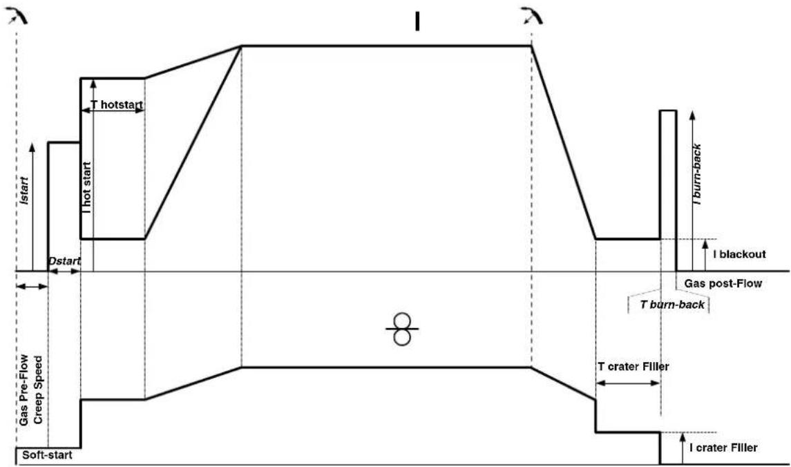
When the trigger is pulled, the pre-gas starts. When the wire touches the workpiece, a pulse initiates the arc and the welding cycle starts. When the trigger is released, the wire feeding stops and a current pulse cleanly cuts the wire, followed by the post-gas. As long as the post-gas has not finished, pressing the trigger will allow a quick restart of the weld (manual chain stitch) without going through the HotStart phase. A HotStart and/or a crater filler can be added to the cycle.
Standard 4T process:
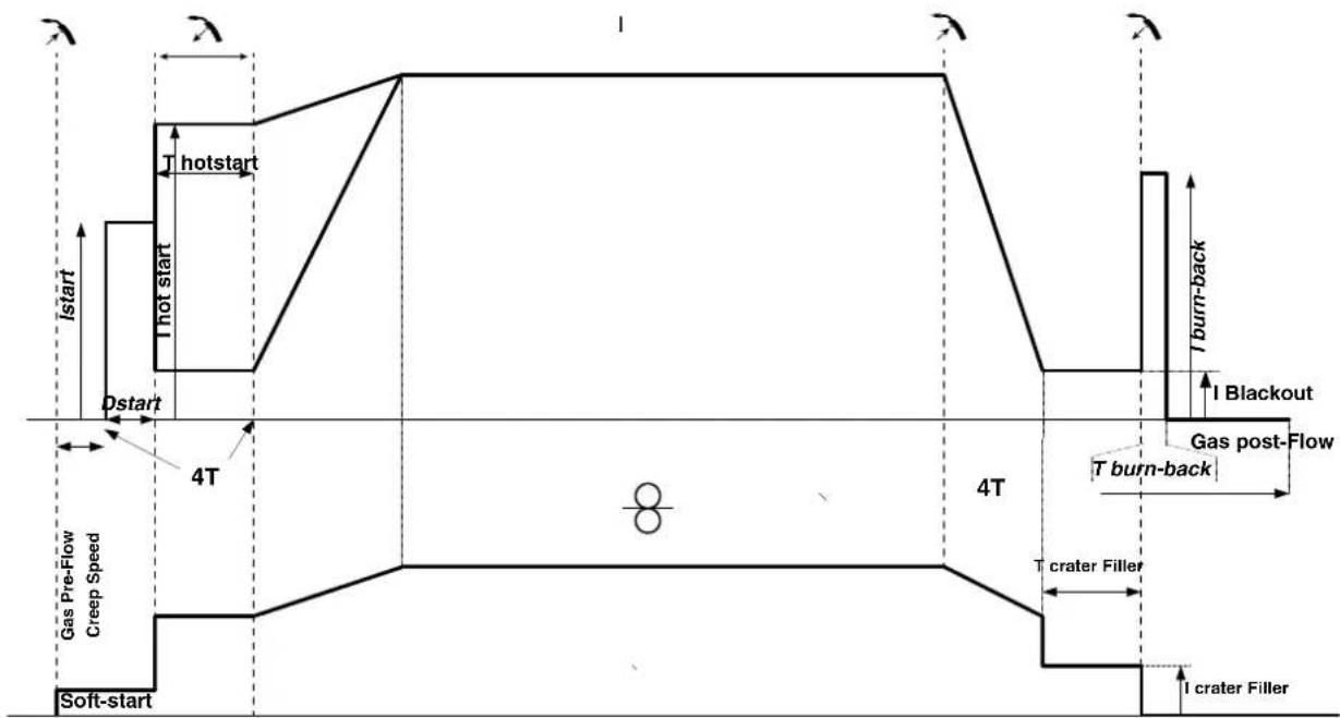
In a standard 4T process, the timing of pre-gas and post-gas is managed automatically. HotStart and crater filler are both controlled by the trigger.
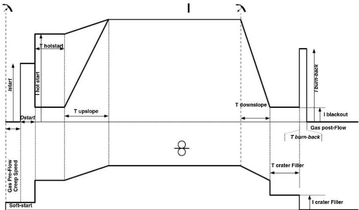
Pulsed 2T process:
When the trigger is pulled, the pre-gas starts. When the wire touches the workpiece, a pulse initiates the arc. Then, the machine starts with HotStart or upslope and finally, the welding cycle starts. When the trigger is released, the downslope initiates until it reaches crater fill. Then the STOP PEAK cuts the wire followed by the Post gas. Just as in Standard mode, the user can quickly restart the welding process during the post-gas phase without going through the HotStart phase.
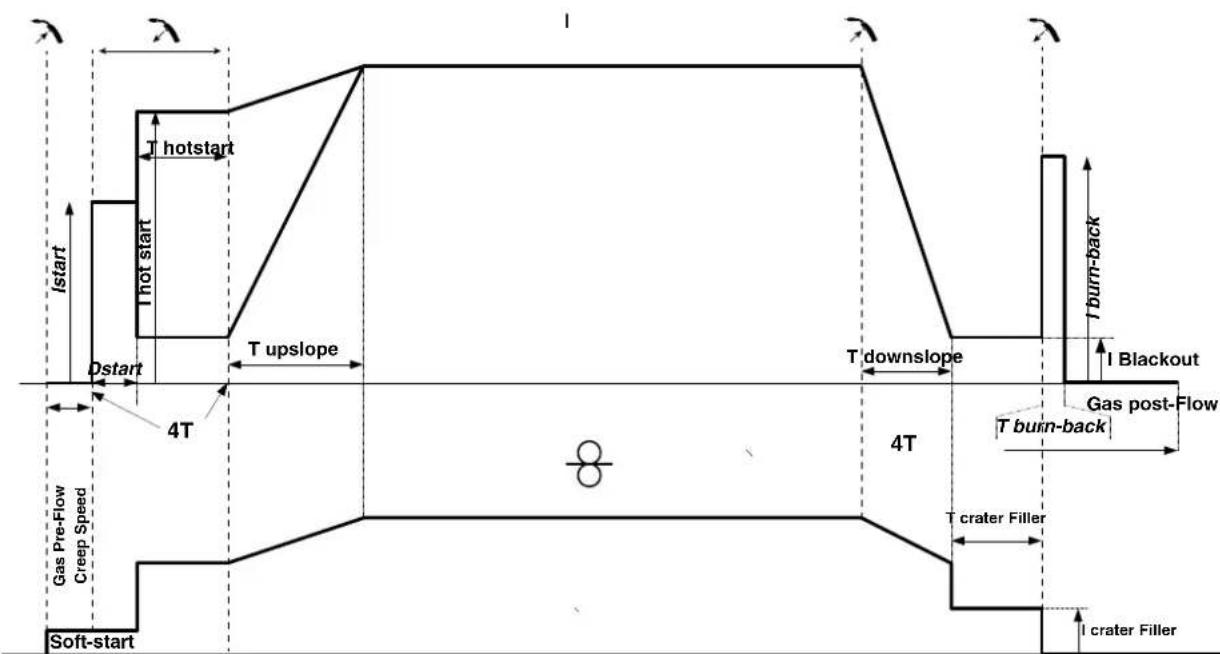
Pulsed 4T process:
In pulsed 4T mode, the timing of the pre-gas and post-gas is managed automatically. HotStart and crater fill are controlled by the trigger.
TIG (GTAW) WELDING MODE
INSTALLATION AND GUIDANCE
DC TIG welding requires a protective gas shield (Argon).
- Connect the earth clamp to the positive (+) plug connector. Plug in the TIG torch (ref. 046108) into the power source's EURO connector and the
reverse cable into the negative (-) connector.
- Ensure that the torch is properly fitted and that the consumables (vice grip pliers, collet bodies, diffusers and nozzles) are not worn out.
The choice of electrode will depend on the current of the DC TIG process.
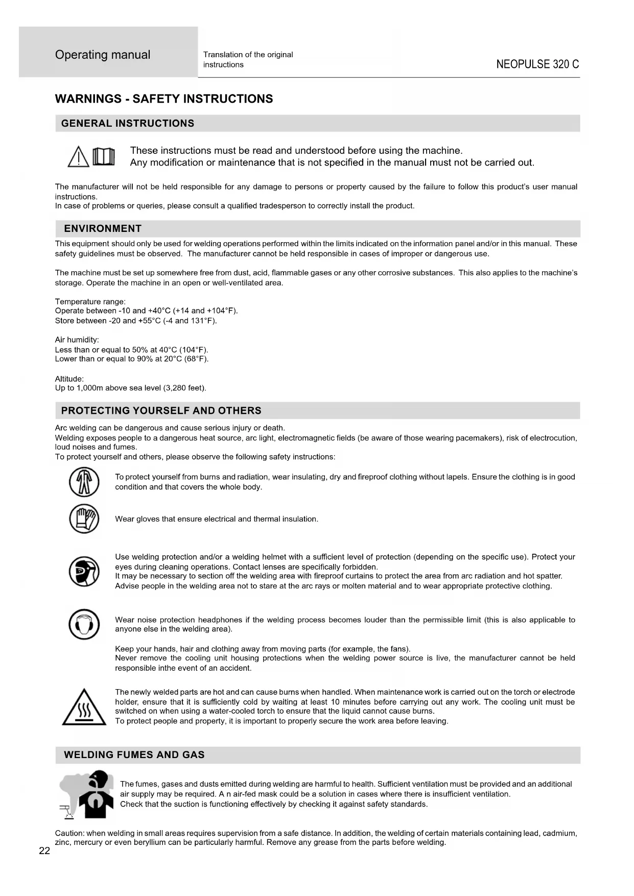
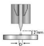
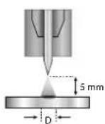
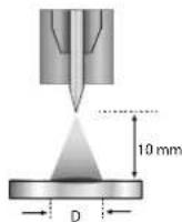
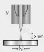
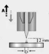
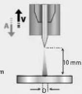
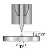
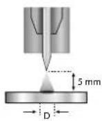
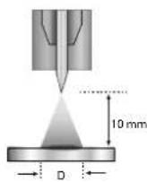
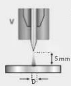
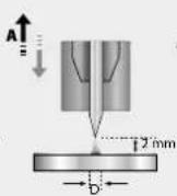
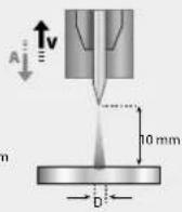
ELECTRODE SHARPENING
For optimum results, it is advised to use an electrode sharpened in the following way:
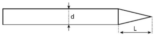
L = 3× d for a low current. L = d for a high current
ASSISTANCE FOR SETTING UP AND SELECTING CONSUMABLES
| DC | ↓↑ | Current (A) Electrode (mm) Shroud (mm) Argo n flow rate (L/min) | ||
| 0.3 - 3 mm 5 - 75 1 | 6.5 6 - 7 | |||
| 2.4 - 6 mm 60 - 150 | 1.6 8 6 - 7 | |||
| 4 - 8 mm 100 - 200 | 2 9.5 7 - 8 | |||
| 6.8 - 8.8 mm | 170 - 250 | 2.4 | 11 8 - 9 | |
| 9 - 12 mm | 225 - 300 3.2 12.5 | 9 - 10 | ||
PROCESS SETTINGS
| Welding processes | ||||
| Settings | ADJUSTABLE SETTINGS | Synergies(pre-installeduser settings) | DC | |
| - | Standard | - | ✓ | Smooth current |
| Pulsed | - | ✓ | Pulsed current | |
| Spot welding | - | ✓ | Smooth tacking | |
| Tack | - | ✓ | Pulsed tacking | |
| Type of materials | Fe, Al, etc. | ✓ | - | Choice of the material to be welded |
| Tungsten elec-trode's diameter | 1 - 4 mm | ✓ | ✓ | Choice of electrode diameter. Allows the refinement of HF firingcurrents and pre-installed user settings (synergies). |
| Trigger mode | 2T - 4T - 4T LOG | ✓ | ✓ | Choice of trigger welding management mode. |
| E.TIG | ON - OFF | ✓ | ✓ | Constant energy welding mode with arc length correction. |
| Power | HoldThermal coefficient | - | ✓ | See «Power» section on the following pages. |
Access to some welding settings depends on the selected display mode: Settings/Display mode: Easy, Expert, Advanced.
WELDING PROCESSES
DC TIG welding
Specifically designed for ferrous metals such as steel, stainless steel, copper and its alloys, as well as titanium.
- Synergic TIG welding
No longer based on the selection of a DC current type and the welding cycle settings but integrates welding rules/pre-installed settings based on real welding experiences. Therefore, this mode restricts the number of basic, adjustable settings to three: Type of material, welding thickness and welding position.
ADJUSTABLE SETTINGS
STANDARD WELDING
The standard DC TIG welding process allows high quality welding on most ferrous materials such as steel and stainless steel, but also copper and its alloys including titanium. The various current and gas management possibilities allow you to perfectly control your welding operation, from priming to the final cooling of your weld seam.
PULSED WELDING
This pulsed current welding mode combines high current pulses (I = welding pulses) with low current pulses (cold I, workpiece cooling pulses). The pulsed mode allows parts to be assembled while limiting temperature rises and warping. Ideal for on site use.
Example:
The welding current (l) is set to 100 A and % (cold l) = 50%, i.e. cold current = 50% x 100 A = 50.
F(Hz) is set to 10Hz , the signal period will be 1 / 10Hz = 100ms a100A pulse every 100ms then followed by another at 50A .
- SPOT WELDING
This welding mode allows the pre-assembly of parts before welding. Spot welding can be done manually using the trigger or timed with a predefined spot welding period. Spot welding allows for better reproduction and non-oxidised weld points.
TACK WELDING
This welding mode also allows for the pre-assembly of parts before welding, but in two stages this time: the first stage uses a pulsed DC current which concentrates the arc for better penetration. This is then followed by the second stage where a standard DC current is used to widen the arc and therefore the weld pool to secure the weld point.
The variable times of the two welding stages allow for better reproduction and non-oxidised weld points.
E-TIG WELDING
This mode allows for constant power welding by measuring arc length variations in real time to ensure consistent bead width and penetration. In cases where the assembly requires careful control of the welding energy, the E-TIG mode guarantees that the welder will respect the welding power regardless of the torch's position in relation to the workpiece.
Standard (constant current)
E-TIG (constant power)
CHOOSING THE ELECTRODE'S DIAMETER
| Electrode Ø (mm) | TIG DC | |
| Pure tungsten Tungsten with oxides | ||
| 1 10 > 75 10 > 75 | ||
| 1.6 60 > 150 60 > 150 | ||
| 2 75 > 180 100 > 200 | ||
| 2.5 130 > 230 170 > 250 | ||
| 3.2 160 > 310 225 > 330 | ||
| 4 275 > 450 350 > 480 | ||
| Approx. = 80 A per mm Ø | ||
USING THE TRIGGER
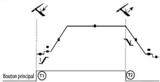
-2T
T1 - The main button is pressed, the welding cycle starts (Pre-Gas, I_Start, upslope and welding).
T2 - The main button is released, the welding cycle is stopped (downslope, I Stop, Post-Gas).
For two-button torches in T2 only, the secondary button is treated as the main button.
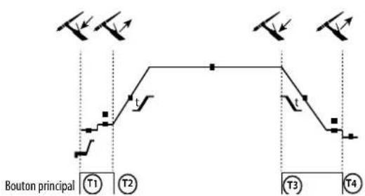
·4T
T1 - The main button is pressed, the cycle starts from Pre-Gas and stops at the I_Start phase.
T2 - The main button is released, the cycle continues to upslope and welding.
T3 - The main button is pressed, the cycle goes to downslope and stops in the I_Stop phase.
T4 - The main button is released, the cycle ends with the Post-Gas. NB: for torches, double buttons and double button + potentiometer => «up/weld current» button turns on the potentiometer, the «down» button turns it off.
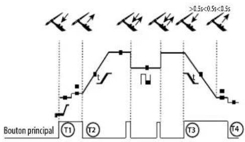
- 4T LOG
T1 - The main button is pressed, the cycle starts from Pre-Gas and stops at the I_Start phase.
T2 - The main button is released, the cycle continues to upslope and welding.
LOG: this operating mode is used during the welding phase:
- a quick press of the main button (<0.5 s) switches the current from I_welding to I_cold and vice versa.
- if the secondary button is pressed, the current switches from I_welding to I_cold.
- if the secondary button is left unpressed, the current switches from I_cold to I_welding.
T3 - After holding down the main button (>0.5 s), the cycle goes into downslope and stops at the I_Stop phase.
T4 - The main button is released and the cycle ends with Post-Gas.
For dual button or dual trigger torches, the «high» trigger retains the same functionality as the single trigger torch. The «low» trigger is not active.
MANUAL GAS FLUSHING
The presence of oxygen in the torch can lead to a decrease in mechanical quality and can result in less corrosion resistance. To flush the gas from the torch, press and hold the button #1 and follow the on-screen procedure.
CONFIGURING THE SETTINGS
Units
| Pre-Gas s When the torch is bled and the gas shield is created before ignition. | |
| Start-up time | % This start-up bearing current is a warm-up phase before the current is raised. |
| Starting time | s Starting time before the current is raised. |
| Rising current s Allows a gradual increase in welding current. | |
| Welding current A Welding current. | |
| Crater-fill feature | s Avoids cratering at the end of welding and the risk of cracking, particularly in light alloys. |
| End current % This idling bearing current is a phase after the current is lowered. | |
| Stopping time s This idling time is a phase that comes after the current is lowered. | |
| Thickness | mm Thickness of the workpiece to be welded. |
| Position | - Welding positioning |
| Post-Gas | s Duration of the gas protection after the arc is extinguished. It protects the workpiece and the electrode from oxidation during cooling. |
| Wave shape | - Pulsed waveform. |
| Cold current | % Second welding current known as a «cold» welding current. |
| Cold weather % Pulsed hot current (I) time balance | |
| Pulse frequency | Hz Pulse frequency SET-UP TIPS: - If welding with a manual, filler metal, then F(Hz) is synchronised to the inputting of the wire. - If the metal is thin and without filler (< 0.8 mm), F(Hz) > 10 Hz - If welding in position, then F(Hz) < 100 Hz |
| Spot welding | s Either manual or a set time. |
| Timed pulsed | s Manual or timed pulsed hase |
| Timed non-pulsed | s Manual or timed smooth current phase |
Access to certain welding settings depends on the welding process (Standard, Pulsed, etc.) and the selected display mode (Easy, Expert or Advanced).
MMA (SMAW) WELDING MODE
INSTALLATION AND GUIDANCE
- Plug the cables, electrode holder and earth clamp into the plug connections.
- Respect the electrical polarities and the strength of the welding power indicated on the electrode boxes.
- Remove the coated electrode from the electrode holder when the welding power source is not in use.
-
The equipment is fitted with 3 inverter-specific features:
-
Hot Start provides an overcurrent at the beginning of the welding process.
- Arc Force creates an overcurrent which prevents the electrode from sticking to the weld pool.
- The Anti-Stick technology makes it easier to unstick the electrode from the metal.
PROCESS SETTINGS
| Welding processes | ||||
| Settings | ADJUSTABLE SETTINGS | Standard Pulsed | ||
| Electrode type | RutileBasicCellulosic | ✓ | ✓ | The type of electrode determines the settings in order to optimise its weldability depending on the type of electrode used. |
| Anti-Sticking OFF - ON | ✓ | ✓ | The anti-stick feature is recommended to safely remove the electrode in the event of it sticking to the workpiece (the current is cut off automat- cally). | |
| Power | HoldThermal coefficient | ✓ | ✓ | See «Power» section on the following pages. |
Access to some welding settings depends on the selected display mode: Settings/Display mode: Easy, Expert, Advanced. Refer to the HMI manual.
WELDING PROCESSES
STANDARD WELDING
This standard MMA welding mode is suitable for most welding applications. It enables welding with all types of coated, rutile, basic and cellulosic electrodes, as well as on all materials: steel, stainless steel and cast iron.
PULSED WELDING
The pulsed MMA welding mode is suitable for upright (PF) applications. The pulsed setting keeps the weld pool cold while promoting material transfer. Without pulsing, vertical upward welding requires a «Christmas tree» movement, i.e. a difficult triangular movement. Thanks to Pulsed MMA welding, it is no longer necessary to perform this movement. Depending on the thickness of your workpiece, a straight upward movement should suffice. However, if you want to enlarge your weld pool, a simple sideways movement similar to downheld welding is sufficient.. In this case, you can set the frequency of your pulsed current on the display monitor. This method offers greater control of the vertical welding operation.
CHOOSING COATED ELECTRODES
- Rutile electrodes: very easy to use in any position.
- Basic electrodes: it can be used in all positions and is suitable for safety work due to its increased mechanical properties.
Cellulosic electrodes: a very powerful arc with a high melting speed, its ability to be used in all positions makes it especially suitable for pipeline work.
CONFIGURING THE SETTINGS
| Units | ||
| Percentage Hot Start | % | Hot Start is an overcurrent at the ignition stage which prevents the electrode from sticking to the workpiece. The intensity (% of welding current) and the time (seconds) can be programmed. |
| Duration of Hot Start s | ||
| Welding current | A | The welding current is determined by the type of electrode chosen (see electrode packaging). |
| Arc Force % | Arc Force is an overcurrent administered to prevent sticking when the electrode or weld bead touches the weld pool. | |
| Percentage I cold % | ||
| Cold weather s | ||
| Pulse frequency | Hz PULSE mode's PULSING frequency. | |
Access to some welding settings depends on the selected display mode: Settings/Display mode: Easy, Expert, Advanced. Refer to the HMI manual.
ADJUSTING THE WELDING CURRENT
The following settings correspond to the applicable current range depending on the type and diameter of the electrode used. These ranges are quite large as they depend on the usage and the welding position.
| electrode Ø (mm) | Rutile E6013 (A) | Basic E7018 (A) | Cellulosic E6010 (A) |
| 1.6 | 30-60 | 30-55 | - |
| 2.0 | 50-70 | 50-80 | - |
| 2.5 | 60-100 | 80-110 | 60-75 |
| 3.15 | 80-150 | 90-140 | 85-90 |
| 4.0 | 100-200 | 125-210 | 120-160 |
| 5 | 150-290 | 200-260 | 110-170 |
| 6.3 | 200-385 | 220-340 | - |
ADJUSTING THE ARC FORCE
It is advisable to set the Arc Force to the middle position (0) to start welding and then adjust it according to the results obtained and individual welding preferences. Note: The adjustment range of the Arc Force is specific to the type of electrode chosen.
POWER
A method developed for welding with DMOS-regulated energy control. As well as displaying the energy of the weld bead after welding, this mode allows the setting of the thermal coefficient according to the standard used: One for ASME standards and 0.6 (TIG) or 0.8 (MMA/MIG-MAG) for European standards. The energy displayed is calculated taking into account this coefficient.
OPTIONAL PUSH-PULL TORCH
| Reference number | Wire diameter Length | Cooling type | |
| 038738 0.8 > | 1.2 mm 8 m Air | ||
| 038141 0.8 > | 1.2 mm 8 m Liquid | ||
| 038745 0.8 > | 1.6 mm 8 m Liquid |
A push-pull torch can be connected to the power source via the socket (I-11). This type of torch allows the use of AlSi wire even in 0.8mm with a torch length of 8m . This torch can be used in all MIG-MAG welding modes.
The Push-Pull torch is detected by simply pulling the trigger.
When using a push-pull torch with potentiometer, the highest control range setting can be set using the interface.
The potentiometer can then range anywhere between 50% and 100% within this setting.
OPTIONAL REMOTE CONTROL
- RC-HA2 Analogue remote control (ref. 047679):
An analogue remote control can be connected to the power source via the socket (I-11).
This controller acts on the voltage (first potentiometer) and the wire speed (second potentiometer). These settings are then inaccessible from the power source's interface.
- RC-HD2 Digital remote control (ref. 062122):
A digital remote control can be connected to the power source via the NUM-1 Kit (option ref. 063938).
This remote control is designed for MIG/MAG, MMA and TIG welding processes. It enables the welding unit to be controlled remotely. An ON/OFF button is used to switch the digital remote control on or off. When the digital remote control is switched on, the HMI power source displays the current and voltage values. As soon as the HMI is switched off or disconnected, the HMI power source is reactivated.
OPTIONAL COOLING UNIT
| Reference | Designation | Cooling power | Tank capacity | Power supply voltage |
| 013537 WCU 1KW C 1000 W 5.5 L 400 V +/-15% | ||||
The cooling unit is automatically detected by the machine. To deactivate the cooling unit (OFF), please refer to the interface manual.
The protections supported by the cooling unit to ensure the protection of the torch and the user are:
- Minimum coolant level.
- Minimum flow rate of coolant flowing through the torch.
Thermal protection of the coolant.
Make sure that the cooling unit is turned off before disconnecting the inlet and outlet hoses for torch liquid.
The coolant is harmful and irritates the eyes, the mucous membranes and the skin. Hot liquid may cause burns.
DRIVE ROLLERS (F) OPTIONAL
| Diameter | Part Number (x4) | |
| Steel | Aluminium | |
| Ø 0.6/0.8 | 061859 | - |
| Ø 0.8/1.0 | 061866 | 061897 |
| Ø 1.0/1.2 | 061873 | 061903 |
| Diameter | Part Number (x4) |
| Flux-cored wire | |
| Ø 0.9/1.1 | 061927 |
| Ø 1.2/1.6 | 061934 |
| Ø 1.4/2.0 | 061941 |
If the drive rollers are found to be worn or if using a filler wire with a diameter >1.6mm it is advisable to replace the plastic wire guide:
| Diameter | Colour | Part Number |
| Ø 0.6>1.6 | blue | 061965 |
| Ø 1.8>2.8 | red | 061972 |
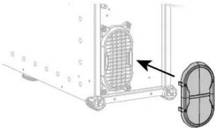
OPTIONAL FILTER KIT
Dust filter (PN. 063143) with a filter fineness of 270 m (0.27 mm).
Please note that the use of this filter reduces the duty cycle of your machine's power source.
To avoid the risk of overheating due to blocked air vents, the dust filter should be regularly cleaned.
Unclip and clean with compressed air.
ADDITIONAL FEATURES
The manufacturer GYS offers a wide range of features that are compatible with your product. To check them out, scan this QR code.

DEFECTS: CAUSES & SOLUTIONS
| SYMPTOMS POSSIBLE CAUSES SOLUTIONS | ||
| The flow of the welding wire is not constant. | Clogs blocking the opening. | Clean the contact tube or replace it with non-stick material. |
| The wire slips in the roller. Reapply the non-stick product. | ||
| One of the rollers is spinning. Check the tightness of the roller screw. | ||
| The torch cable is twisted. | The torch cable should be as straight as possible. | |
| The reel motor is not working. Reel brake or roller is too tight. Loosen the brake and rollers. | ||
| Incorrect wire unwinding. | Dirty or damaged wire guide. Clean or replace. | |
| Roller pin key is missing. Reposition the pin in its slot. | ||
| Reel brake is too tight. Loosen the brake. | ||
| No current or wrong welding current. | Improper connection of mains plug. | Check the plug connection and verify that the plug is connected to the power supply. |
| Poor earth connection. | Check the earthing cable (its connection and the condition of the clamp). | |
| No power. Check the torch trigger. | ||
| The wire jams after passing through the rollers. | Crushed wire guide sheath. Check the sheath and torch. | |
| Wire jamming in the torch. Replace or clean. | ||
| No capillary tube. Check that the capillary tube is present. | ||
| Wire speed too high. Reduce the wire speed. | ||
| The weld bead is porous. | The gas flow is insufficient. | Adjustment range from 15 to 20 L / min. Clean the base metal. |
| Gas cylinder empty. Replace it. | ||
| Unsatisfactory gas quality. Replace it. | ||
| Air circulation or wind influence. | Avoid draughts and protect the welding area. | |
| Gas nozzle is too clogged. | Clean or replace gas nozzle. | |
| Bad wire quality. | Use a wire suitable for MIG/MAG welding. | |
| Condition of the welding surface is too poor (rusted, etc.). | Clean the workpiece before welding. | |
| The gas is not connected. | Check that the gas is connected to the power source's inlet. | |
| Excessive sparks. | Arc voltage is too low or too high. | See welding settings. |
| Poor earth connection. | Check and position the earth clamp as close as possible to the area to be welded. | |
| Insufficient gas protection. Adjust the gas flow. | ||
| No gas coming from the torch. Poor gas connection. | Check the connections of gas inlets. | |
| Check that the solenoid valve is working. | ||
| Error while downloading. | The data on the USB stick is incorrect or corrupted. | Check your data. |
| Backup error. | You have exceeded the maximum number of backups. | You need to delete some programs. The number of backups is limited to 500. |
| Automatic deletion of JOBS. | Some of your JOBs have been deleted because they were incompatible with the new pre-installed user settings (synergies). | - |
| Push Pull torch detection error. - Check Push Pull torch connection. | ||
| USB key error. | There is no JOB detected on the USB stick. - | |
| The product's memory space is full. Free up some space on the USB key. | ||
| File error. | The file does not match the pre-installed user settings (synergies) downloaded to the product. | The file was created with pre-installed user settings (synergies) that are not present on the machine. |
WARRANTY CONDITIONS
The warranty covers any defects or manufacturing faults for two years from the date of purchase (parts and labour).
The warranty does not cover:
- Any other damage caused by transportation.
- General wear of parts (eg.: cables, clamps, etc.).
- Damage caused by misuse (incorrect power supply, the dropping or dismantling of equipment).
- Environmental failures (pollution, rust and dust).
In the event of a breakdown, return the appliance to your distributor, together with:
- dated proof of purchase (receipt, invoice, etc.),
- a note explaining the breakdown.
HnB KOem cnyyae He Bapntb B6nn3n Jkpa nJn Kpackn.
PICK IOXAPA N B3PbIBA

NoHocTbO 3aunntte 30Hy CBapKn. Bo3ropaembl MaTePnAbl DoNkHb6bTy ydaenHb KaK MNHMym Ha 11 MetpoB. PpnoBnOIOXapHoe o6opynOBaHne DoNkHO HaxoDnTBcB6n3n npoBeeHn CBapOHyx pa60T.
OcToPoxHo C 6pbI3ramrnpaero MaTePnana nNn Nckp. OHI MOrY T nobNey 3a c06oN noKap nNn B3pbIB daxe chepe3 uen.
YdaIte IIOe, Bo3ropaemble npeMeTb N BCE emKocn noD daBHeHem Ha 6e3onacHoe pacctOraHne.
Hn B KOem cnyae He Bapnte B KOHTeHepax nnn 3akpbTbIX Tpy6ax. B cnyae, ecln OHn OTkpbl, To nepeC CBAPKOn Hx HyXHO OCBOOHTb OT BCEx B3pbBcTaBix nnn BO3ropaembIX BeueCTB (MacNo, TonNIO, OCTaTOHHe ra3bl ...).
Bo Bpem Oepaunu HnfoBAnH He HapBaTne HNCTpyMeNT B CTOpOHy NcToHHKa CBAPOHOro ToKa IIN BO3rpaEmbIX MaTePnaNoB.
T30BbIEBAJIIOHbI

Tg30M, BbIXoJHIM N3 ra3ObBix 6aIIOHOB, MoKHO 3aDOxHybC B Cnyae erO KOHcHTpaCIN B NOMeEHN CBAPKN (XopoIo npOBeTrpuaBaiTe).
TpaHcnopTpOpBka DoJNkHa 6bTB BbINOnHeHa 6e3oNaCHO: UININHpB3aKpbItb, a NCTOCHK CBAPOHOr TOKa BbIKIOueH. BaIIOHO bdoJHKb6bTB BepTKaJIbHOM NOJOKEHNI 3aKpenPHeHb HA NOCTaBKe, YTObI OPAHNHTb Pnck naDeHnA.
3aKpbBaIte 6aIIIOH B nepepbIbe MeJy DByMg IcNoIb3OBAHnM. ByIbTe BHNMaTeJIbHbI K N3MeHeHIO TeMnePaTybpI NpE6bIbaHIO HA cONHc. BaIIIOH He dOnXeH cOpNkacatbcra C PnameHem, 3JeKtpuYecko dyro, rOpEnKO, 3aXIMOM Maccbl nC lIObIM npYHM nCTOUYKOM Tepna nn CBeueHn.
Eepxnte ernoaIbwe ot 3neKtpnuecknx n CBapOHybIX cenei, CneObaTeNbHO, HNKorTa He BapTe 6aannoh noD daBneHHeM.
Bbte BnHMaTeIbHbI: npOtKpbTIN BeHTnla 6aIIHOHa y6epnte roNoby o Hrero n y6eNTecb, qTo IcNtB3yEmbl r3 COOTBeTCTByET MeToYo CBapKn.
3JIeKTPnueCKAeB3OAnACHOCTb

IcnoB3ayemar 3JIeKTPnueckara cetb DoJxHa o6a3aTeNbHO 6bITb 3a3EmneHHo. Co6nIOaIte KaIN6p npedoxpaHHTeYkzaAHhHa annapate.
3NeKtpueckn pa3pnd MOKeT Bbl3BaTb npMbIe NIN KOCBeHHbIe paHeHry, n DaXe CMeptb.
HkoIa He doTpaBaiTeb Do uacte IIOd HapRaeHHeM KaK BHyTpN, TaK n ChapyKn NCTOuyHnka, KOrda OH NOd HapPaeHnEM (ropeKN, 3axMbI, ka6en, 3neKTpobl), T.K. OHN IOkNIOUeHbIK CbapOuHn ceni.
Pepedem, KaK OTkpblb NCTOCHNK, eHO HyxH0 OTKnIOHTb OT cETN IIOOKDaTb 2 MInHyTb IINr TORO, YTO6bl BCE KOHNDeHCaTOPb pa3prnncb.
HkoHa He DoTpaNbAaTeBcOHOBpeMeHHo Do ropeKn Hnn 3JeKtpoOepKaTeJn I Do 3axMa MaccbI.
Ecn KabeHn, ropEnK nOBpeJeHbI, nonpocnte KbaInuNpuOpBaHHbIX u ynoHMOHeHHbx CneuaJNCTOB x 3aMeHtB. Pa3Mepbl ceehnna Ka6enei dOxHbCoOTBeTcBOBaTb npimeHenIO. Bcerda HocTe cyxyo OdekBy BXopoWem COCToHIN DnI N3OnraU ON CBapOHOu HcHte I30npyioyoo6yBb He3aBncMoO TO ToI cpeBIs, rde Bbl pa6oTaTe.
KJIACCNUKAUJN 3JEKTPOMAHHTHON COBMECTMOCTN

3TO 60pOyOBAHnKlACCA A He NoDxOoNT DnI NcNoBtOBAHnB B KInbIX KBaPTanax, rIe 3NeKTPuyeckn TOK noDAETCBOUCTBEHNO CNTEmoN HNTAHN Hn3KORHO HApRKeHnB. B TaNX KBaPTanax MOrY Bo3HNKHyTb TpyHOCTn ObecneueHn3NEKTPOMaHTHNYO COBMeCTMOCb I3-3a KOHdyKTNBbIx INHdyKTNBbIx NOMex Ha paAnOacToTe.
3ToT annapaT COOTBeTCTByeT HopMe CEI 61000-3-11.
3TOT annapat He cooBcTByet DnpeKtBcEi 61000-3-12 n npedHa3NaeHnPa60bI OT qacthbx 3NeKtpocTe, NOBedeHHbIX K O6ueCTBeHHbIM 3JIeKTPocETM TOJbKO cpeHero N BbICOKO HAnpJxHeH. CneuaNInCT, yCTaHOBVHnn annapat, INI NIOB3OBAteB, DOJKNbI y6eDITbcR, O6paTHBUnCb Pn HAdo6HoCTN K OprAHn3aun, OTBeYauSeH 3a 3KcPnyatauio CNTEmbl NTaHnB, B TOM, YTO OH MOKeT K HeI NOkKnOHHTbcR.
MAGHHTbIe NIOJIa
3NeKtpnueckn TOK, npoxoJauu chpe3 IIO60 npOoHb Kbl3bBaet NkAn3OBaHHbe 3NeKtpomarHHTbIe nON (EMF). CbaOpHbTOK Bbl3bBAET 3NeKtpomarHHTHOE NOE BOKpyc CBapOHOU cENN CBAPOHOrO o6opyOBAHNA.
Bce cbapuikn doJHKbI nCIOJIb3OBaTb CneDyUOme npoceDpybl Ira MNHMM3aUN BO3JeCTBNA 3JEKTPOMaHTHBIX NOeN:
pacnoIOXnTe CBapOuHbIe KaBEn BMeCTe - NO BO3MOxHOCTn 3aKpeNITe INC NOMOULIO 3aKIMMa;
-ДерхиТecь кak MoxHо Дальшо OТ CBAPOчноцп
Hn B koem cnyahe He obopauuBaIte BOKpyr ce6raBapouhblkeab
- He pa3meaai Te Kopnyc Mekdy CBAPouhBIMKa6eIaMn. Depxte o6a CBAPouhBix Ka6eIa Ha OdHoi CTOpOHe Kopnyca;
- PndcoeHNHe 6bathnK a6eJI K 3aTOrOBKe KaK MoXHO 6NIXe K CBapnBaEMOMy yAcTky;
He paobotaTe pIOM, He caNTecb n He npCNOHnTEcb K nCTOuHky CBapouHoro TOka;
- He CBAPINBaTb npu TpaHCnOpTIpOBKe nCTOChNka CBapOCHOro TOKa INy UcTpOiCTBa IOnaHn PpOBONK.

Iiua, nCnoB3yUoHne 3JektpokapDnocTmMyIaTOpbI, DOnKHbI npOKOHcyNbTpOBAbCBy Bpaaypeepa6Toon C daHHbIM o6opuyoBaHnem.
Bo3eCTBnE 3NektpomarHHTHO NOI B npoceCE CBAPK MoKet IMeTB N dpYrNe, eue He H3BeCTHbIe HayKe, nocneCTBnI
IJI 3IOPOBbI.
PEKOMEHNDAUINIJI OUEHKN 3OHbICBAPKN I CBAPOHON YCTAHOBKN
06uue CBeHn
Ponb3oBATENB OTBeaet 3a yctahOBky n cncOJIb3oBaHne yCTAHOBKn pyuHNO dyROBO CBAPKn, cIeDyra yka3aHNMA npOn3BOITEN. PnO6hApUKeHHN 3JekTPOMaHTNbX INyUeyHn NOIb3oBATNB annapata pyuHO DYROBO CBAPKn DOxKHe paoNEMy C NMOUcBTO TexNHueCKO NOdEeKNN pON3BOITEN.B HEKOToPbIX CNyAax 3TO KOPpeKTpyHOue DeCTBne MOKET 6bTb DOCTaTOH NOpCtBM, HAnpIMep 3a3eMNEHne CBAPOHO JcENB Dpynx CNyAax BO3MOxHO nOTpe6yeTCs CO3DAHNe 3JekTPOMaHTNTHoro 3kpaHa BOKpy IcTOHnKa CBAPOHOR TOKA n BCen CBAPBaEMOJ DEtanN PyTeM MoNTPOBAHn BXODNbX fINbTPOB.B NIObOM CNyae 3JekTPOMaHTNTHbe INyUeyHn DOxKHe b6bTb YMeHBSeHb TAK, YTObObl OHI BoNBwe He CO3DaBaHn NOMEX.
OueHka CBapoHoi 30HbI
Ipeed yctahOBKoOobopyoBAnHny dyroBoi CBAPKn Nolb30BaTeJI DoJIkeH OueHHT Bo3MOXHbIe 3NeKTpOMaHHTHbIe np6JIeMbI, KOToPbIE MOryt B03HNKHyT B OkpykaHOSe cpeJe. YTO donxHo 6b1b yUTeHo:
(a) HAIHnue HAD, PND IN PRAOM C OOBpyoBDAHmE DnA yROBOI CBAPKINpYHX CNIOBbIX, YnpaBnHOUX, CNHnBbIX n TenefoHHbIX Ka6eNei; 6)PnemHnIKN INpePaTCHNK paINO IN TEENBDEHNI.
(B)KOMNbIOTepeHINpyrOe KOHTpoJIbHOe O6OpyIDoBaHHe;
r) obopydOBaHne, imEoOe pewaoOee 3NaueHne dIg 6e3onachocTn, Hanpimep 3aunita npombuHHO oobopydOBAHN;
I) 3doopBbe IIOeien, KOtOpbIe HaxoJrTcra No6nI3OCTH Hapmep, pni NcNoJIb3ObaHIn KApDIOOCIMyIaTOPOB INN CnyXOBbIX annapaTOB;
(e)obopydoBaHne,ncnoB3ayEmoeIraKaNb6pOBKnIINn3MepeHnra;
()HEBOCnpnMMHBOcTbDpyrOoobopydOBaHnKOKpyKaUoJe CpeJe.
Ib0BteBdoJxH y6eHTbcB TOM, YTO Bce aannapabB NOMEeHN COBMeCTMbl Dpyr C Dpyrom. 3To MoKET noTpe6oBaTB DononHInTeBHBIX 3aunTHbIX Mep;
(Ⅲ)BpeMcyTOK, KOrdaDOnJXHbI npoBoDnTbcra CBapOHyIe IIN dpyrme pa60TbI.
Pa3mepb paaccMatpmbaem030hblcBapkn 3abncrt OT ctpktypbl 3daHnN n pyrnx pa6oT, KOtOpble B hem npobOanr. Paccmatpmbaemar 30Ha MoKeT npocntpaTbcra 3a npedeJIbI pa3MeueHnYcTaHOBKn.
OueHka cbapouhoN yctaHOBKn
POMMIMO OueHKI 30HbI, OueHKa aannapatoB pyHOn dyroBOB CBAPKMOKet NmOy bOppeNtB npeuHT cbnyan 3neKtpomarHnTHbIX NOMEX. OueHKa H3nyeHHIOJOKHa yUHTbIBaTB N3MepeHHBA yCNOBHX 3KcNpyaTauHN KAK 3TO yKa3aHO B CtaTbe 10 CISPR 11:2009. N3mepeHHBA yCNOBHX 3KcNpyaTauHN MOrY TAKKe I03BOINbI NOITBePdNTB 3ΦΦeKTHBHOCTb ME pNo CMrYeHHIO BO3DeNCTBNA.
PEKOMEHDAUINI NO METOANDKE CHNXEHNIALEKTPOMAHHTHOI3JnyEHNIA
a.ObseCTBeHHaCetb cha6KeHn: ObopyoBaHHe dny DyrBOB CBAPKn DoJNHO 6bItb NODKIOUeHO K O6IeCTBeHHOMy 3NeKTPocHa6KeHnIO B COOTBETCBn CpeKomeHdaIaIMy npoI3BOIteJI.B CNYae BO3HKHOBEHn NOMEX BO3MOXHO 6yET Heo6xOdIMo pInHrTb DOOnJIHTeJIbHbe IpeDynpeIITbHbIe MePbl, TAKNE KAK FInbTpauia O6IeCTBeHHOI CICTeMbl NITAHIA. Bo3MOxHO 3aUHTb 1hyp PNTAHNA annapaTa C NOMOIO bEPAHn3uPyIOSe ONIeTKn, INo5o NOxOXM INcncO6bEnHem (B Cnyae eCN AnnpaT pyHoi DYROB CBAPKn NocToHNO HaxOINTC Ha ONpeDeEHNM paOboMeTc). Heo6xOIMO o6ecneHtB 3NkTpueeckyo HenpepbIBHOCTb EkaHn3uPyIOSe ONIeTKn IO BcEN DnHE. Heo6xOIMO NOCoEOHNb EkaHm3uPyIOUyIO ONIeTKy K NcTOOHNK CBAPoHOro TOKa dner o6ecneHn XopoWero 3NeKTPuueckoro KOHTaMeKdy MHexy MHypom I Kopnycom hctOCHNkcaBapouHOro TOKA.
6. Texnueckoe 0cbnyxnbHne 0bOpDobAHnI dnyroBo CBAPK: O6opyoBaHne IydyroBo CBAPK DoXHO pOxOHTb peYrnapHoe Texnueckoe 0cbnyxnbHne B COOTBETCTBN CpeKOMHeJaunm npO3BOJnteN. Heo6xoJIMO, YTO6bI BCE DOCTynI, IIOK IN OTKnDbBAUHceC AChT KOpNyCa 6bln 3akpblt b npaBnIbHO 3akpenIeHb, KOfA annpaT pyHOn DYROB CBAPK rOToB K pa6Ote NIN HaxoITcB P a6Oyem COCTOHN. Heo6xoJMo, YTO6bI annapat pyHOn DYROB CBAPK He 6bln nepeEanah KaKIM 6bl TO HN 6blIO opa3OM, 3a NCKIOuOHeHem HAcTPOE, yka3AHbX B pyKOBOdTeB npON3BOJNTeN. B UACTHOCTN, cJeTyEOT pOryIpOBaT b NOClyXBnBaT NCKPOB nPOMexyTok dyrN yctPoCTB NOkMra n CTaBnI3aUN DyrN B COOTBECTBN CpeKOMHeJaunm npON3BOJNTeJIA.
B.CBAPOUHbIE KABEN CuIOBbIe Ka6en : Ka6en DoJIKbI 6bITb KaK MoXHO KopoYe n NOMEuHbI dpyr prdom C dpyrom B6n3n OT nona nnHa nony.
r. 3KBNIOTeHcuaJIbHOe coeHNHeHne: 3KBNIOTeHcuaJIbHbIe coeHNHeHne: Heo6xoJIMO oecneHTb coeHNHeHne BceX MeTaIIuHECKNX npdMeTOB OKpykaIOSeI 30HbI. TeM He MeHee, MToaJIINueCKNe ppeMetbI, coeHNHeHbIe Co CBapnBaEMoI dTeAIBIO, yBeJIyUHBAOT PnCK I nONb3OBaTeIg Ydapa 3NEKTPuueckm TOkOM, ecNI OH OJHOBpeMeHHo KcHETcra 3TNX MeTaIIINueCKNX npdMeTOB n 3JeKTPoJa. OepaTop DoJxKeH 6blTb N3OpnoBaH OT TAKIX MToaJIINueCKNX npdMeTOB.
3a3emnne 3arotbKn: 3a3emnne Cbapnaem DetanB Cnyae, ecn Cbapnaemag DeTaN He 3a3emnne H No coo6paKeHnM 3eKtpnueck0 beoanaCtoN B CNYBcNOxP a3MePOB N CBOero pacnoioxeHn, Ka, HApnpMeP, BCyae KOpNyCa CyHaN MeTaNNOHOCTpyknn nPomblneHHoro Obekta, To coeHNHeHne DetanC 3mNe, MoKET B HEKOTobX CUYaR, HO He CNCTeMaTHeCKN, COKaTtB Bbl6pOcb. Heo6xoDIMO 136BaTeB 3a3emnne Detane, KOTope MoNBI bYBeuHNT DnI NaNo3oBaTeN pNCK paHEN INI Xe NOpeDIn DpyrmeN eKTPoyctAHOBKn. PnHADIObHcNt, cndyert HAPrmy IOdcoeMHntDeTaN K 3eMne, HO B HEKOTobX CTpaHax, KOTope IpePaeeWAnOT pnpmo NDcoeDHeHme, erO HyKHO CdeLaTc NOMOsbIO NOxOJaIeKO HDeHCaTopa, BB6paHHoro B 3aBNCIMocTOn DT HAIOHOJIbHO 3aKOHDoTeJIbCTBA.
e. 3aunTa n 3kpaHnpoBaHne: 3aunTa n 3kpaHn3npyuOuaonlTeKa: BbIbOpouHaer 3aunTa n 3kpaHn3npyuOuaonlTeKa npytnx Ka6enei n obopuyoBaHna, HaxoJauXcB B 6m3JexaUem pa6oem yactke, nomoxet orpaHnHTb np6IeMbl, CBraHHbIe C nomexamN. 3aunTa BceB CBapOHyOH 30HbMoKeT paccMaTpNBaTBcB N HeKoTOpbIX Oco6bIX cnyaX.
TPAHCIOPTNPOBKA IN TPAH3NT NCTOCHNKA CBAPOHORO TOKAK

NcToHnKa CBapOHHo TOka OCHAueh pyKamn DnA TpaHCnopTPOBKn, No3BOJIAUOMM NpeHocntb annapat. ByIbTe BHNMaTeNbHbI: He HeDOOeHnBaTe Bec aannapaTa. PyKoRTKa(-) He MoKeT(-rT) 6bITb NCNoJIb3OBAHa(-bl) dna CTponOBKn.
He nonb3yntecb ka6enm mnn ropekn Dnna nepeHocn cToCHnKa CBapOHHo ToKa. Ero moXHO nepeHocnTb TOnkOB BBePTKanbHom noJoxKeHHN.
He nepeHocntb nToCHNK ToKa HnIIOdbMn IInn PneDMetamn.
HkoTda He noDHMmaTe ra3OBbI 6aIIIOH IN CTOuyHK CBAPoHoro TOKA OHOBpeMeHH. Ix TpaHCnOpTHbe HopMbI pa3NuaHOTcR.
KeNaTeBHO CHrTb 6oBnHy npOBONK npeD TeM, KaK NOHIMaTB NII INI nepeHOCHTb ICTOuHNK CBAPoHORTO TOKa.
YCTAHOBKA ANIAPATA
- NocTaBbTe IcToUHnK CBapOuHOro ToKa Ha NoI, MaKcImaJIbHbIi HAKIOH KOtOporo 10^
- PnpDycmptnto doctatoH0 6oIbwoe npoctpaHCTBO IIN XOPOwero npOBETPBAHn INTOCHNk CBAPOHOr TOKa N DOCTyNa KynpaBneHIO.
He nCnoJb3OBaTb B cpeDe coOpjkaeM metaJIInueckyIO nbIb-NpOBoDNIK. - NCTOCHK CBAPOHORO TOKA DOJXeH 6bTb YKpbIT OT pONINBHO DOJKn He CToRt Ha cOnHc.
- Annapat 06naaet CTeneHbIO 3auNTbl IP23, yTO O3NaayeT:
-3aunTyOT He6oJbux TBepdbix HnOPOdHbIX TeI DnaMeTpOM ≥12.5MM n,
-3aunTy OT kaneB BOdbI, nadaouxN oD yrnom Do 60^
3To 6opdyoBaHne MoKet 5bIb NcNoJIb3ObaHO BHe NOMEeHn COOTBcTBeHHO KNaHTy IP23.

Bnykaohne CBAPOHbte KNOyT pa3pyuHT 3a3emnHOUne npOBOda, NOBpeHt b o6opyoBaHne n 3Jektpueckne np6Opbl N Bb3BaTb HapReBaHne KOMJIeKTKUOxN, YTO MOKeT pINBeCTN K NOkApy.
-Bcecbapoohbie coeHHeHndoJXhI KpEnKO depKaTbC. IpOBepeTe nx perynphO!
- Y6eDnTecb B TOM, YTO KpePnneHne DeTaI npOuHoe n 6e3 3NeKtpnuecknx npo6JIem!
- CoeINHtBe Bmte HIN NIOBecbTe BCE 3nEMeHTbl CBapOCHoro nCToUHnKa, npoBOJrue 3JIeKTPuYeCTBO,TaKne,KaK WACCn, TeJeKsN I NODbemHbIe 3JIeMeHTbl, uTO6bl 3OJInpOBaTb ux!
- He KlaaIte Ha CBapOHy IcToUHk, Ha TeNExKy IIN Ha NoD'EmHbI eIeMeHTbI TaKe Inp6Opbl, KaK dpEn, ToUHbHbI MaunHKn T.D., ecIn OHn He n3OJIropoBaHb!
- Bcerda knaIte cbapOHbIe ropeKn nIIN 3neKtpoDoepKaTeIHa nIIOJIPOBaHHyIO NOBepxHOCTb, KOrDa Bbl nx He nCNoJb3yeTe!
Hyp nntaHa, ydnnHteB nCBapOHyk Ka6eBdoKnHbNoNHOCTbO pa3MoTaHb BO 36exAHne nepepeBa.

Ipn3BODnteH He HecET OTBeTcBEHOCHTN OTHOCNTeJIbHO yuepe6a,HaHeceHHOrO IuIam IIN PpeMetam, n3-3a HenpaBnIbHoro nOnachoro NcNoJIb3OBaHnE 3TOrO o6OpyDobAHn.
OBCLJYKINBAHNE/PEKOMEHDAUIN


- TexHueckoe 06cnyKbAHne DoJXHO npOn3BOuNTbcr TaBko KBaINΦnUPOBaHHbIM CneuaJIncTOM. CobTeYeTc npOBoHTb exeroHoe TexO6cnyKbAHne.
-
OTKIIOHTe NITAHne, BbIdepHyB BNIKy n3 po3eKn, n noIOxKDNTe 2 MNHyTbI nepei TEM, KAK npNCTyINTB K TexO6cnyKINBAHIO. BHyTpI annapaTa BbICOKne I onaChIbe HAnpJKeHne I TOK.
-
Perynpho OtkpbBaIte annapat n npOyBaIte ero, yTo6bI ouHCTMb OT bJIIN. Heo6xOIMMo TAke ne pOBepaBt Bce 3neKtpueckne coeDInHeNc NOMOsbIO hONIpOBaHHOrO INHCTpyMeHTA. IpOBepKa DOJIXHA OcyuEcTBnT BcR KBAJIINΦUINPOBaHHbIM CNEuaNICTOM.
- Perynlo npoBepre CoToHne UHypa NHTAHN.EcHn UHyp nHTAHN NOBpeKDeH, OH DOJKeH 6bIT bAmeHeH pOn3BODnteEM, eO cepBnCHOn clykbo nn KBaAnFmupOBaHHM CneuaanCTOM BO n36exHane ONaCHOt.
- OctabTnE OTBepCTnN hCToOnHnKa CBapOHyOro ToKa CBo6OdHbIM nI npoxOxDHeH N Bo3Dyxa.
- He nCnoJIb3OBAt b DaHHbI annapaT dIpa pa3MOpO3Kn Tpy6, 3apAkn 6aTape/AKKyMyJrToP0B NII 3Anycka DnRaTeJeN.
YCTAHOBKA IN PPNHUN DEIeCTBNA
ToIbKOOnbTHNHyyONHOMOHeHHbIpON3BOIDTeMeCneuaNCTMOKeTcOyueCTBnYcTaHOKBy.BoBpeMycTaHOBNy6eDntecb,TOHcTOHNKOTKnIOHcTcN.PocNeIOBaTeNbHbIEINPapaNNbHbIEcoEInHeHnIcTOHnKaanpeuHb.I.PekomeHdyETcNcNoB3OBaTBcApOHTbeKa6eIMNduyueB KOMNKeTE cannapAton dIra ONtHMaNHOH HAcTPOKNMaunHbI.
ONICAHNE
3To Tpexpa3HbN NCTOCHN NITAHnI DnK CnHepreTnecko] nnyaBtOMaTHeCKo CBapKn (MIG nIN MAG), CBAPKn 3NeKTpoDom c 6Ma3koi (MMA) IN dnnCBAPKn TYrOJIaBKM 3NeKTPOdom (TIG).Dn200-x 6o6uH 0 300 MM.
ONICAHNEOBOPYIOBAHNA (I)
1-NepeKJIuOaTeIb ON/OFF 9- INHTepFeIc CheNoBek/MaunHa (IHM)
2-KonHeKTop dna rasa 10-LuΦpoBoi pa3bEm RC (onua, cblka. 063938)
3-Ka6eHbBn BBOd (ceTeBoN Ka6eB) 11-AHaIorOBbl KOHHeKTop
4-BheHrapeWetka12-Pa3bEmebponeckoroTtna
5- DepeKaeTeJIb 6oBnHbI
6-KOHHEKTop USB
7- IpeeknouateIb npodyBkn r3a n noaun npobonokn
8- POnaHouMmexaHaHn3M
13- He3do OtpuataeHbno nnonpHocTn
14- THe3do noJIoXknteBHoN noJIaPHOCTn
15-Ka6eBnHBepcnnnonpHocTn
16- PoiKJIIOUeHHe SMC (OIOHOHaIbHo)
HHTEPFENC YEJIOBEK-MAUNHA (IHM)

IoxaIynta, 03HakombTeCb C HCTpykUeNe IIO 3KcPnyatauINHTeppeCa (IHM), KOTOPaRABnErc TaCtbIO NOHOn DOKymeHaHaObOpyDoBaHne.
ПИТAHNE-BKЛIOUYEHNE
- 3TO obopyoBaHHe noCTabTnEY kOMnIeKToBaHHbIM C BNkOy 32 A Tna EN 60309-1 I OHO dONJHo 6blb NODKnHoye HNCKHouHTenBHO Ktpexpa3HOn 3neKtpueckO yctahOBke 400B (50-60 Tc) cTeBpBMy npBOaAMn C 3a3emNEHbIM HnyEBbIM npBODcM. 3ΦΦeKTHBHe 3aHuHEnoITpeBmoRtoka (1Eff) nncnB3OBAHn B MAKmAlnbHbIX ycNoBnx yka3aHO Ha annapate. PObepbTe YTO nTTaHHe n ero 3aunTa (nnabKnipedeoxpaHHTe b/nnn ppebBaTeB) COBMeCTMbIC TOKOM, HeoXoDMbIM dnn paobtbn annapata. B HeKOToPbIX cTpaHAX BO3MOxHO NOHaIOBntTCnomeHbTBnky dnn nCnONb3OBAHn pni MaKcImaJIbHbIX ycNoBnx.
- IcToUHnK nIITAHnN ppeHa3HaueH dIpa60Tb npn 3eKeTpueckOM HapxkeHHN 400B +/-15%. B nctouHnke cpa6aTBBaet 3aHTa, ecnn HapxkeHne nIITAHnH NHex 330Veff nn BiEe 490Veff. (kOOnu6Kn NoBNTca Ha 3KpaHe).
3anyck npo3b0nTcnoBopOTm nepeKIOuATeBAKn/BykN (1-1)Ha noIOxKeHne I, HAObOpT, octaHObKa npo3bOuNTc noBopOTom Ha noIOxKeHne O.BHMnHe! HkOrda He oTKIOuATe NtAHne, KOrda annapat nod Harpy3koJ. - DeCTBnBA BHTNlAToPA: 3TO o6OpyOBAHHe OCHAeHO INTEIeKryaJIbHbIM ynpabJeHMe BHTNIAeIN DnM MHNMM3aUN Wyma cTAHCN. BeHTNlAToPb peYnpyoT CBOO CKOpocTB B 3aBNCIMOCTN OT NcNOJb3OBAHnN O T TempepatypbIKpYkaIOe CpeDbI. OHN MOrTy 6blb OTKNIQHeBb Pexkme MIG.unTIG.
NOKJIIOUOHEHNEK3JEKTPPOEHEPATOPY
Dahnoe oobpyoBaHne moKet 3cknIyatnpoBaTbcra THepeAtopamN pnyocOBu, qTO BCNOmOraTeNbHaerhepnaOTBeaet CneDuOUM Tpe6oBAHNrM: - HanpJKeHne dOnxHo 6bItb nepemehbim, ercpeHekBaIpaTuHoe 3haueHne doxHo 6bItb 400 B +/- 15%, a NIKOBoE HapjKeHne doxHo 6bItb Mehee 700 B,
- Yactota dOJnxHa 6bItb MeXyD 50 n 60 T.
OueHb Baxnno npOBepntb 3tn ycNoBn, T.K MHOrne 3NeKtporeHepaTOpbblDaIOT NIKn HAnpJKeHn, KOtOpble MOrY nobpeDnTb o6OpdyBaHne.
NCNOJb3OBAHNE yJINHHTEJIa
YdHHTeIN DONKHB NMeTb DnHy n CeueHne B COOTBETCTBn C HAnpJKeHnEM O6OpyIDoBaHn. IcNoIb3yIte yDnHInTeN, OTBeaIOuH HopMaM BaWei CTpaHbl.
TEXHONOTNUECKNEXAPAKTEPNUCTUKN
PEKIM CBPKM MMA (SMAW)
IOIKJIIOUeyHNEI COBETbI
- POKNUOHTe Ka6eNn 3NeKTPoDoepKaTeIa 3axIMMa Maccb K OOHKeTOpam NODcoEINHeHn.
- Co6nIouaIte noIpaHocTb n CBapOHyb I TOK, yKa3aHHbIe Ha KOp6Ke 3JeKTpOIOB.
- CHIMaIte 3JekTPOd C NOKpbITHeM C 3JekTPOdoepKataJIa, KOrda NcTOUHnK CBAPOHTO ToKa He NcTOJIb3yeTcA.
-
06OpYIOBaHHe OCHaUeHO 3ФyHKUIMM, XapaKTePbIMn IINHBePToPOB:
-
Hot Start (Topnyn CTap) - ABTomatueckoe yBeneHne CBapOHoro TOka B Hauane CBapKn.
-Arc Force (ΦopcaKДуг) -Функця, npenTCTbYUOaJ 3aIINaHIO 3NeKTpOda IyTeM yBeIuHcHn CBapOCHOr TOka B MOMENT KacaHn 3JIeKTPoDOM CBAPOCHOH BAHHbl.
- Anti-Sticking cnnyknt dnypeynpeckdneHn npokanBaHn 3neKtpoDa npri er0 3aunnaHm n IerKoro OtpbBa 3aunuWero 3neKtpoHa.
TEXHONIOUNUECKHEXAPAKTEPNCNU
B cnyuae noIOMKn, BepHIne yctpoNCTBO CBOEMy dncptn6bIOTopy, npeoOCTaIBN
- DOKa3aTeNbCTBO NOKyKN C yKa3aHHoN daToI (KBNTaHcN, ChT-kaKtypa...)
-ONUCAHNE NOLOMKN.
WAARSCHUWINGEN - VEILIGHEIDSINSTRUCTIES
ALGEMENE INSTRUCTIES
INTERFACE HUMAN - MACHINE (IHM)

MMI
MMA (SMAW) LASMODULE
AANSLUITING EN ADVIEZEN
KOELGROEP (OPTIONEEL)
| Art. code | Benaming | Koelvermogen | Capaciteit | Voedingsspanning |
| 013537 | WCU 1KW C | 1000 W | 5.5 L | 400 V +/-15% |
KIT FILTER OPTIONEEL
MODALITA DI SALDATURA MMA (SMAW)
COLLEGAMENTO E CONSIGLI
aThe duty cycles are measured according to standard EN60974-1 a 40^ and on a 10 min cycle. While under intensive use (> to duty cycle) the thermal protection can turn on. In that case, the arc switches off and the indicator switches on. Keep the machine's power supply on to enable cooling until thermal protection cancellation. The welding power source describes an external cropping characteristic. The power supply shows a fast output pattern. In some countries, U0 is called TCO.
Tolerance I (courant)
Tolerance U (tension)
Identification - Options ON
This interface (HMI) manual forms part of the complete documentation. A general manual is included with the product. Read and follow the general manual's instructions, particularly the safety instructions!
Only for use with the following products:
| NEOPULSE 220 C | ✓ |
| NEOPULSE 220 C XL | ✓ |
| NEOPULSE 320 C | ✓ |
| NEOFEED 4W | ✓ |
| NEOPULSE 400 CW | ✓ |
Version du calculi
This user manual describes the following software versions:
1.86.
The software's version can be found on the main menu: Information / MMI
Using the device
The main screen contains all the necessary information for the entire welding process, including the pre-, mid- and post-welding phases (the interface may change slightly depending on the selected process).
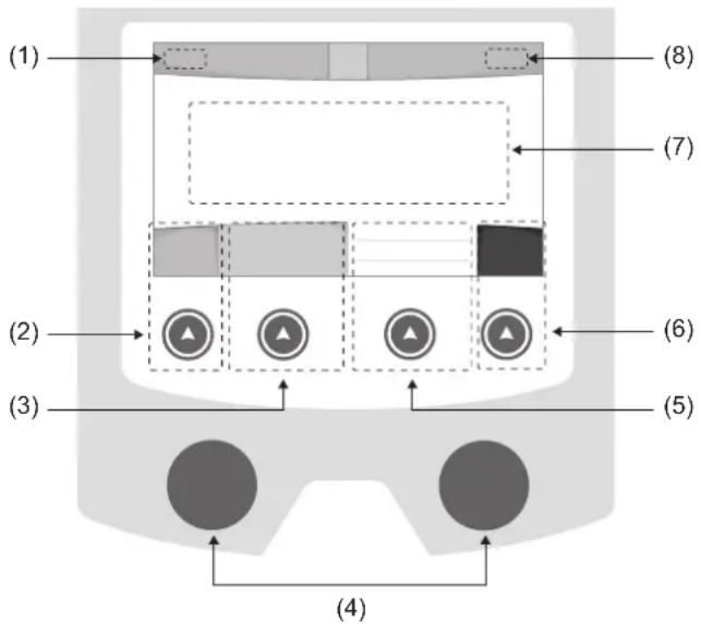
(1)User name/Traceability
(2) Push button n°1: Main menu or return to the previous menu
(3) Push button n°2 : Current Welding Process Settings
(4) Navigation buttons
(5)Push button n^3 :Settings
(6) Push button n°4: Job or Validation
(7) Current settings
(8) Voltage, Current and Power Readings
Main menu
The main menu screen is displayed when the product is first started.
Navigating between the different sections is done using the dials and buttons.
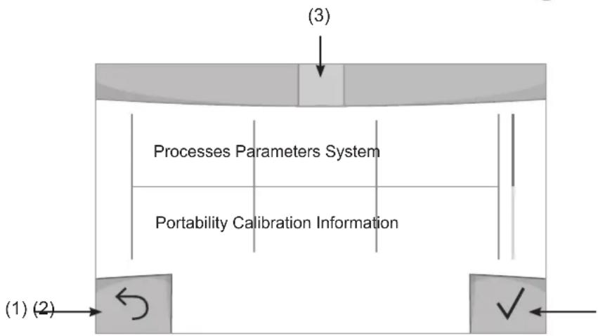
(1) Back
(2) Validation
(3) The current section's computer icon
Processes
Access to some welding processes depends on the product:
MIG-MAG (GMAW/FCAW)
Semi-automatic welding, in a protective gas atmosphere
TIG (GTAW)
Arc welding with non-stick electrode, in a protective gas atmosphere
MMA (SMAW)
Arc welding with coated electrode
Gouging
Air-arc gouging allows a groove to be cut in the metal
Settings (User settings)
Display mode
- Easy: reduced display and functionality (no access to the welding cycle).
- Expert: full display, allows the user to adjust the timing of the different welding cycle phases.
- Advanced: full display, allows the user to adjust all the welding cycle settings.
Language
Choice of the interface language (English, French, German, etc).
Units of measurement
Choice of measurement units: International (SI) or Imperial (USA).
Material naming
European standard (EN) or American standard (AWS).
Brightness
Adjusts the interface screen's brightness (setting from 1 [very dark] to 10 [very bright]).
User Code
Customise the user's access code to safely lock the machine (default 0000).
Tolerance I (current)
Current tolerance control:
OFF: Freely adjustable, the current setting is not limited.
± 0A : no tolerance, current limitation.
± 1A > ± 50A : The setting range at which the user can adjust their current.
Tolerance U (voltage)
Voltage tolerance control:
OFF: freely adjustable, the voltage setting is not limited.
± 0.0V : no tolerance, voltage limiting.
± 0.1V > ± 5.0V : setting range at which the user can vary the voltage.
Tolerance wire speed)
Wire speed setting tolerance (m/min):
OFF: freely adjustable, wire speed setting is not limited.
± 0.0m / min : no tolerance, wire speed control.
± 0.1m / min > ± 5.0m / min : setting range at which the user can vary the wire speed.
Using the machine's System
Naming Device Interface
Information about the device's name and the option to customise it can be reached by pressing on the interface.
Clock
Setting the time, date and format (AM/PM).
Cooling unit
- OFF: The cooling unit is switched off.
- ON : The cooling unit is permanently switched on.
- AUTO : automatic control (activated during welding and deactivated 10 minutes after welding has ended)
PURGE : a function designed to purge the cooling unit or to filling beams, during which the safeguards are disabled (see the cooling unit manual to purge your product safely).
Reset
Pressing 'Reset' will reset the machine's settings:
- Partial: will reset the default value of the present welding process.
- Total: Will reset all the device's configuration data to the factory settings.
Locking
This machine's interface screen can be locked to protect any work in progress and prevent unintentional or accidental changes.
The current settings window can still be modified with the settings chosen in the Settings menu (see previous page). All other functions are inaccessible.
To unlock the interface, press push button #1 and enter your 4-digit user code (default 0000).
Users
The user mode enables the machine to be shared between several users. The first time that the machine is started, it will be in Admin mode. The administrator can create user profiles. Each user has his own setup (mode, setting, process and JOBs etc.) and this cannot be modified by another user. Each user needs a personal four-digit code in order to sign in to the machine.
- The administrator has access to the entire general menu.
- Users have access to a simplified interface. Users do not have the ability to delete information (Tracking, Jobs, User profiles, etc).
User configuration interface (reserved for the administrator).
The left side of the screen lists the users. The administrator has the ability to sort these users by name or by date by quickly pressing button n°2. Pressing this button for a prolonged time will delete the active user(s) instead (although the Admin account cannot be deleted).
On the right side of the screen, you can see the details of all the users previously created with the following information:Avatar, Name, Team No. and Tolerance (%)
Creating a user profile
Press button n°3 to create a new user.
-User:Customise the user's name by pressing push button n^3
-Avatar:Choice of avatar colour
- Team : Assignment of the team number (10 max)
-Usercode:personalaccesscode(default0000)
- Current setting tolerance I:
OFF: freely adjustable, the current setting is not limited.
± 0.0A : no tolerance, limiting the current (not recommended).
± 0.A > ± 50A : Setting interval at which the user can vary their current.
- Voltage setting tolerance U:
OFF: freely adjustable, the voltage setting is not limited.
± 0.0V : no tolerance, limiting the voltage (not recommended).
± 0.1V > ± 5.0V : setting range at which the user can vary the voltage.
- Wire speed setting tolerance (m/min)
OFF: freely adjustable, the wire speed setting is not limited.
± 0.0m / min : no tolerance, limiting the wire speed (not recommended).
± 0.1m / min > ± 5.0m / min : the range of settings at which the user can vary the wire speed.
It is not possible to change the admin name or avatar for the «Admin» user.
Changing a user profile
Select the user on the left side of the screen and press the push button n^4
Selecting users
If one or more user profiles are created, the user block displays all of the machine's users.
Select the user of your choice and press to confirm the choice. You will be asked for an unlock code.
The «Close» feature locks the machine on the user's choice so that no other settings are accessible. This screen remains the same when the machine is switched on (OFF -> ON switch).
User display
The active avatar and username are displayed at the top left of the screen.
Unlocking code
Each user profile is protected by a personal, four-digit code. The default code will be 0000 if not changed. After failing to correctly enter your personal code three times, the interface will be blocked and you will be asked for an unlock code. This code is made up of six digits and cannot be changed. It is: 314159.
Using the machine's Tracking interface
This welding management interface allows you to track/record every step of the welding operation, bead by bead, during any industrial operation. This quality-driven approach ensures high post-production welding quality through analysis, evaluation, reporting and documentation of the recorded welding settings. This feature allows for the accurate and fast collection and storage of data required under EN ISO 3834. This data can be recovered and exported to a USB stick.
1- Start - Creating a tracking system
- Personalise the site's name by pressing push button n°3.
- Sampling interval :
- Hold : No recording of current/voltage values (average along the wire) during welding.
- 250 ms, 500 ms, etc.: Recording of the current/voltage values (average along the wire) every X milliseconds or seconds during welding.
- Options - OFF: simple tracking
- Options - ON : full tracking
Pass counter (ON/OFF)
Weld counter (ON/OFF)
Temperature (ON/OFF): Temperature of the part to be welded at the beginning of the weld bead.
Length (ON/OFF): Length of the wire (units of measurement are displayed according to the choices made in Settings/Units of Measurement).
Variable(s): allows you to add additional personalised information (weight, notes, wire speed, etc.).
Press to start tracking.
Tracking display
At the top left of the screen, the job name and the bead number are displayed (the bead number goes up automatically and cannot be changed).
Identification - Options ON
At the end of each bead, an identification window appears: Pass N°, Weld N°, Part temperature and/or Bead length.
Validation
Confirmation can be done on the HMI or by pressing the torch's trigger.
Stop - Stop tracking
To stop tracking during a welding process, the user must return to the Tracking block and select «Stop».
Export
The recovery of this information is done by exporting the data to a USB stick.
The CSV data can be processed with a spreadsheet program (Microsoft Excel®, Calc OpenOffice®, etc).
The file name is linked to the machine name and serial number.
2- Start -Tracking management
The left-hand side of the screen lists previously created work sites.
The user has the possibility to sort these worksites by name or by date by quickly pressing button n°2. Holding down this button will delete the active job or all jobs.
The right-hand side of the screen shows the details of each of the previously created jobs with the following information: sampling frequency, number of recorded welds, total welding time, welding energy supplied, setup of each weld (process, timestamp, welding time and welding U-1).

Rec
Creation of a tracking system (see previous paragraph)
Start the active site's tracking system
Portability
Import Setup.
Upload the machine settings from a USB memory stick (directory: Removable Disk\PORTABILITY\CONFIG) to the machine. Press and hold to delete the settings on the USB stick.
Export Configuration
Export the machine settings to a USB stick (directory: Removable Disk\PORTABILITY\CONFIG)
Import Job
Importing Jobs to the machine according to the processes available in the USB key's Removable Disk directory.
Export Job
Exporting jobs from the machine to a USB stick according to the processes (directory: Removable Disk|PORTABILITY|JOB). Caution, older jobs on the USB stick may be deleted.
To prevent data loss during data import or export, do not remove the USB flash drive or turn off the machine. The file name is linked to the machine name and serial number.
Calibration
Calib. Speed
Feature designed to calibrate the speed of the motorised reel. The purpose of calibration is to compensate for variations in reel speed in order to adjust the displayed voltage measurement and to refine the energy calculations.
The procedure, once started, is explained with an animation on the screen.
Calibration of the motorised reel speed must be done regularly to ensure optimal welding.
Calib. The Cable
Feature is also dedicated to the calibration of welding accessories such as the torch, cable and electrode holder, as well as the cables and earth clamp. The purpose of calibration is to compensate for the accessories' length changes in order to adjust the displayed voltage measurement and to refine the energy calculations.
The process, once started, is explained with an animation on the screen.
Important : The cable calibration must be repeated each time the torch, harness or earth cable is changed to guarantee optimal welding.
Information
Setup data of the product's system components:
- Model
- Serial number
Device name - Software version
- Job and Synergies (preinstalled user settings) used.
Pressing any push button will exit the information screen.
Job memories and reminders
Can be accessed via the «JOB» icon on the main screen.
The settings in use are automatically saved and remembered the next time you turn on the machine.
In addition to the current settings, it is possible to save and remember so-called «JOB» settings.
There are 500 JOBS for the MIG/MAG and TIG processes, as well as 200 for the MMA process. Data storage is based on the current process settings, the current settings and the user profile.
Job
This JOB mode enables JOBs to be created, saved, remembered and deleted.
Quick-Load - Recall JOBs from the trigger when not welding.
Quick Load is a non-welding JOB recall mode (20 max) and only possible in MIG-MAG and TIG processes.
From a list of previously created JOBs, JOB recalls are done by short trigger presses. All trigger modes and welding modes are supported.
Error codes
The following table shows a non-exhaustive list of messages and error codes that may appear. Carry out these checks and controls before contacting an authorised GYS technician.

If the user needs to open the product, they must turn off the power supply by unplugging the electrical plug and waiting two minutes for safety.
| Error codes | Messages Solutions | |
| 001 | OVER VOLTAGE FAULTCheck the electrical installation | Have your electrical installation checked by an authorised person. |
| 002 | UNDERVOLTAGE FAULTCheck the electrical installation | |
| 005 Earth current fault. | There is a stray current. Check the wiring of the welding accessory (torch, earth clamp, electrode holder, etc.) | |
| 006 | COOLING UNIT FAULTThe cooling unit can no longer be detected. | Check the connection between the undetected cooling unit and the power source. |
| 007 | FLOW RATE FAULTBlocked cooling system | Check the continuity of the coolant flow to the torch. |
| 008 | WATER LEVEL FAULTCheck the water level | Fill the cooling unit's tank to the maximum (with coolant ref. 062511) |
| 009 | COOLING GROUPThermal protection | Wait a few minutes for the cooling unit to cool down.Take care not to exceed the recommended duty cycle for the welding current being used.Ensure that air inlets and outlets are not obstructed. |
| 010 | GENERATORThermal protection | Wait a few minutes for the power source to cool down.Ensure that the recommended duty cycle for the welding current used is not exceeded. Thermal protection Ensure that the air inlets and outlets are not obstructed.Installing a dust filter (ref. 063143). Please note that the dust filter reduces the duty cycle. |
| 011 | FanFan fault | Fan Switch off the power supply by unplugging the electrical plug and check the fan. Ensure that the fan is not blocked. |
| 012 | TRIGGERThe trigger is pressed. | Remove the torch and check that the message is still applicableCheck that the «Gas purge / Wire feed» switch is not obstructed or stuck.Check that the MIG/MAG torch trigger is not obstructed or stuck. |
| 015 | MOTOR Unable to reach the required speed | Check the pressure settings of the motorised reel rollers. Check that the filler wire is not blocked in the torch sheath. If it is Impossible to reach the requested speed, calibrate the speed of the motorised wire reels (Menu «Calibration»). |
| 019 | If overloaded, please check your settings. Release the trigger to clear | Check the power source's settings and the machine's installation (filler wire, rollers, etc.) If the problem persists, carry out an update (Via Planet GYS). |
| 020 | Welding start problem Please check your welding parameters Press and release the trigger to clear. | Check the power source's settings and the machine's installation (filler wire, rollers, etc.) If the problem persists, carry out an update (Via Planet GYS). |
| 024 | USB overload Unplug your USB. | Change the USB stick. |
| - | An internal system error has occurred. Please restart your machine | Restart your machine by turning the machine off and on again. If the problem persists, carry out update (via Planet GYS) |
| - Error during motor calibration Recalibrate the motor reel speed (Menu «Calibration») | ||
| - Error during calibration Recalibrate the welding cables (Menu «Calibration») | ||
| - No more memory space in the machine Delete Jobs to free up the internal storage space. | ||
| - | Unsupported files %s Err %d Continue anyway? | The data on the USB stick is corrupted. |
| - Unable to save to the USB stick | Free up space on the USB stick. If the problem persists, change the USB stick. | |
| - | Number of attempts exceeded. Unlock code required | Enter unlock code: 314159 |
| - Wrong user code | Wrong user code If the personal code is wrong, enter the correct code. By default, this code is 0000. | |
If an unlisted error code appears or your problems persist, contact GYS Customer Service.
Warning icons
The alert icons at the top right of the screen provide you with more information about your product.
| Warning Meaning | |
| DEMO | Alert meaning the machine is in Demonstration mode. Check your electrical installation (mains voltage). |
| Blocked cooling system. Check the continuity of the torch's coolant flow. | |
| End-of-life interface battery. Change the battery (CR2032) and update the [product's date and time (System / Clock). | |
| The fan is not running at the right speed. Check the fan's condition. | |
Export Job (Export von Jobs)
Hac tropon (noIb3ObaTeJIb)
Pekim oTo6paKeHnA
- Easy: ynpaeeHHbI dncnne, MHNmym HhOpamu (HeT IOCTyNA K uKny CBapKN).
- Expert : noJIhBnДиCnIeN, no3BOJraT HAcTpOuTb DnITeNbHOCTb IN BpeM pa3JIuHbIX φa3 UnkJa CBapKn.
- Advanced : nonhoe oTo6paXeHne, n03B0JareT HAcTpnaBaTb BCE npaMeTpbl CBapOCHoro ZIKNa
3bIK
BbI6op 3bIka nHTpePB3uca (qpaHcy3ckn, aHrnnckn, Hemeekn, n T.d.).
EduHnUcBi n3MepeHnA
Bb6op eunnuc n3MepeHna: MeKdyHapOndh (SI) nn DIOJMOBb (USA).
HaimehoBaHne MaTePnaJIOB
Ebponeckne HOpMbENIAmApEnKaHckne (AWS).
RpkocTB
Perynnpyert npkoctb kpaHa nHTeppeca (hactpoka ot 1 (temhbluBEt) do 10 (ouehb npkn)).
KoJ noJIb3OBaTeJIa
HacpoTe KOd Doctyna noIb3ObaTeTn dIy 6NoKIpOBKn erO ceaHcA (no yMOnuHaHIO 0000).
OTKIOHHeI (TOK)
OTKJIOHEHNE NO yCTaHOBKe TOKa:
BbIKI: cbo6oHa HaCTpoKa, TeKUa HaCTpoKa He OrpaHnueHa.
±0A:OTKJIOHeHHe DOnyCTnMo,ФИKCaUNrTOKa
±1A>±50A:INHTepBaHnactpoeK NO KOTOPOMY NOLb3OBaTeJIb MOXETN3MeHrTb TOK.
OTKNoHeHne U (HaPjaKeHne)
OTKIOHeHne no HacTpoKe HanpJxHeHn:
BbIKI: cbo6oHa HaCTpoKa, TeKUaHaCTpOka He OrpaHnueHa.
±0.0V:OTKNOHeHHe DOnyCTnMo,ΦnKCaunHaPraJKeHHa
±0.1V>±5.0V:INHTepBaJI HAcTpoE KIO KOtOpOMY NOJb3ObaTeJIb MOKeT 3MeHЯrTb HApPjaKeHne
I3MeHHeH npOoHnI NOb3OBaTeJIa
Bb6epnte noIb3oBaTeJIaB BoB YacTn 3KpaHa N HaxMnte KhoNky n°4.
Bb6op noJb3OBaTeJra
Ecn co3dAn OINH (nH HeckonbKO) noB3OBaTeJe, B 6JIOKe nOJB3OBaTeJe OTo6paKaIOTc Bce nOJB3OBaTeJI annapata.
Bb6epnte HxHoro nonb3oBaTeIHa hKMTe Ha TIObI NOITBepnTb. NOTpe6yETc BBOd KOA 6LOKINPOBKn ΦyHKUg «3aKpbITb» No3BOJnEe 3aKePnITb MaunHy nOIpeneHHbx NOnb3oBaTeJe, HnKaKe Ipyrne npaMeTpbl He 6dyT IOCTyInHb DaHHa INDkaCuaN IeHTuHaa Korda MaunHa BkHoueHa (peeknoateJB OFF -> ON)
OTo6paXeHne NOIb3OBaTeJIa
CbepyB neBOJ yactn 3kpaHa oTo6pKaaeTc aBaTAP NIMA KAtNBHO rONb3OBaTeJIa.
Ko6JOKnPOBKn
KaKdb npoФnIb noIb3OBaTeJIra 3aunuH eN nepcoHaIbHbIM KOD m3 4x uΦp. Be3 nepcoHaIN3aUN, NO yMONUHIO 3OT kOd 0000 Nocne 3 oW6OuHbIX nONbITOK BAUI nepcoHaJIbHbIK KOd INHTeppeCa 3aBLOkpyETcN INOTpe6yET KOD pa36LokPobKn DaHHbKOd COCTOIT n3 6 uΦp N He MoDnФnucpyEmbl. KoD: 314159.
OTcJIeJINBaEmOCTb
3TOT INTEPpeHc npaBHeN CbapKo N03BONeET OTCJeKbA Tb/3aINCbBa Tb BCE 3TaIb CBAPKn 3a WOB BO Bpemn3ROTOBHeHnpomblneHHoro n3dEInr. 3Ta MeToDnka ynpaBHeHn KaueCTBOM oBeCneuBAeT KaueCTBO CBAPKn nocpePOn3BOJCTBa, YTO NO3BOJAE T PObEcTN aHaJIIN3, OCEHKy, OTYeTHOCb I DOKyMeHTaUIO COxpaHeHHbIX CBAPOHyBX napaMeTpOB. 3Ta fynKcNoHaJIbHOCTb oecneuBaet ToHbI N 6bICTpbI c6Op, a TaXke coxpaHeHne DaHHbIX, 3aPaunBaembIX B pAMkax cTaNapTa EN ISO 3834. BocctahOBHeHne 3tNx daHHbx BO3MOxH Nope3 KcNopt Ha USB-KnOu.
1- Start -Co3dahne OTCJexKnaeMoCTn
HactpoTe NmI NOJb3oBaTeNIAHxAB KHOIny n°3.
-ИntepBaJI BB6OpKn:
-Hold:OTcyTCTBnE3aHnCn3NaueHnToKa/HanpJxKeHn(cpeHHe 3NaueHne no npOBOy) BO BpeM CBapKn.
-250MC,500MCnT.D.:3aIncb 3HaueHn ToK/HanpJxKeHne (cpeHee 3HaueHne no npoBdy) KaXdyU X MmNcEkyHy nnn CekyHy BO BpeM CBapKn.
- Onpui - OFF : npocTaT aOCTeKnBaemocTb
- OnuIN - ON: noJHoueHHa OTCneKnBaemocTb CuetTK npoxoob (ON/OFF)
CteTcK CBapKn (ON/OFF)
TemnepaTypa (ON/OFF): TemnpaTypa cBapnBaemOn DeTaN B Hauane CBapOuHoro 1Ba.
Динна (ON/OFF) :Динна унура (eДинць iЗмереня OTOбрахаOTСВ COOTBeTCTBи C BыборOM, cdeЯHHbIM B HactpoIGN/EДинць iЗмереня).
IpeMeHHa(ble): no3BOJnEeT do6abTb dOIOHnTeBHyIO NOJIb3OBaTeBcKyIO INΦopMaUIO (Bec, aHHotaM, CKOpocTb pNOBOJOKN I T.D.)
HaxMnte VTO6bHaayatb OTCneXnBaHne.
OTo6paXeHne npocJIeKINBaEMoCTn
B BepxHem IeBOM yIy 3kpaHa OTo6paKaIOTCa H3BaHHe cExa N HOpE npOBoJa (HOpE npOBoJa BBOHTcA ABTomAtueckn H He MoXeT 6bITb N3MeHeH).
INDnkaun -OnuON
B KOHcE KAKDOrO 1Ba NOBnTnФkaun: HOpE npoxoHa, HOpE cbapHoro 1Ba, TempepaTypa 3aToTOBkn I/III nIINHa npoOda.
PntBepKdeneHne
IoTBePxJdHHe MoKTe 6bItb BbInOnHeHa Ha IHM nn HaxaTneMa TprIrrep ropeJIKN.
CTon - OctaHOBka OTCJIeXINBAHnA
YTo6bI OCTaHOBtB OTCJExnBaEMocTb Ha 3TaNE CBapKn, NOnb3ObaTeNb DOJKeH BepHyTbC8 B 6NoK «OTcJexnBaEMocTb» I BB6paTb «OCTaHOBtB».
3KcnpTnpoBaTb
Ionyehne 3ToHnHOpMaun npOn3BODITcnyTEM kCnOpa daHHbX Ha KIOU USB.
Ha3eaHue doKymehma coombeemcmyem Ha3eaHuO Maunhbu e ee cepuHomy Homepy.
2- Start - Co3dHne oTcJIeKINBaEMocTn
B JEBOuactn 3KpaHa nepeucnIeHb paHee co3aHHbI cTPOTeIbHbI pNOUaKn.
IOnb30BATEnb IMeET BO3MOXHOCTb COptnPOBaTb NO HA3BAHIO IIN NO DaTe KOpOTKO HAKAB HA KHONKY KJIaBNaTypbI n°2. DOnrOe HAKATNE Ha 3Ty KHONKY N03BOJRAET ydaJIHTb AKTNBBHbI pa6Ooee MeCTO IIN BCE pa6OuINE MeCTA.
B npaboi yactn 3kpaHa moKHO npocMoTeB deTaN KaKDoRo n3 paHee co3daHbIX pa6OuX MeCt CO cneDuOe HnΦopMauné: yactota Bb6OpKn, KOInueCTBO coXpaHeHHbIX WBOB, oBua JpOdoJHKntbHocTb CBapKn, KOHpyraunie npaMeTPOB KaKDoRo IBa (MeToD CBAPKn, ABToMaTHueCKoe IpocTaBHeHne DaTbI N BpeMeHN, PpOdoJKNtBbHocTb CBAPKn u-1 CBapKn).

3anncb
C03dHHe OTCnEJKBaEMoCTb (cm npdeIbIyIuI npaparpaΦ)
3anyckOTcneKnBaEMOCTn aKTNBHOrO texa
MôşnlbHocTb
3arpy3ntb KoHdnpyrpaunIO
3arpyka KOHnrgpaunm Maunhblc USB-hocnte (Kataor:Cbemhduuck \MobunbHocmb \Ha mauuHy. dntelbHoe Haxatne Ha knaBny dyanrE hactpoKn c USB kapTbi.
3KcnpTnpoBaTb KoHpNpyaUIO
3Kcnpot KOHpyaun MaunnHa USB KapTy (kataor: CbeMbu duCK MObunbocmb Hacmpouku)
3arpy3ntbJob
I Mnopt Jobs B COOTBETCTBn C npoceDpyamn, HaxoJauuMncs B KaTanore Removable disk \ Portability c USB-Knoua Ha KOMnbTOpe.
3KcnpTnpoBaTb Job
3KcnpT 3aAHHn n3 annapata Ha USB hakonntenb B COOTBETCTBn C npoceDypamn (kataor: CbeMHbI duckMobunbHocmb Job)
Bhumaue, cmapbte 3adaunha USB Kapme, mozym 6bim ydaenhebl.
UTo6bI n36exaTb notepn daHbix npn mnpTe nIn 3KcnpTe daHbIX, He n3BneKaite USB-hakonnte Ih He bIKIOaHTe annapat. Ha3BaHue dokymehma coomemcmeyem ha3BaHuO MaunHbI u ee cepuHOMy Homepy.
KannibpoBka
KaJIb6poBka CkOpcTb
Функця,прднэзнayehня Длг Калббвкссokocm Мexан3ma nodauyn npobOLOKn. Zeью калббвкн raBnreTcKOMнeнcaци n3MeHEni DnHb CBapouhbx Kabene C Tem, yTo6bl OTKoppeKTnpoBaTb 3amep apnunpyemoro HanpaJKeHn i uIyUnuTb paCet eHepn. Pocne 3anycka npocecca, OH oTo6paKaTeCn Ha 3kpaHe cAnMaunei.Длг obecneueHn ONtumalbHo CBapkn Heo6xOdmo nepnoDnueckn npobOOnbTk KalnbSbovk cykopocTn BpaUeHn6apabana DBnraTeJIa.
KajnbpoBka Ka6eJia
3TOT pexnmpedHa3aHcEN nKan6pOBN TaKIN CbapOHybIX aKceccyapOB, KaK rOpEnKa, Ka6B + 3NeKtpoDoepkataeNB KAb+ 3axm MaccbI. CeIbIO KAIn6pOBKn RaJIaTeC KOMneHcaUNI N3MeHeHN dINHBcBapOHybIX Ka6BeNc TEm, YTO6bl OTkoppeKtnpoBaTb 3aMep aHmHpyemoro HAnpJxHnIu IyUWHTb paCET3Heprnn. Pocne 3anycka npouecca, OH OTo6paXaeTcH aKpane c AhMaunie.
BHIMAHHE: KaIb6pOBKa KaBEna DoJIkHa npOBoDnTbcra KaKdb pa3 npn 3aMeHe rOpENK, KryTa nn KaBEna 3a3eMJIeHn IJRA ObcneueHn ONTImaJIbHO CBapKn.
HΦopMaçña
CoxpaheHne n Bbl3OB n3 namTn konhngypaun JOBs
Дocупен чере зйонку «JOВ» на ос hobом заразе.
Bo BpemnnoB3OBAHnnaPametpbA bTOMaTHueckn COxpaHnOTc n BOCtHaBaHnBaHTc pni CNeDyUoEeM BKIOUeHN.
ПOMМО TEKUYUxN napametpoB, moXHO coXpaHrTb N Bb3bBaTb KOHpMrypaUm «JOB».
Ectb 500 KoHpypaun JOBS nra metoob Mf/Ma n Tn n 200 dna MMA XpaHeHne ochoBaHo ha napameTpax Tekyuero npouceca, Tekyuix hactpoek n npoqnil noh3OBateia.
JOB
PeknM JOB no3BONJrEe Co3DaBaTb, CoXpaHrTb, ydaJIbN Bbl3bIbA Tb KOHpMrypaun JOB.
QUICK LOAD-BbI3OB KOHΦnrgpaun JOBc nOmoUHO Tpnrrepa BHe CBapKn.
Quick Load - 3TO peKIM BblOBA KOHΦnIpyaun JOB (MaKc. 20) BHe CBapOuHoro IpoUecca n KOTOpbI BO3MOKeH TOJIbKO B peKIMe MIG-MAG n TIG.
Bb3OB KOHpyaun JOB n3 npedBaupTeNbHO CO3daHnHO cncsKa KOHpyraunm JOB, npou3BOuNTcKoPOTkM haxaTneM Ha Tpnrrep. Bce TprrrepHbe pexMbI n peXMBI CBapKn noDepxNBAOTc.
KoД oшибкn
B cIeDyUoSe Ta6JIue npBVeDeH HEnOJIbI CNICOK COO6eHn I KOIOB OUI6OK, KOTOpBle MOrY T NOBtbcra.
BbnoJHnTe 3Tn npOBepK IN KOHTpOJIb nepeI TEM, KaK Bbl3BaTb ABTOPn3OBAHHOrO cepBnCHORo cneuaHnCTa GYS.

Ecnn noIb3ObaTeHNO Heo6xOaHMO BCKpbITb 3dene, 68a3aTeNbHO Heo6xOaHMO OTKIOuHTb annapat OT po3eTKN, nnooxdaTb 2 MNHyTb IJy 6e0NaChOCTN.
Ecni noBnreTc H3aperncTpnpoBaHHbIKoD Oun6Kn NIn Baun npo6neMbI He nCye3aOT, CBxntecb c SAV GYS
Иконки педунрекдени (Warning)
3NaUpNpeDpynpExHnB BepxHe npaBoyacTn 3KpaHa daIOT HΦopMaunO BaWem npoDyKe.