
SuperFinish 33 Plus - Paint spray WAGNER - Free user manual and instructions
Find the device manual for free SuperFinish 33 Plus WAGNER in PDF.
| Product Type | Electric Airless Paint Sprayer |
| Brand | Wagner |
| Model | SuperFinish 33 Plus |
| Technology | Airless (airless) |
| Max. Service Pressure | 25 MPa (250 bar) |
| Max. Flow Rate | 4.3 L/min |
| Flow at 12 MPa (120 bar) | 3.8 L/min (with water) |
| Max. Nozzle Size | 0.033 inch (0.84 mm) |
| Max. Product Viscosity | 25,000 mPas |
| Max. Product Temperature | 43 °C |
| Weight (empty) | 50 kg |
| Power Supply | 230 V ~, 50 Hz, 10.7 A |
| Power Consumption | 2.2 kW |
| Protection Rating | IP 54 |
| Power Cable Length | 6 m |
| Appliance Outlet (max load) | 230 V, max. 1200 W |
| Hydraulic Oil | Divinol HVI 15, 1.1 L |
| Max. Tire Pressure | 0.2 MPa (2 bar) |
| Sound Pressure Level | ≤ 76 dB(A) |
| Gun Vibration | < 2.5 m/s² |
| Pump Type | Diaphragm pump |
| Feed Systems | Suction system (rigid/flexible) or top container (5 L/20 L) |
| Application Areas | Varnishes, dispersions, latex paints, anti-corrosion, fireproofing, etc. |
| Recommended Maintenance | Cleaning after each use, annual inspection by a specialist |
Frequently Asked Questions - SuperFinish 33 Plus WAGNER
User questions about SuperFinish 33 Plus WAGNER
0 question about this device. Answer the ones you know or ask your own.
Ask a new question about this device
Download the instructions for your Paint spray in PDF format for free! Find your manual SuperFinish 33 Plus - WAGNER and take your electronic device back in hand. On this page are published all the documents necessary for the use of your device. SuperFinish 33 Plus by WAGNER.
USER MANUAL SuperFinish 33 Plus WAGNER
10 REPARATUREN AM GERÄT 17
1.2 EXPLOSIONSSCHUTZ

Gefahr
3.4 TRANSPORT
3.6 WERKZEUGBOX
4.5 STECKDOSE AM GERÄT
10 REPARATUREN AM GERÄT
Gefahr
10.2 EINLASSVENTIL
Montage
10.4 DRUCKREGELVENTIL
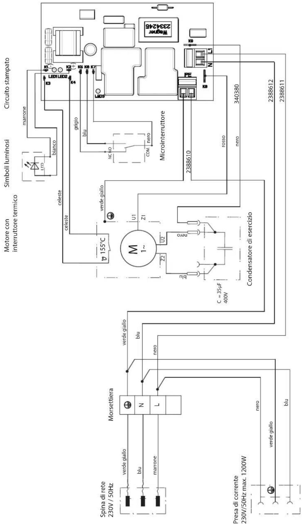
10.7 SCHALTPLAN
EMPFEHLUNG

TEMPSPRAY
TempSpray H 226 / H 326
HEA - DÜSEN FÜR NEBELARMES SPRITZEN MIT NIEDERDRUCK

11.3 ERSATZTEILLISTE HOCHDRUCKFILTER (ZUBEHÖR)
go.wagner-group.com/profi
PRÜFUNG DES GERÄTES
www.wagner-group.com/profi-guarantee.
Division Professional Finishing
Otto Lilienthal Strasse 18
88677 Markdorf
Translation of the original operating instructions
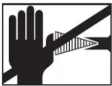
WARNING!
Attention, danger of injury by injection!
Airless units develop extremely high spray pressures.
  Danger Danger | |
| 1 | Never bring fingers, hands or other body parts into contact with the spray jet!Never point the spray gun at yourself, other persons or animals.Never use the spray gun without spray jet safety guard.Do not treat a spray injury as a harmless cut. In case of injury to the skin by coating material or solvents, consult a doctor for quick and correct treatment. Inform the doctor about the coating material or solvent used. |
| 2 | The following points are to be observed in accordance with the operating manual before every start-up:Faulty units may not be used.Secure a Wagner spray gun with the securing lever at the trigger guard.Ensure earthing.Check the permissible operating pressure of the high-pressure hose and spray gun.Check all the connecting parts for leaks. |
| 3 | Instructions for regular cleaning and maintenance of the unit are to be observed strictly.Observe the following rules before any work on the unit and at every working break:Relieve the pressure from the spray gun and high-pressure hose.Secure a Wagner spray gun with the securing lever at the trigger guardSwitch the unit off. |
Ensure safety!
Contents
1 SAFETY REGULATIONS FOR AIRLESS SPRAYING 40
1.1 Flash point ____
1.2 Explosion protection ____
1.3 Danger of explosion and fire from sources of ignition during spraying work ____ 40
1.4 Danger of injury from the spray jet ____ 40
1.5 Secure spray gun against unintended operation _ 40
1.6 Recoil of spray gun 40
1.7 Breathing equipment as protection against solvent vapors ____ 40
1.8 Prevention of occupational illnesses 40
1.9 Max. operating pressure 41
1.10 High-pressure hose
1.11 Electrostatic charging (formation of sparks or flames) ____ 41
1.12 Use of units on building sites and workshops ____ 41
1.13 Socket at the unit 41
1.14 Ventilation when spraying in rooms ____ 41
1.15 Suction installations
1.16 Earthing of the object 41
1.17 Cleaning the unit with solvents 41
1.18 Cleaning the unit 41
1.19 Work or repairs at the electrical equipment ____ 41
1.20 Work at electrical components 42
1.21 Setup on an uneven surface 42
2 GENERAL VIEW OF APPLICATION 42
2.1 Application ____
2.2 Coating material
2.2.1 Coating materials with sharp-edged additional materials ____ 42
2.2.2 Two-component coating material 42
2.2.3 Filtering 43
3. DESCRIPTION OF UNIT 43
3.1 Airless process ____
3.2 Functioning of the unit 43
3.3 Explanatory diagram 44
3.4 Transportation 44
3.5 Trolley backfitting
3.6 Tool box
3.7 Technical data
4 STARTUP 47
4.1 Unit with suction system 47
4.2 unit with upper hopper 47
4.3 High pressure hose and spray gun 47
4.4 Connection to the mains network 47
4.5 Socket on unit 48
4.6 Cleaning preserving agent when starting-up of operation initially ____ 48
4.7 Ventilate unit (hydraulic system) if the sound of 40 inlet valve is not audible ____ 48
4.8 Taking the unit into operation with coating material ____ 48
5 SPRAYING TECHNOLOGY 49
6 HANDLING THE HIGH-PRESSURE HOSE 49
7 INTERRUPTION OF WORK 49
8 CLEANING THE UNIT 50
8.1 Cleaning the unit from the outside ____ 51
8.2 Suction filter 51
843 High-pressure filter ____
8.4 Cleaning the Airless spray gun 52
9 SERVICING 52
9.1 General servicing 52
9.2 High-pressure hose
410 REPAIRS AT THE UNIT 53
10.1 Inlet valve Pusher 53
10.2 Inlet valve 53
10.3 Outlet valve 54
10.4 Pressure control valve 54
10.5 Replacing the power cable 55
10.6 Typical wear parts 55
10.7 Connection diagram 56
10.8 Remedy in case of faults 57
421 SPARE PARTS AND ACCESSORIES 58
11.1 Super Finish 33 PLUS accessories 58
11.2 Spare parts list Super Finish 33 PLUS ____ 66
11.3 Spare parts list high-pressure filter 68
11.4 Spare parts List Trolley 68
11.5 Spare parts list suction system 69
11.6 Spare parts list hopper 5 litres ____ 70
11.7 Spare parts list hopper 20 litres ____ 70
Testing of the unit 71
Important information on product liability ____ 71
Note on disposal 71
Guarantee declaration 71
CE - declaration 72
European service network 148
1 SAFETY REGULATIONS FOR AIRLESS SPRAYING
All local safety regulations in force must be observed.
The following sources are just a sample of those containing safety requirements for Airless spraying.
a) The European Standard „Spray equipment for coating materials – safety regulations „ (EN 1953).
The following safety regulations are to be observed in order to ensure safe handling of the Airless high-pressure spraying unit.
1.1 FLASH POINT

Only spray coating materials with a flash point of 21 °C or higher.
The flash point is the lowest temperature at which vapors develop from the coating material. These vapors are sufficient to form an inflammable mixture over the air above the coating material.
1.2 EXPLOSION PROTECTION

Do not use the unit in work places which are covered by the explosion protection regulations. The unit is not designed to be explosion protected. Do not operate the device in explosive areas (zone 0, 1 and 2). Explosive areas are, for example, places where paints are stored and locations in direct proximity to the object being sprayed. Keep the device at least 3 m from the object you are spraying.
1.3 DANGER OF EXPLOSION AND FIRE FROM SOURCES OF IGNITION DURING SPRAYING WORK

There must be no sources of ignition such as, for example, open fires, lit cigarettes, cigars or tobacco pipes, sparks, glowing wires, hot surfaces, etc. in the vicinity.
1.4 DANGER OF INJURY FROM THE SPRAY JET

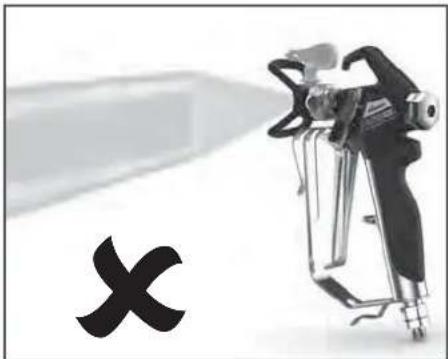
Attention, danger of injury by injection! Never point the spray gun at yourself, other persons or animals.
Never use the spray gun without spray jet safety guard.

The spray jet must not come into contact with any part of the body.
In working with Airless spray guns, the high spray pressures arising can cause very dangerous injuries. If contact is made with the spray jet, coating material can be injected into the skin. Do not treat a spray injury as a harmless cut. In case of injury to the skin by coating material or solvents, consult a doctor for quick and correct treatment. Inform the doctor about the coating material or solvent used.
Always secure the spray gun when mounting or dismounting the tip and in case of interruption to work.
1.6 RECOIL OF SPRAY GUN

When using a high operating pressure, pulling the trigger guard can effect a recoil force up to 15 N.
If you are not prepared for this, your hand can be thrust backwards or your balance lost. This can lead to injury.
1.7 BREATHING EQUIPMENT AS PROTECTION AGAINST SOLVENT VAPORS
Wear breathing equipment during spraying work.
A breathing mask is to be made available to the user.
1.8 PREVENTION OF OCCUPATIONAL ILLNESSES
Protective clothing, gloves and possibly skin protection cream are necessary for the protection of the skin.
Observe the regulations of the manufacturer concerning coating materials, solvents and cleaning agents in preparation, processing and cleaning units.
The permissible operating pressure for the spray gun, spray gun accessories, unit accessories and high-pressure hose must not fall short of the maximum operating pressure of 25 MPa (250 bar or 3625 psi).
1.10 HIGH-PRESSURE HOSE

Attention, danger of injury by injection! Wear and tear and kinks as well as usage that is not appropriate to the purpose of the device can cause leakages to form in the high-pressure hose. Liquid can be injected into the skin through a leakage.
- High-pressure hoses must be checked thoroughly before they are used.
- Replace any damaged high-pressure hose immediately.
- Never repair defective high-pressure hoses yourself!
- Avoid sharp bends and folds: the smallest bending radius is about 20 cm.
- Do not drive over the high-pressure hose. Protect against sharp objects and edges.
- Never pull on the high-pressure hose to move the device.
- Do not twist the high-pressure hose.
- Do not put the high-pressure hose into solvents. Use only a wet cloth to wipe down the outside of the hose.
- Lay the high-pressure hose in such a way as to ensure that it cannot be tripped over.

Only use WAGNER original-high-pressure hoses in order to ensure functionality, safety and durability.
1.11 ELECTROSTATIC CHARGING (FORMATION OF SPARKS OR FLAMES)

Electrostatic charging of the unit may occur during spraying due to the flow speed of the coating material. These can cause sparks and flames upon discharge. The unit must therefore always be earthed via the electrical system. The unit must be connected to an appropriately-grounded safety outlet.
An electrostatic charging of spray guns and the high-pressure hose is discharged through the high-pressure hose. For this reason the electric resistance between the connections of the high-pressure hose must be equal to or lower than 1 MΩ.
1.12 USE OF UNITS ON BUILDING SITES AND WORKSHOPS
The unit may only be connected to the mains network via a special feeding point with a residual-current device with INF ≤ 30 mA. An upstream circuit breaker (fuse) with 16 A (B or C characteristics) is required.
1.13 SOCKET AT THE UNIT
Do not load the socket with more than 1200 Watt. Unroll any connected cable drum completely.
1.14 VENTILATION WHEN SPRAYING IN ROOMS
Adequate ventilation to ensure removal of the solvent vapors has to be ensured.
1.15 SUCTION INSTALLATIONS
The are to be provided by the unit user in accordance with the corresponding local regulations.
1.16 EARTHING OF THE OBJECT
The object to be coated must be earthed.
(Building walls are usually earthed naturally)
1.17 CLEANING THE UNIT WITH SOLVENTS

When cleaning the unit with solvents, the solvent should never be sprayed or pumped back into a container with a small opening (bunghole). An explosive gas/air mixture can arise. Only use an earthed container made from metal.
1.18 CLEANING THE UNIT

Danger of short-circuits caused by water ingression!
Never spray down the unit with high-pressure or high-pressure steam cleaners.
1.19 WORK OR REPAIRS AT THE ELECTRICAL EQUIPMENT
These may only be carried out by a skilled electrician. No liability is assumed for incorrect installation.
1.20 WORK AT ELECTRICAL COMPONENTS
Unplug the power plug from the outlet before carrying out any repair work.
1.21 SETUP ON AN UNEVEN SURFACE
The front end must always point downwards in order to avoid sliding away.
If possible do not use the unit on an inclined surface since the unit tends to wander through the resulting vibrations.
2 GENERAL VIEW OF APPLICATION
2.1 APPLICATION
Super Finish 33 PLUS is an electric driven unit for the airless atomization of different painting materials. Also it is able to feed the internal feeded paint roller, which is available as accessory. Super Finish 33 PLUS is made for jobs in the workshop and on the building site.
The device output of the Super Finish 33 PLUS is designed so that it can be used to process dispersions for small and large objects, as well as for corrosion and flame protection.
When painting, the device is suitable for all kinds of typical painting jobs, e.g.:
doors, door frames, balustrades, woodencladding, fences, radiators (heating) and steel parts.
We recommend using the top container for paintwork.
2.2 COATING MATERIAL
Dilutable lacquers and paints or those containing solvents, two-component coating materials, dispersions, latex paints, façade paints, roof and attic coatings, fire and corrosion protection material.
No other materials should be used for spraying without WAGNER's approval.
| Pay attention to the Airless quality of the coating materials to be processed. |
The unit is able to process coating materials with up to 25,000 mPas. If highly viscous coating materials cannot be taken in or the performance of the unit is to low, the paint must be diluted in accordance with the manufacturer's instructions.
| Attention: Make sure, when stirring up with motor-driven agitators that no air bubbles are stirred in. Air bubbles disturb when spraying and can, in fact, lead to interruption of operation. |
2.2.1 COATING MATERIALS WITH SHARP-EDGED ADDITIONAL MATERIALS
These particles have a strong wear and tear effect on valves and tips, but also on the heating hose and spray gun. This impairs the durability of these wearing parts considerably.
2.2.2 TWO-COMPONENT COATING MATERIAL
The appropriate processing time must be adhered to exactly. Within this time rinse through and clean the unit meticulously with the appropriate cleaning materials.
2.2.3 FILTERING
Sufficient filtering is required for fault-free operation. To this purpose the unit is equipped with a suction filter (Item 1) and an insertion filter in the spray gun (Item 2). Regular inspection of these filters for damage or soiling is urgently recommended.
A high-pressure filter (Item 3) -available as accessory- is rising up the filtering surface and will make the work more comfortable.
3. DESCRIPTION OF UNIT
3.1 AIRLESS PROCESS
The main area of application are thick layers of highly viscous coating material.
At the Super Finish 33 PLUS unit a diaphragm pump takes in the coating materials and transports it via a high-pressure hose to the spray gun with the airless tip. Here the coating material atomizes since it is pressed through the tip core at a maximum pressure of 25 MPa (250 bar, 3625 psi). This high pressure has the effect of micro fine atomisation of the coating material.
As no air is used in this process, it is described as an AIRLESS process.
This method of spraying has the advantages of finest atomisation, cloudless operation (depending of a correct unit adjustment) and a smooth, bubblefree surface. As well as these, the advantages of the speed of work and convenience must be mentioned.
3.2 FUNCTIONING OF THE UNIT
The following section contains a brief description of the technical construction for better understanding of the function:
Super Finish 33 PLUS is an electrically driven high-pressure paint spraying equipment.
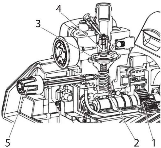
The electric motor drives the hydraulic pump via planetary gears (1). A piston (2) is moved up and down so that hydraulic oil is moved under the diaphragm (3) which then moves.
In detail:
The downwards movement of the machine opens the disk inlet valve (4) automatically and coating material is sucked in.
During the upwards movement of the diaphragm, the coating material is displaced and the outlet valve opens while the inlet valve is closed.
The coating material flows under high pressure through the high-pressure hose to the spray gun and is atomized when it exists from the tip.
The pressure control valve (5) limits the set pressure in the hydraulic oil circuit and thus also the pressure of the coating material.
A pressure change when the same tip is used also leads to a change in the amount of paint atomized.
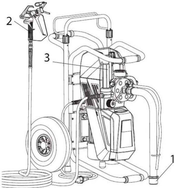
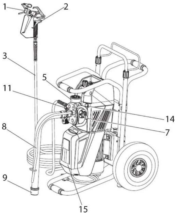
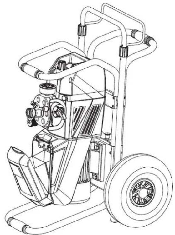
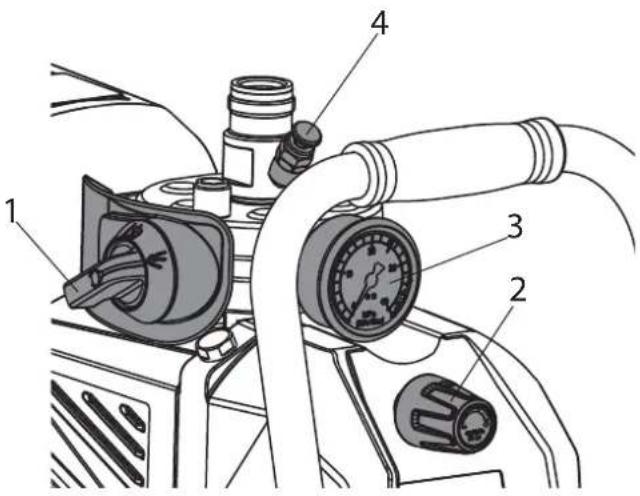
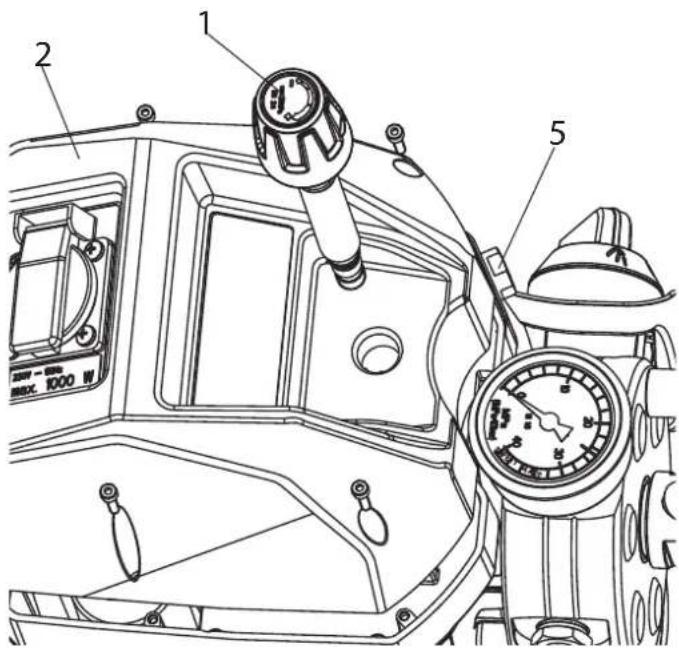
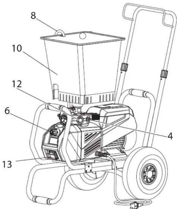
3.3 EXPLANATORY DIAGRAM
1 Tip guard with airless tip
2 Spray gun
3 High-pressure hose
4 Connection for high-pressure hose
5 Pressure gauge
6 Pressure control valve
7 Multifunction switch
Symbols (shown in the recess of the switch):
0 OFF

ON / Circulation

ON / Spraying
8 Return tube
9 Suction tube
10 Hopper
11 Inlet valve button
12 Outlet valve
13 Socket, max. load 1200 Watt
14 Oil measuring stick
15 Tool box
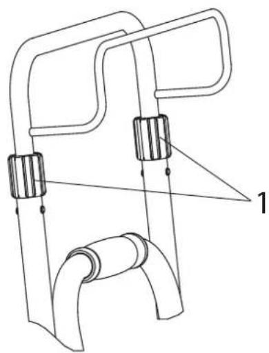
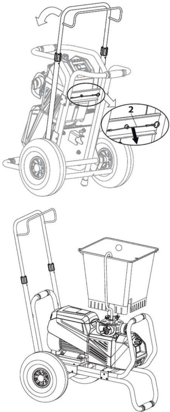
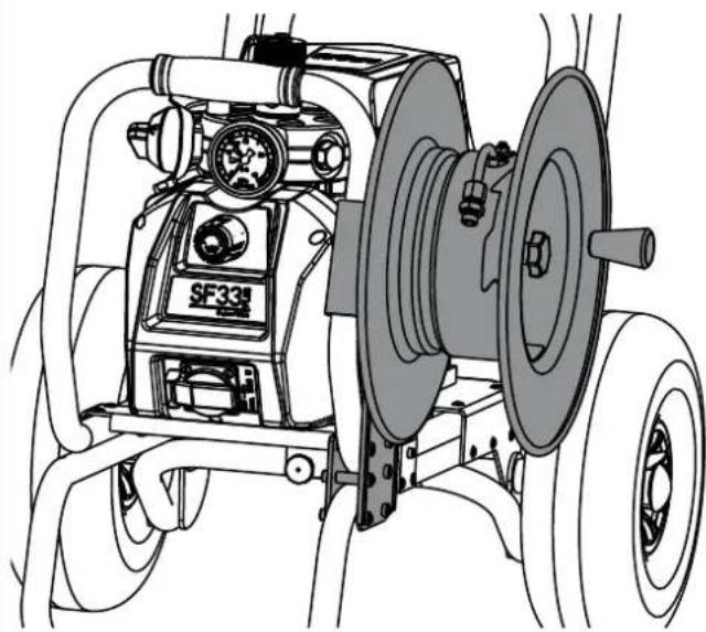
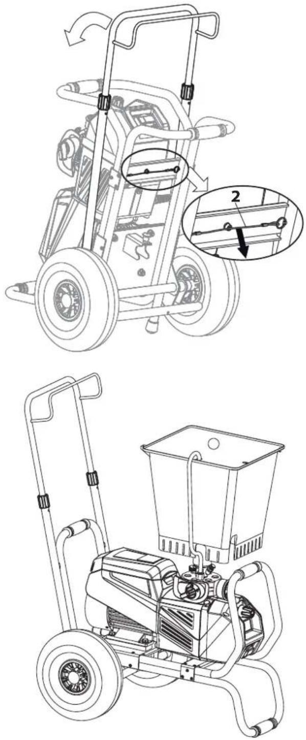
3.4 TRANSPORTATION
Unroll high-pressure hose and lay it over the shaft.
Loosen terminal sleeves (item 1) on the shaft ( open). Extract shaft to the desired length. Tighten terminal sleeves again by hand ( closed).
Transportation in vehicle
Secure the unit in the vehicle by means of suitable fasteners. The device can be placed on its side if necessary. In this case, please ensure that no attachments can be damaged. Attention: Paint or solvent residues can escape from the connections!
Before start with the backfitting, pull of main plug of socket, disassemble suction system and high pressure hose. Do not trap the mains cable.
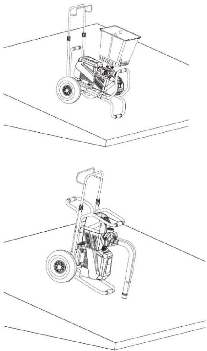
a) For changing to vertical mode
- Pull out the screen (1) and tilt the handle until it audibly engages in the end position.
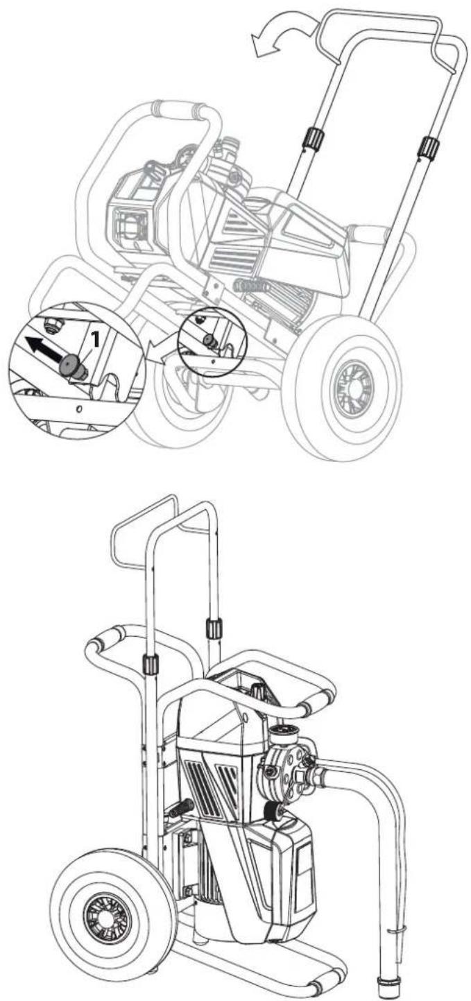
b) For changing to horizontal mode
- Pull the cord (2) and tilt the handle until it audibly engages in the end position.
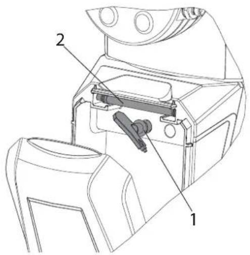
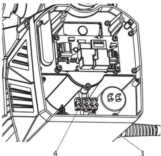
3.6 TOOL BOX
The SF 33 comes with an integrated tool box which can be opened both with vertical and horizontal setup. As well as providing sufficient storage space for all of the tools required, the box also has slots for three nozzles (1) and two filters (2). The internal pocket, held in place with Velcro fasteners, can be removed if required.
| The tool box has a magnetic closure mechanism. Do not place any credit cards, magnetic storage media or similar objects in the box since doing so may damage them or cause data loss. |
3.7 TECHNICAL DATA
Super Finish 33 Plus (Type: D701C)
Voltage: 230 V AC, 50 Hz
Fuses : 16 A time-lag
Unit connecting line : 6 m long, 3 x 1.5 mm 2
Max. current consumption: 10.7 A
Degree of protection : IP 54
Rated input of device: 2.2 kW
Max. operating pressure : 25 MPa (250 bar)
Max. volume flow : 4.3 l/min
Volume flow at 12 MPa
(120 bar) with water : 3.8 l/min
Max. temperature of the
coating material : 43 °C
Max. nozzle size: 0,033 inch - 0,84 mm
Max. viscosity : 25,000 mPas
Empty weight: 50 kg
Hydraulic oil filling quantity : 1.1 liter, Divinol HVI 15
Max. tyre pressure: 0.2 MPa (2 bar)
Plug connection on device: 230 Volt \~, 50 Hz
max. connection: 1200 W
Max. vibration at the spraygun: lower than 2.5 m/s2
Max. sound pressure level: 76 dB (A)*
*Place of measurement: 1 m distance from unit and 1.60 m above floor, 12 MPa (120 bar) operating pressure, reverberant floor
4 STARTUP
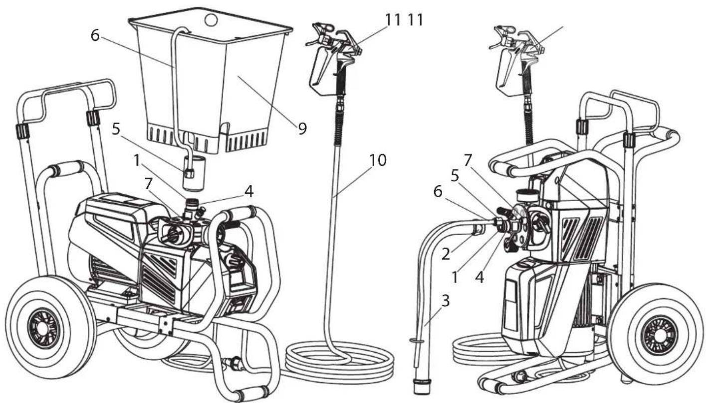
4.1 UNIT WITH SUCTION SYSTEM
- Ensure that the sealing surfaces of the connections are clean.
Ensure that the red inlet (1) is inserted in the coating material inlet (4).
- Use the enclosed 41 mm wrench to screw the union nut (2) at the suction hose (3) onto the coating material inlet (4) and tighten it.
- Screw the union nut (5) at the return hose (6) to the connection (7) (22mm).
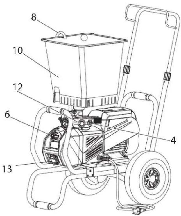
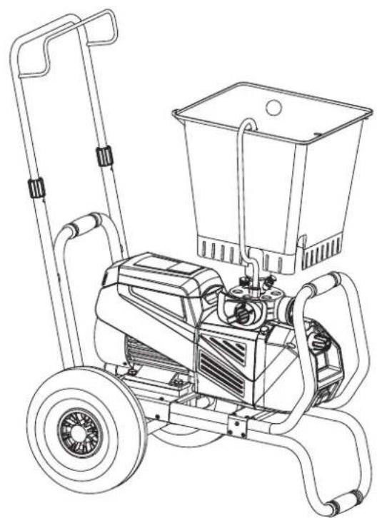
4.2 UNIT WITH UPPER HOPPER
- Ensure that the sealing surfaces of the connections are clean. Ensure that the red inlet (1) is inserted in the coating material inlet (4).
- Screw the adapter (8) onto the coating material inlet (4) and tighten until hand-tight.
- Place the hopper (9) on the adapter (8).
- Screw the union nut (5) on the return pipe (6) onto the connection (7).
4.3 HIGH PRESSURE HOSE AND SPRAY GUN
- Screw the high pressure hose (10) onto the hose connection
- Screw the spray gun (11) onto the high pressure hose
- Tighten all union nuts on high pressure hose so that no coating material can escape.
- Screw the tip holder with the selected tip onto the spray gun, align tip and tighten union nut.
4.4 CONNECTION TO THE MAINS NETWORK

Connection must always be carried out via an appropriately grounded safety outlet with residual-current-operated circuit-breaker (30 mA). An upstream circuit breaker (fuse) with 16 A (B or C characteristics) is required.
Before connecting the unit to the mains supply, ensure that the line voltage matches that specified on the unit's rating plate.
4.5 SOCKET ON UNIT
It is possible, for example, to connect an agitator, a working lamp, a curing bag etc with a maximum of 1200 Watt.

Always switch on the Super Finish 33 PLUS unit first and then the connected unit. Otherwise the fuse protection of 16 A inside the unit will react.
4.6 CLEANING PRESERVING AGENT WHEN STARTING-UP OF OPERATION INITIALLY
Unit with suction tube
Unit with hopper
- Immerse the suction system into a container filled with a suitable cleaning agent (recommendation: water).
- Fill up hopper with a suitable cleaning agent (recommendation: water).
- Set multifunction switch (1) to ⏻ (ON-circulation); the unit commences to run.
- Turn the pressure regulating knob (2) to the right until the stop is reached.
- Wait until cleaning agent is emitted from the return hose.
- Turn the pressure regulating knob (2) back approx. one rotation.
- Set multifunction switch (1) to ☑ (spray). Pressure is rising up inside the high pressure hose (visible at pressure gauge)
- Point the tip of the spray gun into an open collecting container and pull the trigger guard at the spray gun.
- The pressure is increased by turning the pressure regulating knob (2) to the right. Set approx. 10 MPa (100 bar) at the pressure gauge.
- Spray the cleaning agent out of the unit for approx. 1 - 2 min. (\~5 litres) into the open collecting container.
4.7 VENTILATE UNIT (HYDRAULIC SYSTEM) IF THE SOUND OF INLET VALVE IS NOT AUDIBLE
- Switch on the unit.
- Turn pressure regulating knob (2) three revolutions to the left.
- Set multifunction switch (1) to ☐ (ON - circulation). The hydraulic system is ventilated. Leave the unit on for two to three minutes.
- Then turn pressure regulating knob (2) to the right until stop.
- Press inlet valve pusher (4).
Sound of the inlet valve is audible.
- If not, repeat points 2 to 4 or tap gently with a small hammer on the flat of the outlet valve.
4.8 TAKING THE UNIT INTO OPERATION WITH COATING MATERIAL
Unit with suction tube
- Immerse the suction system into a container filled with coating material.
Unit with hopper
- Fill coating material into the hopper.
- Press inlet valve pusher (4) several times to release possibly clogged inlet valve
- Set multifunction switch (1) to 📋 (ON - circulation); the unit will start.
- Turn the pressure regulating knob (2) to the right until the stop is reached.
When the noise of the valves changes, the unit is bled and takes in coating material.
- If coating material exits from the return hose, turn the pressure regulating knob (2) back approx. 1 rotation.
- Set multifunction switch (1) to 📋 (spray).
Pressure is rising up inside the high pressure hose (visible at pressure gauge (3)).
- Pull of the spray gun and spray into an open collecting container in order to remove the remaining cleaning agent from the unit. When coating materials exits from the tip, close the spray gun.
- Adjust the spraying pressure by turning the pressure regulating knob (2).
- The unit is ready to spray.
5 SPRAYING TECHNOLOGY
Move the spray gun evenly during the spraying process. If this is not observed, an irregular spraying appearance will be the result. Carry out the movement with the arm, not with the wrist. A parallel distance of approx. 30 cm between the tip and the surface to be coated should always be observed. The lateral limitation of the spray fan should not to be too distinct. The edge of spraying should be gradual to facilitate overlapping of the next coat. The spray gun should always be held at an angle of 90° to the surface to be coated. A spray fan aimed obliquely at the surface to be coated leads to an unwanted spray cloud.
To achieve perfect surfaces at varnishing works, special accessories are available at Wagner, e.g. FineFinish tips or an AirCoat gun set. Your Wagner dealer will advise you.
6 HANDLING THE HIGH-PRESSURE HOSE
The unit is equipped with a high-pressure hose specially suited for diaphragm pumps.
| Danger | Danger of injury through leaking high-pressure hose. Replace any damaged high-pressure hose immediately.Never repair defective high-pressure hoses yourself! |
The high-pressure hose is to be handled with care. Avoid sharp bends and folds: the smallest bending radius is about 20 cm. Do not drive over the high-pressure hose. Protect against sharp objects and edges.
Never pull on the high-pressure hose to move the device. Make sure that the high-pressure hose cannot twist. This can be avoided by using a Wagner spray gun with a swivel joint and a hose system.
| When using the high-pressure hose while working on scaffolding, it is best to always guide the hose along the outside of the scaffolding. |
| The risk of damage rises with the age of the high-pressure hose.Wagner recommends replacing high-pressure hoses after 6 years. |
| Only use WAGNER original-high-pressure hoses with internal heating in order to ensure functionality, safety and durability. |
7 INTERRUPTION OF WORK
- Switch off unit, set multifunction switch to (pressure relief, circulation), then to 0 (OFF).
- Pull trigger guard of spray gun to decrease the pressure of the high pressure hose and the spray gun.
- Secure the spray gun, refer to the operating manual of the spray gun.
- Remove tip from tip holder and store the tip in a small vessel with suitable cleaning agent.
- Leave the suction system immersed in the coating material or immerse it in the corresponding cleaning agent. The suction filter and unit should not dry out.
- Cover the material container in order to prevent the paint from drying.

In using quick-drying or two-component coating materials, do not fail to rinse unit through with a suitable cleaning agent during the processing period.
8 CLEANING THE UNIT
A clean state is the best method of ensuring operation without problems. After you have finished spraying, clean the unit. Under no circumstances may coating material rests dry and harden in the unit. The cleaning agent used for cleaning (only with a flash point above 21 °C) must be suitable for the coating material used.

Warm water improves the cleaning effect in the case of water-dilutable coating materials.
- Secure the spray gun, refer to the operating manual of the spray gun.
Remove and clean the tip.
- Unit with suction system
- Set multifunction switch to ⬆ (ON - circulation).
- Remove suction tube from the material container, the return tube remains over the material container.
- Immerse the suction system into a container filled with a suitable cleaning agent
- Turn the pressure control valve back in order to set a minimal spraying pressure.
- Set multifunction switch to 📋 (spray).

With coating materials containing solvents, an earthed metal container must be used for cleaning into which the cleaning agent is pumped.

Caution! Do not pump or spray in container with small opening (bunghole)! See safety regulations.
- Pull the trigger guard of the spray gun in order to pump the remaining coating material from the suction hose, high-pressure hose and the spray gun into an open container (if appropriate, increase the pressure at the pressure control valve slowly in order to obtain a higher material flow).
- Set multifunction switch to ⏻ (ON - circulation).
- Pump suitable cleaning agent in the circuit for several minutes.

The cleaning effect is increased by alternatively opening and closing the spray gun.
- Set multifunction switch to 📋 (spray).
- Pump the remaining cleaning agent into an open container until the pump is empty.
- Switch off the unit
- Unit with upper hopper
- Set multifunction switch to Ⓐ (ON - circulation).
- Turn the pressure control valve back in order to set a minimal spraying pressure.
- Set multifunction switch to Ⓞ (spray).

With coating materials containing solvents, an earthed metal container must be used for cleaning into which the cleaning agent is pumped.

Caution! Do not pump or spray in container with small opening (bunghole)! See safety regulations.
- Pull the trigger guard of the spray gun in order to pump the remaining coating material from the hopper, high-pressure hose and the spray gun into an open container (if appropriate, increase the pressure at the pressure control valve slowly in order to obtain a higher material flow).
- Fill up hopper with suitable cleaning agent.
- Set multifunction switch to ⏻ (ON - circulation).
- Pump suitable cleaning agent in the circuit for several minutes.

The 20 l top container can be easily removed and emptied after cleaning.
- Set multifunction switch to Ⓧ (spray).
- Pump the remaining cleaning agent from the hopper, high-pressure hose and the spray gun into an open container.
- Set multifunction switch to ⏻ (ON - circulation).
- Switch off unit
8.1 CLEANING THE UNIT FROM THE OUTSIDE
 Danger Danger | First unplug the power plug from the outlet. Danger of short-circuits caused by water ingression! Never spray down the unit with high-pressure or high-pressure steam cleaners. |
 Danger Danger | Do not put the high-pressure hose into sol-vents. Use only a wet cloth to wipe down the outside of the hose. |
Wipe down unit externally with a cloth which has been immersed in a suitable cleaning agent.
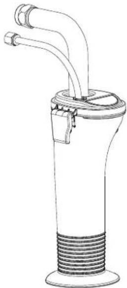
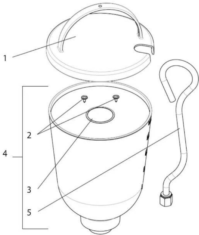
8.2 SUCTION FILTER
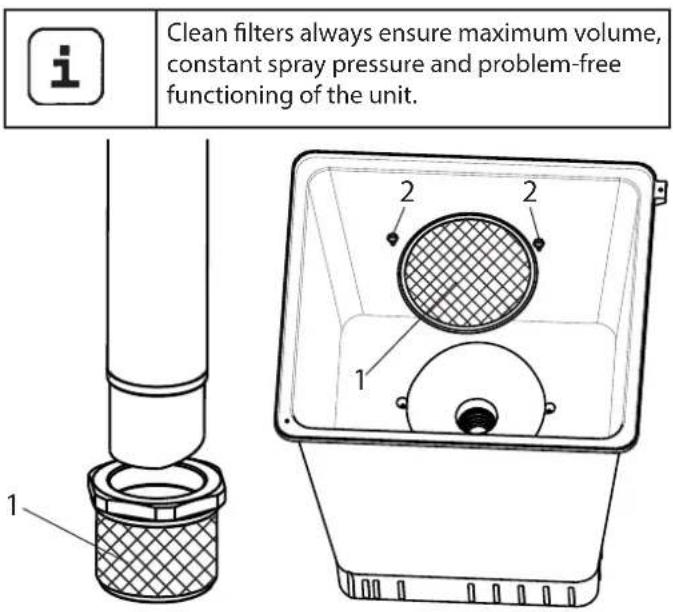
suction tube hopper
Unit with suction system
- Unscrew the filter (Item 1) from the suction tube.
- Clean or replace the filter.
Carry out cleaning with a hard brush and a corresponding cleaning agent.
Unit with hopper
- Release screws with a screwdriver (Item 2).
- Lift and remove filter disk with a screwdriver
- Clean or replace the filter disk.
Carry out cleaning with a hard brush and a corresponding cleaning agent.
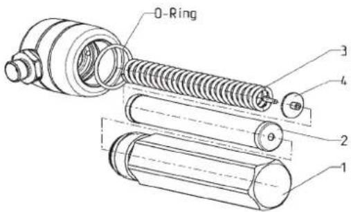
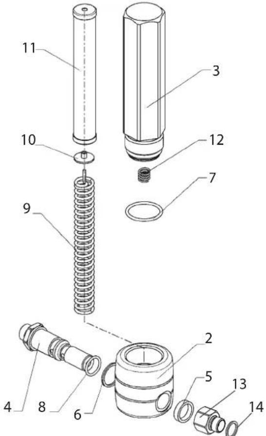
8.3 HIGH-PRESSURE FILTER
- Switch off unit - set multifunction switch to 0 (OFF).
- Open the high-pressure filter and clean the filter insert. To do so:
- Unscrew the filter housing (1) by hand.
- Remove the filter insert (2) and pull out the bearing spring (3).
- Clean all the parts with the corresponding cleaning agent. If compressed air is available – blow through the filter insert and bearing spring.
- When mounting the filter ensure that the bearing ring (4) in the filter insert is positioned correctly and check the O-ring at the filter housing for damage.
- Screw on the filter housing by hand until it stops (a higher tightening force only impedes later dismantling).
8.4 CLEANING THE AIRLESS SPRAY GUN
- Rinse the Airless spray gun with a suitable cleaning agent under lower operating pressure.
- Clean the tip thoroughly with a suitable cleaning agent so that no suitable coating material rests remain.
- Do not store the tip in solvent because this reduces the durability considerably.
- Clean the outside of the Airless spray gun thoroughly.
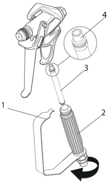
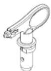
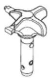
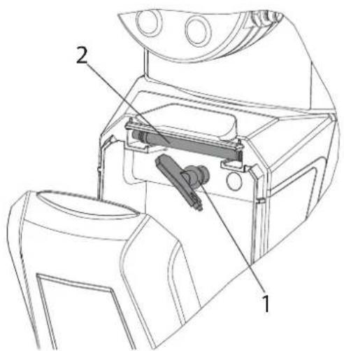
Insertion filter in the Airless spray gun
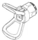
- Unclip the top of the trigger guard (1) from the gun head.
- Using the bottom of the trigger guard as a wrench, loosen and remove the handle assembly (2) from the gun head.
- Pull the old filter (3) out of the gun head. Clean or replace.
- Slide the new filter, tapered end (4) first, into the gun head.
- Screw the handle grip back into the spray gun head and tighten with the integrated spanner.
- Snap the trigger guard back onto the gun head.
9 SERVICING
9.1 GENERAL SERVICING
 | We strongly recommend having an annual check carried out by technicians for safety reasons. Please observe all the applicable national regulations. |
 | You can servicing of the unit carried out by the Wagner Service. Favourable conditions can be agreed with a service agreement and/or maintenance packages. |
Minimum check before every startup:
- Check the high-pressure hose, spray gun with rotary joint, power supply cable with plug for damage.
- Check whether the pressure gauge can be read.
Check at periodical intervals:
- Check inlet and outlet valve according wear. Clean it and replace worn out parts.
- Check all filter inserts (spray gun, suction system) clean it and replace if necessary.
9.2 HIGH-PRESSURE HOSE
Inspect the high-pressure hose visually for any notches or bulges, in particular at the transition in the fittings. It must be possible to turn the union nuts freely. A conductivity of less than
1 MΩ must exist across the entire length.
 Attention Attention | Have all the electric tests carried by the Wagner Service. |
 | The risk of damage rises with the age of the high-pressure hose.Wagner recommends replacing high-pressure hoses after 6 years. |
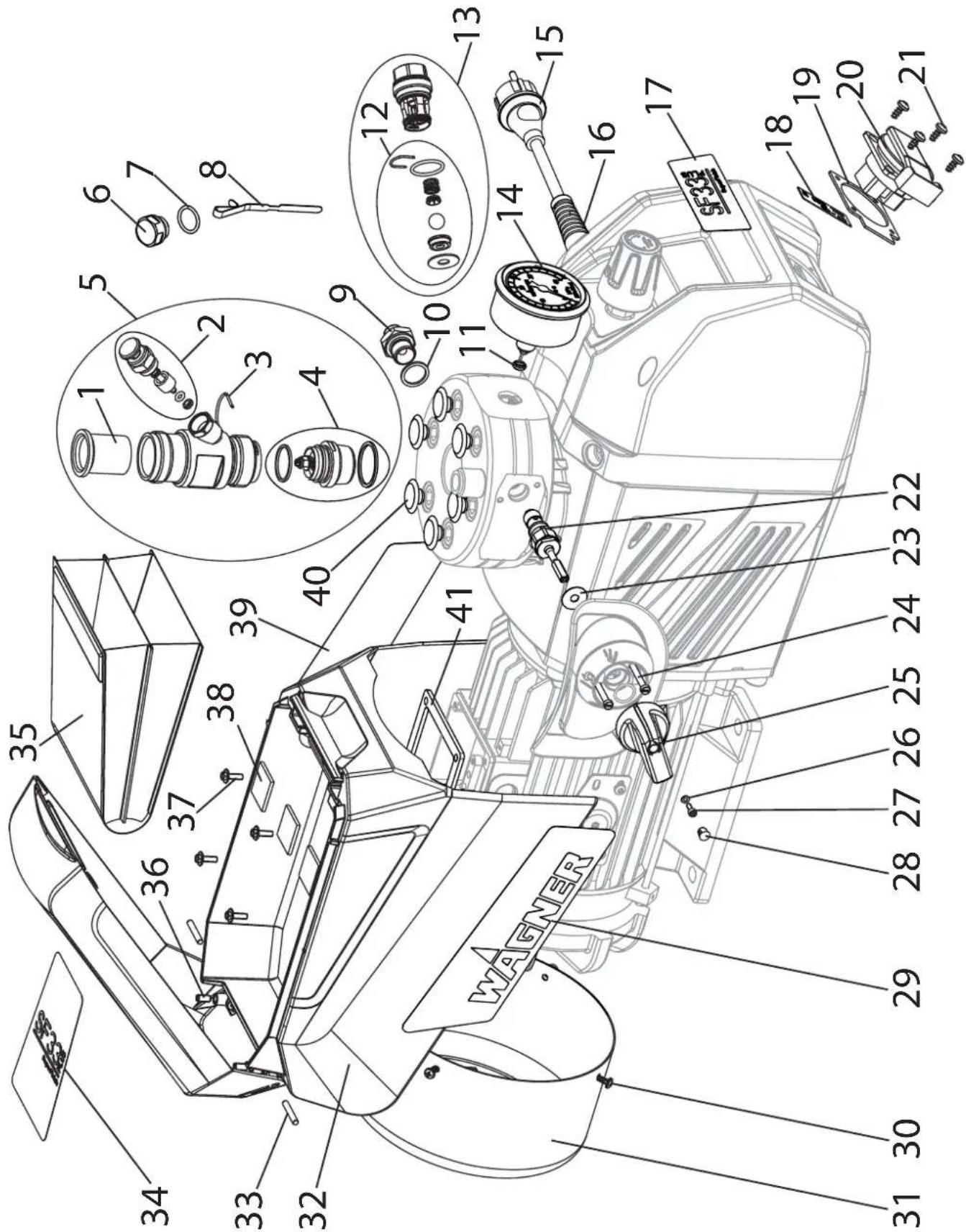
10 REPAIRS AT THE UNIT

Switch the unit off. Before all repair work: Unplug the power plug from the outlet.
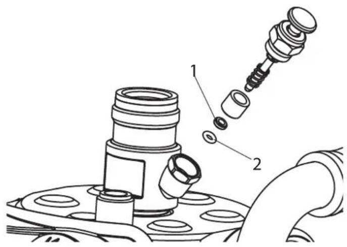
10.1 INLET VALVE PUSHER
- Use a 17 mm spanner to screw out the inlet valve button.
- Replace the wiper (1) and O-ring (2).
10.2 INLET VALVE
- Place the enclosed 30 mm wrench on the trigger housing (1).
- Loosen the trigger housing (1) with light blows of a hammer on the end of the wrench.
- Screw out the trigger housing with the inlet valve (2) from the paint section.
- Pull of the clasp (3) using the enclosed screwdriver.
- Place the enclosed 30 mm wrench on the inlet valve (2). Turn out the inlet valve carefully.
- Clean the valve seat (4) with a cleaning agent and brush (ensure that no brush hairs are left behind).
- Clean the seals (5, 6) and check for damage. Replace, if necessary.
- Check all the valve parts for damage. In case of visible wear replace the inlet valve.
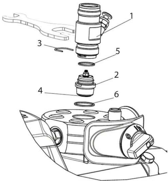
Installation
- Insert the inlet valve (2) into the trigger housing (1) and secure with the clasp (3). Ensure that the (black) seal (5) is mounted in the trigger housing.
- Screw the unit from the trigger housing and the inlet valve into the paint section. The same (black) seal (6) has to be mounted in the paint section.
- Tighten the trigger housing with the 30 mm wrench and tighten with three light blows of the hammer on the end of the wrench. (Corresponds to approx. 90 Nm tightening torque).
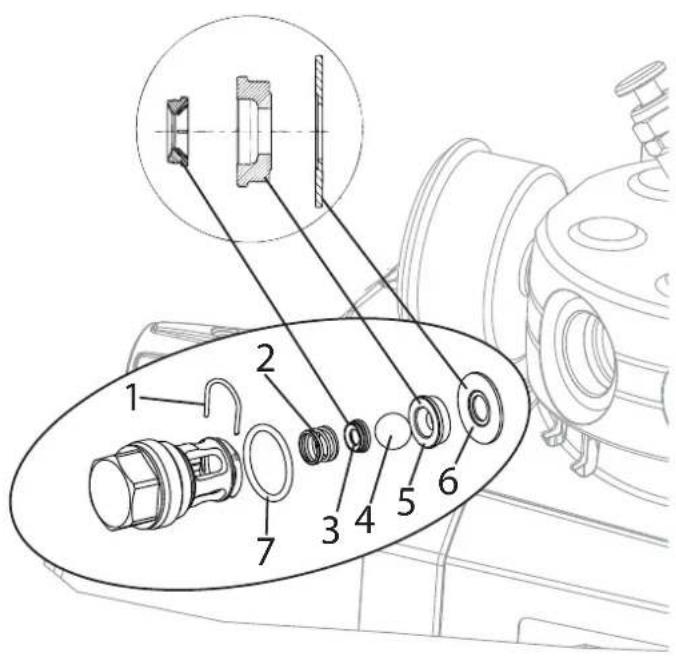
10.3 OUTLET VALVE
- Use a 22 mm wrench to screw the outlet valve from the paint section.
- Carefully pull of the clasp (1) using the enclosed screw-driver. The compression spring (2) presses ball (4) and valve seat (5) out.
- Clean or replace the components.
- Check the O-ring (7) for damage.
- Check the installation position when mounting the spring support ring (3) (clipped onto spring (2)), outlet valve seat (5) and seal (6), refer to figure.
The torque for fitting the outlet valve is 50 Nm.
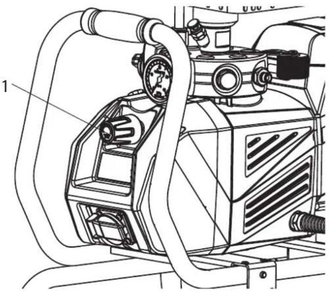
10.4 PRESSURE CONTROL VALVE
| Danger | Only have the pressure control valve (1) replaced by the customer service.The max. operating pressure has to be reset by the customer service. |
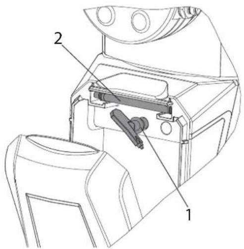
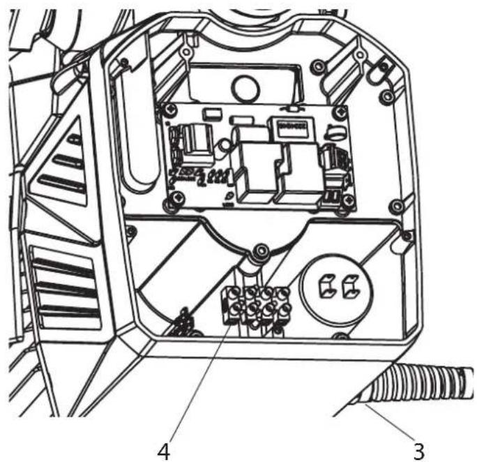
10.5 REPLACING THE POWER CABLE
 | This may only be carried out by a skilled electrician. No liability is assumed for incorrect installation.Switch the unit off.Before all repair work: Unplug the power plug from the outlet. |
 | Do not dismantle the sealed pressure control valve (1) so as to ensure that the pressure setting is retained. |
 | To remove the pump, move it to an upright position. Open the oil lock screw (5) to release any excess pressure that has built up in the hydraulic oil housing. |
- Completely unscrew the pressure control valve (1) (spanner width 17 mm).
- Remove the front cover (2) by loosening the 5 screws using an Allen key (SW 3).
- Loosen the cable threaded joint (3).
- Loosen the wires in the mains terminal (4).
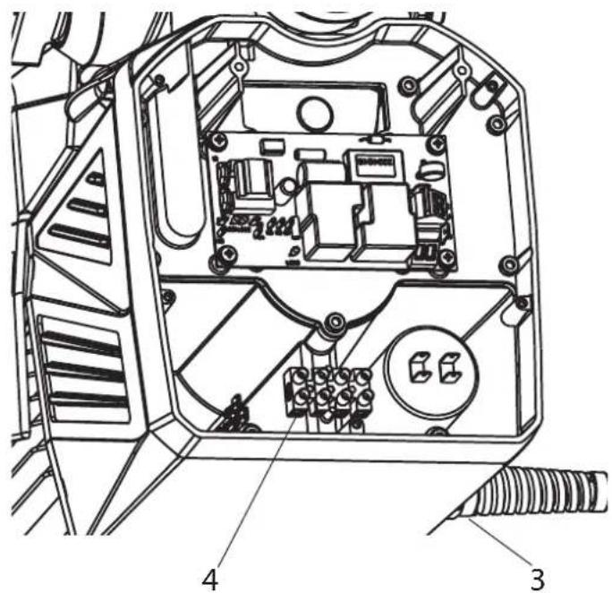
- Replace the unit connecting line.
- Completely unscrew the pressure control valve (1) (spanner width 17 mm).
- Remove the front cover (2) by loosening the 5 screws using an Allen key (SW 3).
- Loosen the cable threaded joint (3).
- Loosen the wires in the mains terminal (4).
- Replace the unit connecting line.
(only an approved power cable with the designation H07-RNF with a splash-proof plug may be used). - Connect the green/yellow wire to the contact with the PE sign.
- Remount the covers carefully (do not squeeze any cables!)
- Replace the pressure control valve in the housing and screw into position.
10.6 TYPICAL WEAR PARTS
Despite the use of high-quality materials the highly abrasive effect of the paints means that wear can occur at the following parts:
Inlet valve (spare part Order No.: 0341247)
For replacing refer to Section 10.2
(failure becomes noticeable through performance loss and/or poor or no suction)
Outlet valve (spare part Order No.: 0341702)
For replacing refer to Section 10.3
(failure becomes noticeable through performance loss and/or poor suction) The outlet valve is usually considerably more durable than the inlet valve. Thorough cleaning may already help here.
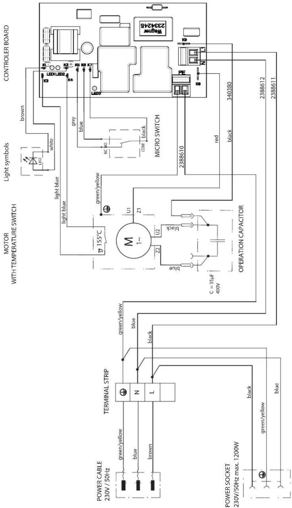
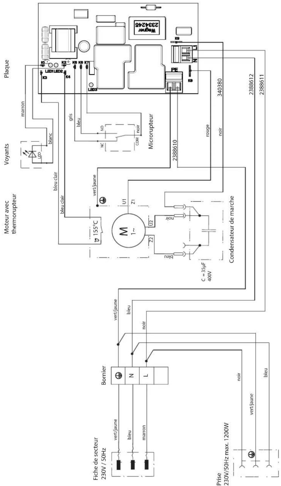
10.7 CONNECTION DIAGRAM
10.8 REMEDY IN CASE OF FAULTS
| TYPE OF MALFUNCTION POSSIBLE CAUSE MEASURE FOR ELIMINATION OF MALFUNCTION | ||
| Unit does not start (green symbols on the switch do not light up) | No voltageThe device fuse has tripped due to overloadMulti-function switch not set back previously to „0” | Check voltage supplySwitch off the device and allow the motor to cool down for a few minutes until the green symbols light up again. Switch device on again.Set multi-function switch to „0” and then switch back on |
| Unit does not suck in | Inlet valve cloggedInlet valve trigger leaks, sucks in ancillary air.Inlet/outlet valve soiled / wornA foreign body (e.g. paint residue) has been sucked inUnit with suction system:Filter extends beyond the liquid level and sucks in air.Suction filter cloggedSuction pipe not tightened, i.e. the unit sucks in ancillary air.Device with upper hopper:Filter disk cloggedAir in the hydraulic systemToo little oil (check with an oil dipstick) | Press the inlet valve button until the stop is reached several times by handReplace stripper and o-ring, refer to section 10.1.Remove the valves and clean then (-> refer to section 10.2/10.3) / replace worn partsRefill coating materialClean or replace suction filter.Clean and tighten connections.Clean or replace filter disk.Release air from unit (hydraulic system), i.e. turn pressure regulating valve three revolutions to theleft(possibly pull gently on the rotary knob). Allow the unit to run one or two minutes. After that, turn pressure regulating valve to therightto set the desired operating pressure.Top up the oil and contact Wagner Service to search for the leak |
| Unit has sucked in and generates pressure but the pressure collapses when the trigger is pulled. | No tip mounted in the spray gunTip too largeSuction filter cloggedSpecially for unit with suction system:Suction system not tightOutlet valve parts wornPaint too viscousPaint contains particles / small stonesRelief valve defective | Mount tipUse a smaller tipClean suction filter or replace.Clean and tighten connection points.Replace outlet valve parts, refer to section 10.3.Dilute the paintPlease contact Wager Customer ServicePlease contact Wager Customer Service |
| Unit reached pressure, but the pressure collapses during spraying. pressure gauge still shows high pressure. | Clogged filter do not let enough paint passGun filter insert fitted the wrong way roundTip clogged | Check/clean the (high-pressure filter) gun filterFit the gun filter insert correctly (refer to section 8.4)Clean the tip |
| Hard pressure jolts and excessive vibration on the spray gun and unit | High-pressure hose for diaphragm unit not suitableOutlet valve parts worn | Use original WAGNER high-pressure hose.Replace outlet valve parts, refer to section 10.3. |
11 SPARE PARTS AND ACCESSORIES
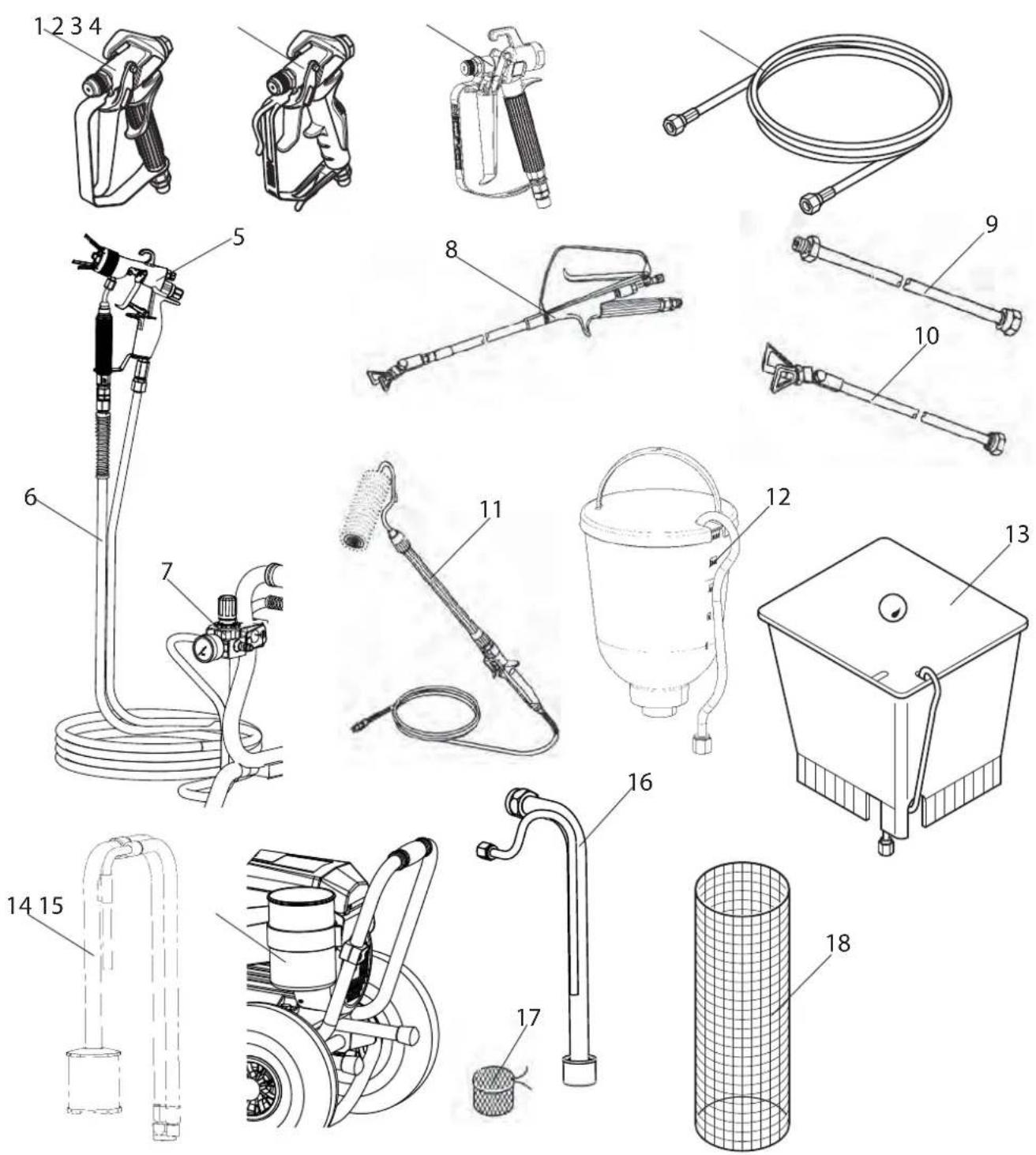
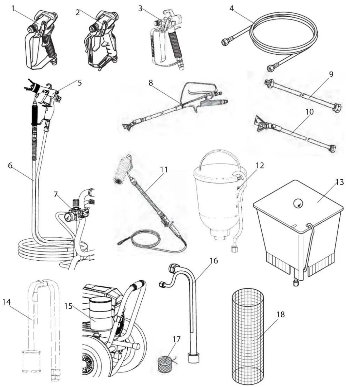
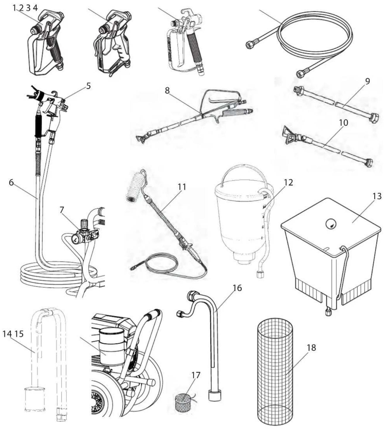
11.1 SUPER FINISH 33 PLUS ACCESSORIES
| ITEM | DESIGNATION ORDER NO. | |
| 1 Spray | gun Vector Pro(2-finger, G thread 7/8")Spray gun Vector Pro(4-finger, G thread 7/8") | 0538 0410538 040 |
| 2 Spray | gun Vector Grip (2-finger and 4-finger, G thread 7/8") | 0538 043 |
| 3 Spray | gun AG-14 (stainless steel, F thread 11/16") | 0502 166 |
| 4 HP | hose DN-3, 7.5mHP hose DN 6 mm, 15 mHP hose DN 6 mm, 30 m | 9984 5839984 5079984 562 |
| 5 | AirCoat spray gun AC 4500 (blue) 2368 269 | |
| 6 Double hose 9984 564 | ||
| 7 AirCoat-controller set 0340 250 | ||
| 8 | Pole gunLength 120 cm; G thread 7/8"Length 200 cm; G thread 7/8" | 0296 4410296 442 |
| 9 | Tip extension (G thread 7/8")Length 15 cmLength 30 cmLength 45 cmLength 60 cm | 0556 0740556 0750556 0760556 077 |
| 10 Tip | extension with slewable knee joint(F thread 11/16")Length 100 cmLength 200 cmLength 300 cm | 0096 0150096 0160096 017 |
| Adapter 11/16" - 7/8" 0555 300 | ||
| 11 Inline Roller 0345 010 | ||
| 12 Hopper 5l 0341 265 | ||
| 13 Hopper 20l 0341 266 | ||
| 14 Suction system (flexible) for dispersions 0034 630 | ||
| 15 Cleaning container for suction systemwith holder (only for flexible suctionsystem) | 2343 481 | |
| 16 Suction system (rigid) for dispersions 2342879 | ||
| 17 Filter bag, mesh width 0,3 mm 0097 531 | ||
| 18 | Metex-ReuseReuse for pre-filtering of coating material in vessel. Place suction pipe in thereuse.Sieve package (5 pcs) for paintSieve package (5 pcs) for dispersion | 0034 9500034 9520034 951 |
RECOMMENDATION
PumpRunner for rigid suction systems (order No. 2306987, suction system not included)
Universal accessories for cleaning, clean transportation and preservation of the pump unit.
Features:
- Simpler cleaning – the cleaning liquid circulates constantly through the pump making thorough cleaning of the interior
- No cleaning necessary during work stoppage or change of location because the paint in the pump cannot dry out or leak
- Better protection
- Simple assembly
RECOMMENDATION
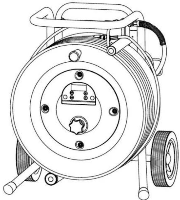
Hose reel HR30
(order No. 2306987, without high-pressure hose)
Smart hose management for more convenient working and transport. Suitable for max. 30 m of hose (1/4 NPSM). Individual hoses can be connected using adapter 34038.
TEMPSPRAY
The paint material is heated to the required temperature uniformly by an electric heating element, which is located inside the hose (regulated from 20°C to 60°C).
Advantages:
- Constant paint temperature even at low outside temperatures
- Considerably better working of high viscosity coating materials
• Increased application efficiency
• Savings in solvents due to reduction in viscosity
• Adaptable to all airless units
| Order No. Description | |
| 23116592311852 | TempSpray H 126 (ideal for lacquer jobs)Basic unit 1/4" incl. stainless steel hose, DN6, 1/4", 10mSpraypack consisting of: basic unit (2311659), Airless gun Vector Grip G thread, incl. Trade Tip 3 nozzle holder and 2SpeedTip L10 (208/510) |
| 23116602311853 | TempSpray H 226 (ideal for dispersions/materials with high viscosity)Basic unit 1/4" incl. Hose reel, heated hose DN10, 15m, hose 1/4" DN4, 1mSpraypack consisting of: Basic unit (2311660), Airless un AG 14 G thread, incl. Trade Tip 3 nozzle holder and 2SpeedTip D10 (111/419) |
| 23116612311854 | TempSpray H 326 (ideal for dispersions/materials with high viscosity)Basic unit 1/4" incl. Hose reel, heated hose DN10, 30m, hose 1/4" DN4, 1mSpraypack consisting of: Basic unit (2311661), Airless un AG 14 G thread, incl. Trade Tip 2 nozzle holder and 2SpeedTip D20 (115/421) |
TempSpray H 126
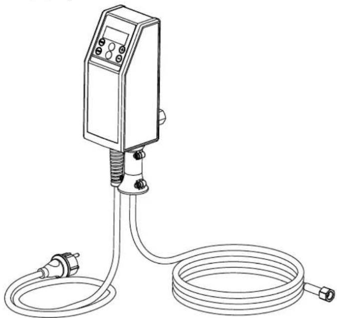
TempSpray H 226 / H 326

HEA NOZZLES FOR LOW-MIST SPRAYING AT LOW PRESSURE

HEA stands for High Efficiency Airless, an innovative nozzle technology revolutionising airless spraying. HEA nozzles allow the pressure of the spray device to be reduced right down and allow it to work in the low-pressure range (ideally at 80 - 140 bar). The nozzles can be used with all TradeTip 3 nozzle holders and WAGNER devices.
Some paints may need to be diluted to achieve the best result possible. The experts at Wagner application technology have therefore tested a wide range of materials for you. Their recommendations can be found in the Wagner Spray Guide at sprayguide. wagner-group.com.

Set the low pressure in the HEA range and start.
Even spray pattern without spray edges.
If edges are visible, slowly increase the pressure.
HEA tip table

All of the tips in the table below are supplied together with the appropriate gun filter.
| Application Tip marking Spray | angle | Bore inch / mm | Spraying width mm 1) | Gun fi Iter Order no. | ||
| Synthetic-resin paints | 211 | 20 ° | 0.011 / 0.28 | 120 | red | 0554211 |
| PVC paints | 311 | 30 ° | 0.011 / 0.28 | 150 | red | 0554311 |
| 411 | 40 ° | 0.011 / 0.28 | 190 | Rot | 0554411 | |
| Paints, primers | 213 | 20 ° | 0.013 / 0.33 | 120 | red | 0554213 |
| Fillers | 313 | 30 ° | 0.013 / 0.33 | 150 | red | 0554313 |
| 413 | 40 ° | 0.013 / 0.33 | 190 | red | 0554413 | |
| Fillers | 415 | 40 ° | 0.015 / 0.38 | 190 | yellow | 0554415 |
| Rust protection paints | 515 | 50 ° | 0.015 / 0.38 | 225 | yellow | 0554515 |
| 615 | 60 ° | 0.015 / 0.38 | 270 | yellow | 0554615 | |
| Rust protection paints | 417 | 40 ° | 0.017 / 0.43 | 190 | white | 0554417 |
| Latex paints | 517 | 50 ° | 0.017 / 0.43 | 225 | white | 0554517 |
| Dispersions | 617 | 60 ° | 0.017 / 0.43 | 270 | white | 0554617 |
| Rust protection paints | 519 | 50 ° | 0.019 / 0.48 | 225 | white | 0554519 |
| Latex paints | 619 | 60 ° | 0.019 / 0.48 | 270 | white | 0554619 |
| Dispersions | ||||||
| Flame retardant 421 | 40 ° | 0.021 / 0.53 | 190 | white | 0554421 | |
| 521 | 50 ° | 0.021 / 0.53 | 225 | white | 0554521 | |
| 621 | 60 ° | 0.021 / 0.53 | 270 | white | 0554621 | |
1) Spray width at about 30 cm to the object and 100 bar (10 MPa) pressure with synthetic-resin paint 20 DIN seconds.
Airless tip table
Wagner
TradeTip 3 tip
up to 270 bar
(27 MPa)
without tip
G thread (7/8 - 14 UN)
Order no.0289390
without tip
F thread (11/16 - 16 UN)
Order no. 0289391

All of the tips in the table below are supplied together with the appropriate gun filter.
| Application Tip marking Spray | angle | Bore inch / mm | Spraying width mm 1) | Gun fi Iter Order no. | ||
| Water-thinnable and solvent-based paints and varnishes, oils, separating agents | 107 | 10° | 0.007/0.18 | 100 | red | 0553107 |
| 207 | 20° | 0.007/0.18 | 120 | red | 0553207 | |
| 307 | 30° | 0.007/0.18 | 150 | red | 0553307 | |
| 407 | 40° | 0.007/0.18 | 190 | red | 0553407 | |
| 109 | 10° | 0.009/0.23 | 100 | red | 0553109 | |
| 209 | 20° | 0.009/0.23 | 120 | red | 0553209 | |
| 309 | 30° | 0.009/0.23 | 150 | red | 0553309 | |
| 409 | 40° | 0.009/0.23 | 190 | red | 0553409 | |
| 509 | 50° | 0.009/0.23 | 225 | red | 0553509 | |
| 609 | 60° | 0.009/0.23 | 270 | red | 0553609 | |
| Synthetic-resin paintsPVC paints | 111 | 10° | 0.011/0.28 | 100 | red | 0553111 |
| 211 | 20° | 0.011/0.28 | 120 | red | 0553211 | |
| 311 | 30° | 0.011/0.28 | 150 | red | 0553311 | |
| 411 | 40° | 0.011/0.28 | 190 | red | 0553411 | |
| 511 | 50° | 0.011/0.28 | 225 | red | 0553511 | |
| 611 | 60° | 0.011/0.28 | 270 | red | 0553611 | |
| Paints, primersFillers | 113 | 10° | 0.013/0.33 | 100 | red | 0553113 |
| 213 | 20° | 0.013/0.33 | 120 | red | 0553213 | |
| 313 | 30° | 0.013/0.33 | 150 | red | 0553313 | |
| 413 | 40° | 0.013/0.33 | 190 | red | 0553413 | |
| 513 | 50° | 0.013/0.33 | 225 | red | 0553513 | |
| 613 | 60° | 0.013/0.33 | 270 | red | 0553613 | |
| 813 | 80° | 0.013/0.33 | 330 | red | 0553813 | |
| FillersRust protection paints | 115 | 10° | 0.015/0.38 | 100 | yellow | 0553115 |
| 215 | 20° | 0.015/0.38 | 120 | yellow | 0553215 | |
| 315 | 30° | 0.015/0.38 | 150 | yellow | 0553315 | |
| 415 | 40° | 0.015/0.38 | 190 | yellow | 0553415 | |
| 515 | 50° | 0.015/0.38 | 225 | yellow | 0553515 | |
| 615 | 60° | 0.015/0.38 | 270 | yellow | 0553615 | |
| 715 | 70° | 0.015/0.38 | 300 | yellow | 0553715 | |
| 815 | 80° | 0.015/0.38 | 330 | yellow | 0553815 | |
| Rust protection paintsLatex paintsDispersions | 117 | 10° | 0.017/0.43 | 100 | white | 0553117 |
| 217 | 20° | 0.017/0.43 | 120 | white | 0553217 | |
| 317 | 30° | 0.017/0.43 | 150 | white | 0553317 | |
| 417 | 40° | 0.017/0.43 | 190 | white | 0553417 | |
| 517 | 50° | 0.017/0.43 | 225 | white | 0553517 | |
| 617 | 60° | 0.017/0.43 | 270 | white | 0553617 | |
| 717 | 70° | 0.017/0.43 | 300 | white | 0553717 | |
| 817 | 80° | 0.017/0.43 | 330 | white | 0553817 | |
| Rust protection paintsLatex paintsDispersions | 219 | 20° | 0.019/0.48 | 120 | white | 0553219 |
| 319 | 30° | 0.019/0.48 | 150 | white | 0553319 | |
| 419 | 40° | 0.019/0.48 | 190 | white | 0553419 | |
| 519 | 50° | 0.019/0.48 | 225 | white | 0553519 | |
| 619 | 60° | 0.019/0.48 | 270 | white | 0553619 | |
| 719 | 70° | 0.019/0.48 | 300 | white | 0553719 | |
| 819 | 80° | 0.019/0.48 | 330 | white | 0553819 | |
| 919 | 90° | 0.019/0.48 | 385 | white | 0553919 | |
| Flame retardant 221 | 20° | 0.021/0.53 | 120 | white | 0553221 | |
| 321 | 30° | 0.021/0.53 | 150 | white | 0553321 | |
| 421 | 40° | 0.021/0.53 | 190 | white | 0553421 | |
| 521 | 50° | 0.021/0.53 | 225 | white | 0553521 | |
| 621 | 60° | 0.021/0.53 | 270 | white | 0553621 | |
| 721 | 70° | 0.021/0.53 | 300 | white | 0553721 | |
| 821 | 80° | 0.021/0.53 | 330 | white | 0553821 | |

All of the tips in the table below are supplied together with the appropriate gun filter.
| Application Tip marking Spray | angle | Bore inch / mm | Spraying width mm 1) | Gun fi Iter Order no. | ||
| Roof coatings 223 | 20° | 0.023 / 0.58 | 120 | white | 0553223 | |
| 323 | 30° | 0.023 / 0.58 | 150 | white | 0553323 | |
| 423 | 40° | 0.023 / 0.58 | 190 | white | 0553423 | |
| 523 | 50° | 0.023 / 0.58 | 225 | white | 0553523 | |
| 623 | 60° | 0.023 / 0.58 | 270 | white | 0553623 | |
| 723 | 70° | 0.023 / 0.58 | 300 | white | 0553723 | |
| 823 | 80° | 0.023 / 0.58 | 330 | white | 0553823 | |
| Thick-fi Im materials,Corrosion protectionSpray fi ller | 225 | 20° | 0.025 / 0.64 | 120 | white | 0553225 |
| 325 | 30° | 0.025 / 0.64 | 150 | white | 0553325 | |
| 425 | 40° | 0.025 / 0.64 | 190 | white | 0553425 | |
| 525 | 50° | 0.025 / 0.64 | 225 | white | 0553525 | |
| 625 | 60° | 0.025 / 0.64 | 270 | white | 0553625 | |
| 725 | 70° | 0.025 / 0.64 | 300 | white | 0553725 | |
| 825 | 80° | 0.025 / 0.64 | 330 | white | 0553825 | |
| 227 | 20° | 0.027 / 0.69 | 120 | white | 0553227 | |
| 327 | 30° | 0.027 / 0.69 | 150 | white | 0553327 | |
| 427 | 40° | 0.027 / 0.69 | 190 | white | 0553427 | |
| 527 | 50° | 0.027 / 0.69 | 225 | white | 0553527 | |
| 627 | 60° | 0.027 / 0.69 | 270 | white | 0553627 | |
| 827 | 80° | 0.027 / 0.69 | 330 | white | 0553827 | |
| 229 | 20° | 0.029 / 0.75 | 120 | white | 0553229 | |
| 329 | 30° | 0.029 / 0.75 | 150 | white | 0553329 | |
| 429 | 40° | 0.029 / 0.75 | 190 | white | 0553429 | |
| 529 | 50° | 0.029 / 0.75 | 225 | white | 0553529 | |
| 629 | 60° | 0.029 / 0.75 | 270 | white | 0553629 | |
| 231 | 20° | 0.031 / 0.79 | 120 | white | 0553231 | |
| 331 | 30° | 0.031 / 0.79 | 150 | white | 0553331 | |
| 431 | 40° | 0.031 / 0.79 | 190 | white | 0553431 | |
| 531 | 50° | 0.031 / 0.79 | 225 | white | 0553531 | |
| 631 | 60° | 0.031 / 0.79 | 270 | white | 0553631 | |
| 731 | 70° | 0.031 / 0.79 | 300 | white | 0553731 | |
| 831 | 80° | 0.031 / 0.79 | 330 | white | 0553831 | |
| 233 | 20° | 0.033 / 0.83 | 120 | white | 0553233 | |
| 333 | 30° | 0.033 / 0.83 | 150 | white | 0553333 | |
| 433 | 40° | 0.033 / 0.83 | 190 | white | 0553433 | |
| 533 | 50° | 0.033 / 0.83 | 225 | white | 0553533 | |
| 633 | 60° | 0.033 / 0.83 | 270 | white | 0553633 | |
| 235 | 20° | 0.035 / 0.90 | 120 | white | 0553235 | |
| 335 | 30° | 0.035 / 0.90 | 150 | white | 0553335 | |
| 435 | 40° | 0.035 / 0.90 | 190 | white | 0553435 | |
| 535 | 50° | 0.035 / 0.90 | 225 | white | 0553535 | |
| 635 | 60° | 0.035 / 0.90 | 270 | white | 0553635 | |
| 735 | 70° | 0.035 / 0.90 | 300 | white | 0553735 | |
| 439 | 40° | 0.039 / 0.99 | 190 | white | 0553439 | |
| 539 | 50° | 0.039 / 0.99 | 225 | white | 0553539 | |
| 639 | 60° | 0.039 / 0.99 | 270 | white | 0553639 | |
| Heavy duty applications | 243 | 20° | 0.043 / 1.10 | 120 | green | 0553243 |
| 443 | 40° | 0.043 / 1.10 | 190 | green | 0553443 | |
| 543 | 50° | 0.043 / 1.10 | 225 | green | 0553543 | |
| 643 | 60° | 0.043 / 1.10 | 270 | green | 0553643 | |
| 445 | 40° | 0.045 / 1.14 | 190 | green | 0553445 | |
| 545 | 50° | 0.045 / 1.14 | 225 | green | 0553545 | |
| 645 | 60° | 0.045 / 1.14 | 270 | green | 0553645 | |
| 451 | 40° | 0.051 / 1.30 | 190 | green | 0553451 | |
| 551 | 50° | 0.051 / 1.30 | 225 | green | 0553551 | |
| 651 | 60° | 0.051 / 1.30 | 270 | green | 0553651 | |
| 252 | 20° | 0.052 / 1.32 | 120 | green | 0553252 | |
| 455 | 40° | 0.055 / 1.40 | 190 | green | 0553455 | |
| 555 | 50° | 0.055 / 1.40 | 225 | green | 0553555 | |
| 655 | 60° | 0.055 / 1.40 | 270 | green | 0553655 | |
| 261 | 20° | 0.061 / 1.55 | 120 | green | 0553261 | |
| 461 | 40° | 0.061 / 1.55 | 190 | green | 0553461 | |
| 561 | 50° | 0.061 / 1.55 | 225 | green | 0553561 | |
| 661 | 60° | 0.061 / 1.55 | 270 | green | 0553661 | |
| 263 | 20° | 0.063 / 1.60 | 120 | green | 0553263 | |
| 463 | 40° | 0.063 / 1.60 | 190 | green | 0553463 | |
| 565 | 50° | 0.065 / 1.65 | 225 | green | 0553565 | |
| 665 | 60° | 0.065 / 1.65 | 270 | green | 0553665 | |
| 267 | 20° | 0.067 / 1.70 | 120 | green | 0553267 | |
| 467 | 40° | 0.067 / 1.70 | 190 | green | 0553467 |
1) Spray width at about 30 cm to the object and 100 bar (10 MPa) pressure with synthetic-resin paint 20 DIN seconds.
2SpeedTip
The innovative changeover nozzle from WAGNER combines two nozzle cores into one nozzle.
2 Speed Tip holder Order no. 0271065
Tip table
| Object size Painting material | |||
| Lacquer (L) Emulsion (D) Filler (S) | |||
| Small | D5Nozzles: 111 / 415Order no. 0271 062 | S5Nozzles: 225 / 629Order no. 0271 064 | |
| D7Nozzles: 113 / 417Order no. 0271 063 | |||
| L10Nozzles: 208 / 510Order no. 0271 042 | D10Nozzles: 111 / 419Order no. 0271 045 | S10Nozzles: 527 / 235Order no. 0271 049 | |
| Medium | L20Nozzles: 210 / 512Order no. 0271 043 | D20Nozzles: 115 / 421Order no. 0271 046 | S20Nozzles: 539 / 243Order no. 0271 050 |
| Large | L30Nozzles: 212 / 514Order no. 0271 044 | D30Nozzles: 115 / 423Order no. 0271 047 | S30Nozzles: 543 / 252Order no. 0271 051 |
| X-Large | D40Nozzles: 117 / 427Order no. 0271 048 | ||
| Recommended gun fi Iter red white - | |||
11.2 SPARE PARTS LIST SF 33 PLUS
| ITEM | ORDER-NO DESIGNATION |
| 1 0340 | 339 Inlet |
| 2 0341 | 241 Inlet valve trigger |
| 3 0341 | 336 Clasp |
| 4 0341 | 247 Inlet valve complete |
| 5 0341 | 255 Inlet valve housing compl. |
| 6 0341 | 349 Oil cap screw |
| 7 9971 | 146 O-ring |
| 8 2370 | 128 Oil measuring stick |
| 9 0344 | 337 Double socket |
| 10 9970 | 103 Sealing ring |
| 11 9970 | 109 Sealing ring |
| 12 0341 | 702 Outlet valve, service set |
| 13 0341 | 246 Outlet valve complete |
| 14 2383 | 994 Pressure gauge |
| 15 0261 | 352 Mains cableH07-RNF 3 × 1.5mm2 , 6m long |
| 16 2402 | 675 Cable threaded joint |
| 17 2386 | 856 Label SF 33 PLUS |
| 18 2388 | 995 Warning notice |
| 19 9950 | 242 Seal |
| 20 9950 | 241 Socket |
| 21 9905 | 113 Oval head screw 5x10 |
| 22 2384 | 484 Relief valve compl. |
| 23 0341 | 414 Washer |
| 24 2334 | 205 Cylinder screw with hex socket |
| 25 2384 | 478 Rotary knob |
| 26 9920 | 207 Washer |
| 27 9906 | 029 Cylinder screw with hex socket |
| 28 9990 | 864 Cover cap |
| 29 2386 | 858 Label (right) |
| 30 9902 | 225 Oval head screw 3.5 × 9.5 |
| 31 2392 | 781 Fan cover |
| 32 2383 | 937 Tool box with lid compl. (incl. items 33, 36, 41) |
| 33 9930 | 114 Cylindrical pin |
| ITEM | ORDER-NO DESIGNATION |
| 34 2386 | 857 Label SF 33 PLUS |
| 35 2384 | 739 Internal compartment, tool box |
| 36 9901 | 105 Threaded pin |
| 37 9900 | 248 Hexagon bolt with flange |
| 38 9995 | 234 Pressure cap |
| 39 2386 | 859 Label (left) |
| 40 9990 | 535 Protection cap |
| 41 2344 | 692 Motor gasket |
Spare parts diagram SF 33 PLUS
11.3 SPARE PARTS LIST HIGH-PRESSURE FILTER
| ITEM | ORDER NO. DESIGNATION | |
| 1 | 2399 | 672 High-pressure filter HF-01 compl. |
| 2 | 0097 | 301 Filter block |
| 3 | 0097 | 302 Filter housing |
| 4 | 0097 | 306 Hollow screw |
| 5 | 0097 | 304 Seal ring |
| 6 | 9970 | 110 Seal ring |
| 7 | 9974 | 027 O-ring 30x2 (PTFE) |
| 8 | 9971 | 401 O-ring 16x2 (PTFE) |
| 9 | 0508 | 749 Bearing spring |
| 10 | 0508 | 603 Bearing ring |
| 11 | 0508 748Filter insert 60 meshesOptional:0508 450Filter insert 100 meshes0508 449Filter insert 30 meshes | |
| 12 | 9994 | 245 Pressure spring |
| 13 | 2399 | 670 Screw-in connector |
| 14 | 9970 | 103 Sealing ring |
Spare parts diagram high-pressure filter
Spare parts diagram trolley
11.5 SPARE PARTS LIST SUCTION SYSTEM
| ITEM ORDER NO. DESIGNATION | |
| 1 2370 310 Suction system assy. (incl. pos. 2-3) | |
| 2 0253 244 Filter, mesh width 1,2 mm | |
| 3 0253 211 | Return tube |
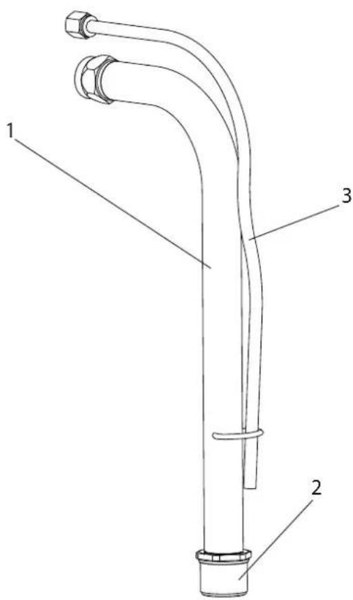
Spare parts diagram suction system
11.6 SPARE PARTS LIST HOPPER, 5 LITRES
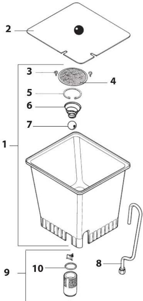
| ITEM | ORDER-NO DESIGNATION | |
| -0341 | 265 Hopper 5 | litres, assy |
| 10340 | 901 Cover | |
| 29902 | 306 Sheet metal screw 3,9x13 (2) | |
| 3 | 0037 607 | Filter disk, mesh width 0,8 mmOptional:Filter disk, mesh width 0,4 mm |
| 0003 756 | ||
| 40340 | 904 Hopper | |
| 50340 | 908 Return ube | |
Spare parts diagram hopper (5 L)
11.7 SPARE PARTS LIST HOPPER, 20 LITRES
| ITEM | ORDER-NO DESIGNATION |
| - 0341 | 266 Hopper 20 litres, assy |
| 1 0097 | 269 Hopper without cover |
| 2 0097 | 270 Cover |
| 3 9902 | 306 Sheet metal screw 3,9x13 (2) |
| 4 0097 | 521 Filter disk, mesh width 0,8 mm |
| 5 9922 | 609 Securing ring 37 x 1.5 |
| 6 0037 | 776 Pressure spring |
| 7 9941 | 509 Ball 30 |
| 8 0097 | 295 Return tube |
| 9 0097 | 271 Container adapter, assy |
| 10 9971 | 065 O-ring 44 x 3 |
Spare parts diagram hopper (20 L)
TESTING OF THE UNIT
For safety reasons, we would recommend having the device checked by an expert as required but at least every 12 months to ensure that it can continue to operate safely.
In the case of unused devices, the check can be postponed until they are next started up.
All (potentially deviating) national inspection and maintenance regulations must also be observed.
If you have any questions, please contact the customer service team at Wagner.
IMPORTANT INFORMATION ON PRODUCT LIABILITY
According to an EU directive, the manufacturer is only liable without limitation for faults in the product if all parts come from the manufacturer or have been approved by the manufacturer and have been mounted to the device and are operated properly. If third-party accessories or spare parts are used, the manufacturer is exonerated wholly or partly from his/her liability if use of the third-party accessories or spare parts have caused a defect in the product. In extreme cases, the relevant authorities can completely prohibit using the entire device.
With original WAGNER accessories and spare parts, compliance with all safety regulations is guaranteed.
NOTE ON DISPOSAL
In observance of the European Directive 2002/96/EC on waste electrical and electronic equipment and implementation in accordance with national law, this product is not to be disposed of together with household waste material but must be recycled in an environmentally friendly way!

Wagner or one of our dealers will take back your used Wagner waste electrical or electronic equipment and will dispose of it for you in an environmentally friendly way. Please ask your local Wagner service centre or dealer for details or contact us direct.
GUARANTEE DECLARATION
(Status 01.02.2009)
1. Scope of guarantee
All Wagner professional colour application devices (hereafter referred to as products) are carefully inspected, tested and are subject to strict checks under Wagner quality assurance. Wagner exclusively issues extended guarantees to commercial or professional users (hereafter referred to as “customer”) who have purchased the product in an authorised specialist shop, and which relate to the products listed for that customer on the Internet under www.wagner-group.com/profi-guarantee.
The buyer's claim for liability for defects from the purchase agreement with the seller as well as statutory rights are not impaired by this guarantee.
We provide a guarantee in that we decide whether to replace or repair the product or individual parts, or take the device back and reimburse the purchase price. The costs for materials and working hours are our responsibility. Replaced products or parts become our property.
2. Guarantee period and registration
The guarantee period amounts to 36 months. For industrial use or equal wear, such as shift operations in particular, or in the event of rentals it amounts to 12 months.
Systems driven by petrol or air are also guaranteed for a 12 month period.
The guarantee period begins with the day of delivery by the authorised specialist shop. The date on the original purchase document is authoritative.
For all products bought in authorised specialist shops from 01.02.2009 the guarantee period is extended to 24 months providing the buyer of these devices registers in accordance with the following conditions within 4 weeks of the day of delivery by the authorised specialist shop.
Registration can be completed on the Internet under www.wagner-group.com/profi-guarantee.
The guarantee certificate is valid as confirmation, as is the original purchase document that carries the date of the purchase. Registration is only possible if the buyer is in agreement with having the data being stored that is entered during registration.
When services are carried out under guarantee the guarantee period for the product is neither extended nor renewed.
Once the guarantee period has expired, claims made against the guarantee or from the guarantee can no longer be enforced.
3. Handling
If defects can be seen in the materials, processing or performance of the device during the guarantee period, guarantee
claims must be made immediately, or at the latest within a period of 2 weeks.
The authorised specialist shop that delivered the device is entitled to accept guarantee claims. Guarantee claims may also be made to the service centres named in our operating instructions. The product has to be sent without charge or presented together with the original purchase document that includes details of the purchase date and the name of the product. In order to claim for an extension to the guarantee, the guarantee certificate must be included.
The costs as well as the risk of loss or damage to the product in transit or by the centre that accepts the guarantee claims or who delivers the repaired product, are the responsibility of the customer.
4. Exclusion of guarantee
Guarantee claims cannot be considered
-for parts that are subject to wear and tear due to use or other natural wear and tear, as well as defects in the product that are a result of natural wear and tear, or wear and tear due to use. This includes in particular cables, valves, packaging, jets, cylinders, pistons, means-carrying housing components, filters, pipes, seals, rotors, stators, etc. Damage due to wear and tear that is caused in particular by sanded coating materials, such as dispersions, plaster, putty, adhesives, glazes, quartz foundation.
-in the event of errors in devices that are due to non-compliance with the operating instructions, unsuitable or unprofessional use, incorrect assembly and/or commissioning by the buyer or by a third party, or utilisation other than is intended, abnormal ambient conditions, unsuitable coating materials, unsuitable operating conditions, operation with the incorrect mains voltage supply/frequency, over-operation or defective servicing or care and/or cleaning.
-for errors in the device that have been caused by using accessory parts, additional components or spare parts that are not original Wagner parts.
-for products to which modifications or additions have been carried out.
-for products where the serial number has been removed or is illegible
-for products to which attempts at repairs have been carried out by unauthorised persons.
-for products with slight deviations from the target properties, which are negligible with regard to the value and usability of the device.
-for products that have been partially or fully taken apart.
5. Additional regulations.
The above guarantees apply exclusively to products that have been bought by authorised specialist shops in the EU, CIS, Australia and are used within the reference country.
If the check shows that the case is not a guarantee case, repairs are carried out at the expense of the buyer.
The above regulations manage the legal relationship to us concludingly. Additional claims, in particular for damages and losses of any type, which occur as a result of the product or its use, are excluded from the product liability act except with regard to the area of application.
Claims for liability for defects to the specialist trader remain unaffected.
German law applies to this guarantee. The contractual language is German. In the event that the meaning of the German and a foreign text of this guarantee deviate from one another, the meaning of the German text has priority.
J. Wagner GmbH
Division Professional Finishing
Otto Lilienthal Strasse 18
88677 Markdorf
Federal Republic of Germany
Subject to modifications · Printed in Germany
EU Declaration of conformity
We declare under sole responsibility that this product (type: D701C) conforms to the following relevant stipulations:
2006/42/EC, 2014/30/EU, 2011/65/EU, 2012/19/EU
Applied harmonised norms:
EN ISO 12100, EN 1953, EN 60204-1, EN 61000-3-2,
EN 61000-3-3, EN 61000-6-1, EN 61000-6-3
The EU declaration of conformity is enclosed with the product. If required, it can be re-ordered using order number 2403395.
3 DESCRIPTION DE L'APPAREIL
3.1 PROCÉDÉ AIRLESS
3.3 ILLUSTRATIONS DU MATÉRIEL
3.5 TRANSFORMATION DU CHARIOT
3.6 BOÎTE À OUTILS
3.7 CARACTÉRISTIQUES TECHNIQUES
Super Finish 33 Plus (Type : D701C)
Tension: 230 volts \~, 50 Hz
Fusible: 16 A lent
4.5 PRIS E ÉLECTRIQUE SUR LE GROUPE
4.8 MISE EN SERVICE DE L'APPAREIL AVEC LE PRODUIT DE REVÊTEMENT
8.4 NETTOYAGE DU PISTOLET DE PULVÉRISATION AIRLESS
10.2 VANNE D'ASPIRATION
Montage
10.4 VANNE DE RÉGLAGE DE PRESSION

10.5 REMPLACEMENT DU CORDON D'ALIMENTATION
10.7 SCHÉMA ÉLECTRIQUE
Recommendation
TEMPSPRAY
TempSpray H 226 / H 326

HEA - DES BUSES POUR UNE PULVÉRISATION SANS BROUILLARD INTEMPESTIF ET AVEC UNE BASSE PRESSION

2 Speed Tip support Réf. No. 0271065
Tableau des buses
| Taille de chantiers Produits applicables | |||
| Laque (L) Peinture (D) Enduit (S) | |||
| Petit | D5Buse: 111 / 415Réf. No. 0271 062 | S5Buse: 225 / 629Réf. No. 0271 064 | |
| D7Buse: 113 / 417Réf. No. 0271 063 | |||
| L10Buse: 208 / 510Réf. No. 0271 042 | D10Buse: 111 / 419Réf. No. 0271 045 | S10Buse: 527 / 235Réf. No. 0271 049 | |
| Moyen | L20Buse: 210 / 512Réf. No. 0271 043 | D20Buse: 115 / 421Réf. No. 0271 046 | S20Buse: 539 / 243Réf. No. 0271 050 |
| Grand | L30Buse: 212 / 514Réf. No. 0271 044 | D30Buse: 115 / 423Réf. No. 0271 047 | S30Buse: 543 / 252Réf. No. 0271 051 |
| Très grand | D40Buse: 117 / 427Réf. No. 0271 048 | ||
| Tamis de crosse recommandé rouge | blanc - | ||
11.2 LISTE DE PIÈCES DE RECHANGE SF 33 PLUS
INDICATION DE MISE AU REBUT
Division Professional Finishing
Otto Lilienthal Strasse 18
88677 Markdorf
3.3 Figure illustrative
3.4 Trasporto 115
2 PANORAMICA SULL'IMPIEGO
3 DESCRIZIONE DELL'APPARECCHIO
3.1 METODO AIRLESS
3.3 FIGURE ILLUSTRATIVE

3.6 SCATOLA ATTREZZI
3.7 DATI TECNICI
Super Finish 33 Plus (Tipo: D701C)
Tensione: 230 V AC, 50 Hz
4.5 PRESA DI CORRENTE SULL'APPARECCHIO
4.8 MESSA IN FUNZIONE DELL'APPARECCHIO CON MATERIALE DI COPERTURA
10.2 VALVOLA DI ENTRATA
Montaggio
10.4 VALVOLA REGOLATRICE DELLA PRESSIONE
10.5 SOSTITUIRE IL CAVO DI ALIMENTAZIONE ELETTRICA
10.7 SCHEMA ELETTRICO
11 RICAMBI ED ACCESSORI
11.1 ACCESSORI PER SUPER FINISH 33 PLUS
Consiglio
Avvolgitubo HR30
TEMPSPRAY
TempSpray H 226 / H 326
UGELLI HEA PER UN OVERSPRAY RIDOTTO DURANTE LO SVOLGIMENTO DI LAVORI A BASSA PRESSIONE

Division Professional Finishing
Otto Lilienthal Strasse 18
88677 Markdorf


- 10 REPARATUREN AM GERÄT 17
- 1.2 EXPLOSIONSSCHUTZ
- 3.4 TRANSPORT
- 3.6 WERKZEUGBOX
- 4.5 STECKDOSE AM GERÄT
- 10 REPARATUREN AM GERÄT
- 10.2 EINLASSVENTIL
- MONTAGE
- 10.4 DRUCKREGELVENTIL
- EMPFEHLUNG
- TEMPSPRAY
- HEA - DÜSEN FÜR NEBELARMES SPRITZEN MIT NIEDERDRUCK
- PRÜFUNG DES GERÄTES
- TRANSLATION OF THE ORIGINAL OPERATING INSTRUCTIONS
- WARNING
- ENSURE SAFETY
- CONTENTS
- 1 SAFETY REGULATIONS FOR AIRLESS SPRAYING 40
- 2 GENERAL VIEW OF APPLICATION 42
- DESCRIPTION OF UNIT 43
- 4 STARTUP 47
- 5 SPRAYING TECHNOLOGY 49
- 6 HANDLING THE HIGH-PRESSURE HOSE 49
- 7 INTERRUPTION OF WORK 49
- 8 CLEANING THE UNIT 50
- 9 SERVICING 52
- 410 REPAIRS AT THE UNIT 53
- 421 SPARE PARTS AND ACCESSORIES 58
- 1 SAFETY REGULATIONS FOR AIRLESS SPRAYING
- 1.1 FLASH POINT
- 1.2 EXPLOSION PROTECTION
- 1.3 DANGER OF EXPLOSION AND FIRE FROM SOURCES OF IGNITION DURING SPRAYING WORK
- 1.4 DANGER OF INJURY FROM THE SPRAY JET
- 1.6 RECOIL OF SPRAY GUN
- 1.7 BREATHING EQUIPMENT AS PROTECTION AGAINST SOLVENT VAPORS
- 1.8 PREVENTION OF OCCUPATIONAL ILLNESSES
- 1.10 HIGH-PRESSURE HOSE
- 1.11 ELECTROSTATIC CHARGING (FORMATION OF SPARKS OR FLAMES)
- 1.12 USE OF UNITS ON BUILDING SITES AND WORKSHOPS
- 1.13 SOCKET AT THE UNIT
- 1.14 VENTILATION WHEN SPRAYING IN ROOMS
- 1.15 SUCTION INSTALLATIONS
- 1.16 EARTHING OF THE OBJECT
- 1.17 CLEANING THE UNIT WITH SOLVENTS
- 1.18 CLEANING THE UNIT
- 1.19 WORK OR REPAIRS AT THE ELECTRICAL EQUIPMENT
- 1.20 WORK AT ELECTRICAL COMPONENTS
- 1.21 SETUP ON AN UNEVEN SURFACE
- 2 GENERAL VIEW OF APPLICATION
- 2.1 APPLICATION
- 2.2 COATING MATERIAL
- 2.2.1 COATING MATERIALS WITH SHARP-EDGED ADDITIONAL MATERIALS
- 2.2.2 TWO-COMPONENT COATING MATERIAL
- 2.2.3 FILTERING
- DESCRIPTION OF UNIT
- 3.1 AIRLESS PROCESS
- 3.2 FUNCTIONING OF THE UNIT
- 3.3 EXPLANATORY DIAGRAM
- 3.4 TRANSPORTATION
- TRANSPORTATION IN VEHICLE
- FOR CHANGING TO VERTICAL MODE
- FOR CHANGING TO HORIZONTAL MODE
- 3.6 TOOL BOX
- 3.7 TECHNICAL DATA
- SUPER FINISH 33 PLUS (TYPE: D701C)
- 4 STARTUP
- 4.1 UNIT WITH SUCTION SYSTEM
- 4.2 UNIT WITH UPPER HOPPER
- 4.3 HIGH PRESSURE HOSE AND SPRAY GUN
- 4.4 CONNECTION TO THE MAINS NETWORK
- 4.5 SOCKET ON UNIT
- 4.6 CLEANING PRESERVING AGENT WHEN STARTING-UP OF OPERATION INITIALLY
- UNIT WITH SUCTION TUBE
- UNIT WITH HOPPER
- 4.7 VENTILATE UNIT (HYDRAULIC SYSTEM) IF THE SOUND OF INLET VALVE IS NOT AUDIBLE
- 4.8 TAKING THE UNIT INTO OPERATION WITH COATING MATERIAL
- 5 SPRAYING TECHNOLOGY
- 6 HANDLING THE HIGH-PRESSURE HOSE
- 7 INTERRUPTION OF WORK
- 8 CLEANING THE UNIT
- UNIT WITH SUCTION SYSTEM
- UNIT WITH UPPER HOPPER
- 8.1 CLEANING THE UNIT FROM THE OUTSIDE
- 8.2 SUCTION FILTER
- SUCTION TUBE HOPPER
- 8.3 HIGH-PRESSURE FILTER
- 8.4 CLEANING THE AIRLESS SPRAY GUN
- INSERTION FILTER IN THE AIRLESS SPRAY GUN
- 9 SERVICING
- 9.1 GENERAL SERVICING
- MINIMUM CHECK BEFORE EVERY STARTUP
- CHECK AT PERIODICAL INTERVALS
- 9.2 HIGH-PRESSURE HOSE
- 10 REPAIRS AT THE UNIT
- 10.1 INLET VALVE PUSHER
- 10.2 INLET VALVE
- INSTALLATION
- 10.3 OUTLET VALVE
- 10.4 PRESSURE CONTROL VALVE
- 10.5 REPLACING THE POWER CABLE
- 10.6 TYPICAL WEAR PARTS
- 11 SPARE PARTS AND ACCESSORIES
- RECOMMENDATION
- FEATURES
- HOSE REEL HR30
- ADVANTAGES
- HEA NOZZLES FOR LOW-MIST SPRAYING AT LOW PRESSURE
- HEA TIP TABLE
- AIRLESS TIP TABLE
- 2SPEEDTIP
- TESTING OF THE UNIT
- IMPORTANT INFORMATION ON PRODUCT LIABILITY
- NOTE ON DISPOSAL
- GUARANTEE DECLARATION
- SCOPE OF GUARANTEE
- GUARANTEE PERIOD AND REGISTRATION
- HANDLING
- EXCLUSION OF GUARANTEE
- ADDITIONAL REGULATIONS
- EU DECLARATION OF CONFORMITY
- 3 DESCRIPTION DE L'APPAREIL
- 3.1 PROCÉDÉ AIRLESS
- 3.3 ILLUSTRATIONS DU MATÉRIEL
- 3.5 TRANSFORMATION DU CHARIOT
- 3.6 BOÎTE À OUTILS
- 3.7 CARACTÉRISTIQUES TECHNIQUES
- SUPER FINISH 33 PLUS (TYPE : D701C)
- 4.5 PRIS E ÉLECTRIQUE SUR LE GROUPE
- 4.8 MISE EN SERVICE DE L'APPAREIL AVEC LE PRODUIT DE REVÊTEMENT
- 8.4 NETTOYAGE DU PISTOLET DE PULVÉRISATION AIRLESS
- 10.2 VANNE D'ASPIRATION
- 10.4 VANNE DE RÉGLAGE DE PRESSION
- 10.5 REMPLACEMENT DU CORDON D'ALIMENTATION
- HEA - DES BUSES POUR UNE PULVÉRISATION SANS BROUILLARD INTEMPESTIF ET AVEC UNE BASSE PRESSION
- INDICATION DE MISE AU REBUT
- 2 PANORAMICA SULL'IMPIEGO
- 3 DESCRIZIONE DELL'APPARECCHIO
- 3.1 METODO AIRLESS
- 3.3 FIGURE ILLUSTRATIVE
- 3.6 SCATOLA ATTREZZI
- 3.7 DATI TECNICI
- SUPER FINISH 33 PLUS (TIPO: D701C)
- 4.5 PRESA DI CORRENTE SULL'APPARECCHIO
- 4.8 MESSA IN FUNZIONE DELL'APPARECCHIO CON MATERIALE DI COPERTURA
- 10.2 VALVOLA DI ENTRATA
- MONTAGGIO
- 10.4 VALVOLA REGOLATRICE DELLA PRESSIONE
- 10.5 SOSTITUIRE IL CAVO DI ALIMENTAZIONE ELETTRICA
- 11 RICAMBI ED ACCESSORI
- CONSIGLIO
- AVVOLGITUBO HR30
- UGELLI HEA PER UN OVERSPRAY RIDOTTO DURANTE LO SVOLGIMENTO DI LAVORI A BASSA PRESSIONE
Brand : WAGNER
Model : SuperFinish 33 Plus
Category : Paint spray