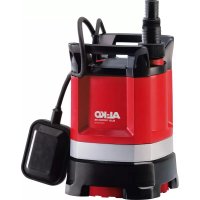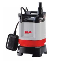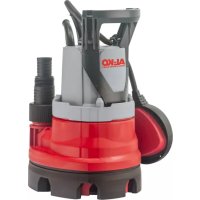
Sub 13000 DS - Pump AL-KO - Free user manual and instructions
Find the device manual for free Sub 13000 DS AL-KO in PDF.



| Product type | Submersible pump |
| Brand | AL-KO |
| Model | Sub 13000 DS |
| Category | Pump |
| Use | Indoor and outdoor domestic |
| Main functions | Water drainage, container emptying, well water extraction |
| Compatible liquids | Clear water, rainwater, chlorinated water, grey water (max 5% suspended solids) |
| Maximum liquid temperature | 35 °C |
| Thermal protection | Yes, automatic restart after cooling (15-20 min) |
| Switch type | Adjustable level switch |
| Operating mode | Automatic and manual |
| Power supply | Domestic mains 230 V (estimate) |
| Required electrical safety device | Residual current circuit breaker 30 mA, fuse 10 A |
| Minimum outdoor extension cable | 1.5 mm², type H07RN-F |
| Protection rating | IPX8 (estimate for submerged use) |
| Adjustable base | Yes, 2 positions (O and U) for residual water level |
| Maintenance | Clean the suction slots with clear water; the level switch and adjustable base can be disassembled |
| Safety | Do not use when people are in the water; disconnect before servicing; thermal protection |
| Warranty | Legal period; repair or replacement of manufacturing defects |
| After-sales service | Contact AL-KO via www.alko-garden.com/service-contacts |
| Storage | Frost-proof; drain the system before storage |
| Included accessories | Mixed fitting, level switch, adjustable base |
| Standards | Compliant with EU directives |
Frequently Asked Questions - Sub 13000 DS AL-KO
User questions about Sub 13000 DS AL-KO
0 question about this device. Answer the ones you know or ask your own.
Ask a new question about this device
Download the instructions for your Pump in PDF format for free! Find your manual Sub 13000 DS - AL-KO and take your electronic device back in hand. On this page are published all the documents necessary for the use of your device. Sub 13000 DS by AL-KO.
USER MANUAL Sub 13000 DS AL-KO
natural_image
Technical line drawing of two electrical devices connected via wires, no text or symbols present





DE
GB
NL
FR
ES
IT
SI
HR
PL
CZ
SK
HU
DK
SE
NO
FI
EE
LT
LV
BG
RU
UA
TR
RO
Inhaltsverzeichnis
Deutsch 8
English....15
Nederlands 22
Français....29
Español 37
Italiano 44
Slovenščina 51
Hrvatski....58
Polski....65
Česky 73
Slovenská 80
Magyar 87
Dansk 94
Svensk....101
Norsk 108
Suomi 115
Eesti 122
Lietuvių 129
Latviešu 136
български 143
Русский 151
Україна....159
Türkçe 167
Român 174
© 2024
AL-KO KOBER GROUP Kötz, Germany
This documentation or excerpts therefrom may not be reproduced or disclosed to third parties without the express permission of the AL-KO KOBER GROUP.
text_image
A 1 2 3 4 5 6 7 8 9 10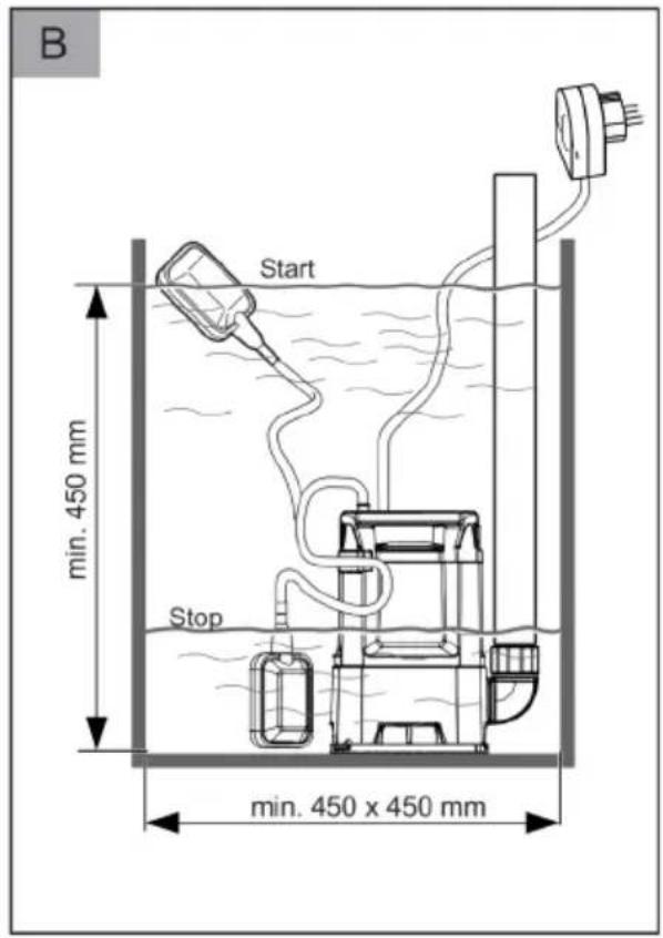
text_image
B Start min. 450 mm Stop min. 450 x 450 mm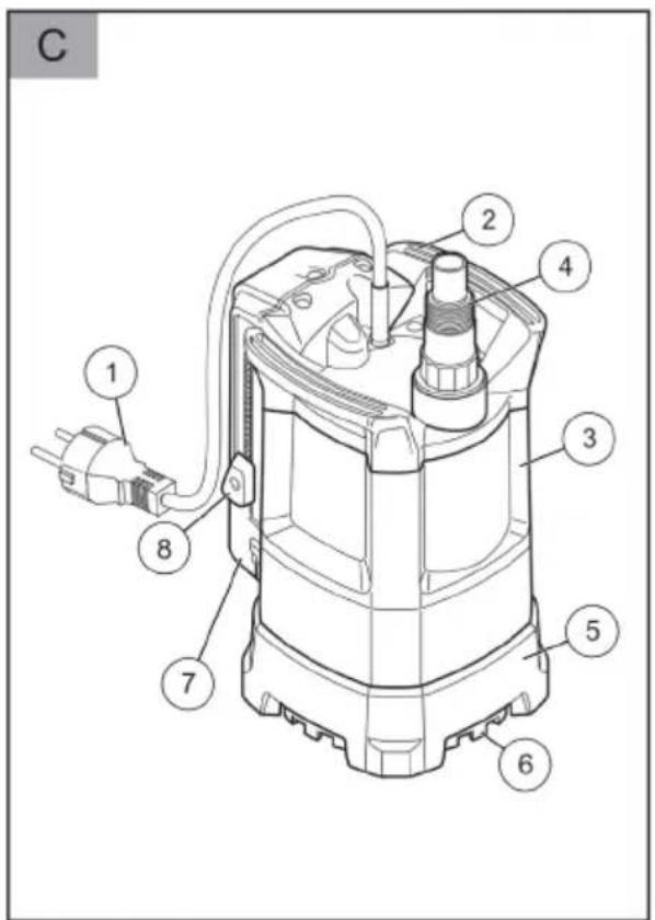
text_image
C 1 2 4 3 5 6 7 8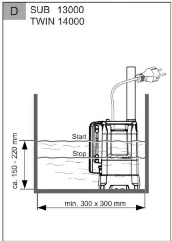
text_image
D SUB 13000 TWIN 14000 Start Stop ca. 150 - 220 mm min. 300 x 300 mm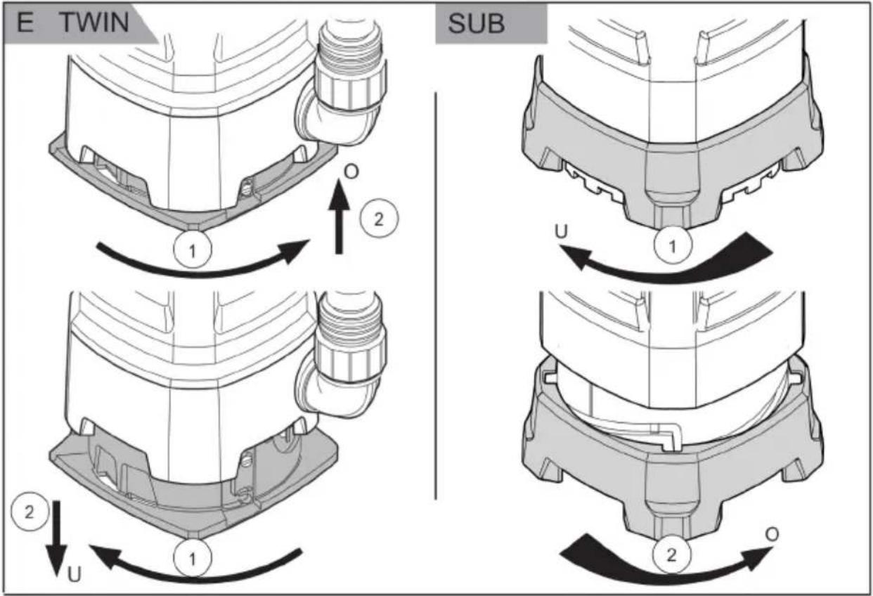
text_image
E TWIN SUB 1 2 U 2 U 2 O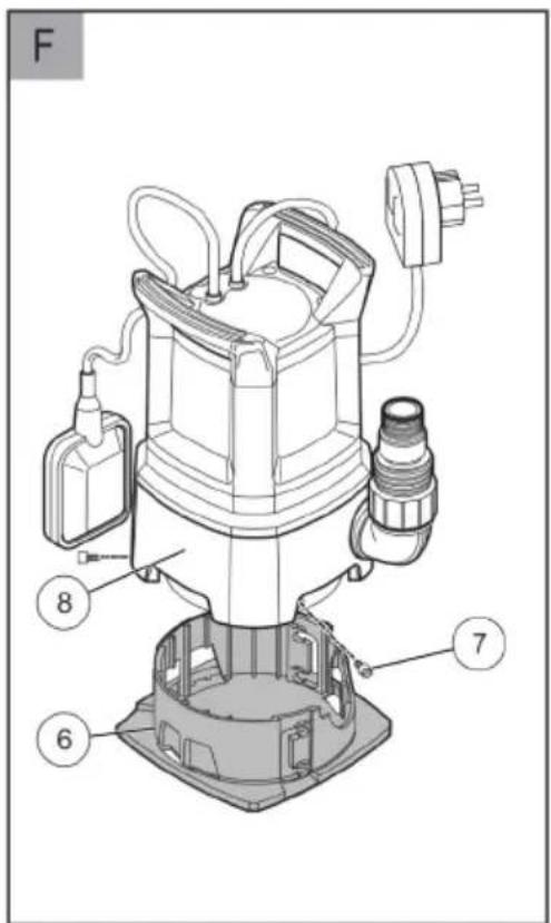
text_image
F 8 6 7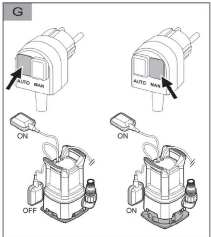
text_image
G AUTO MAN AUTO MAN ON OFF ON ON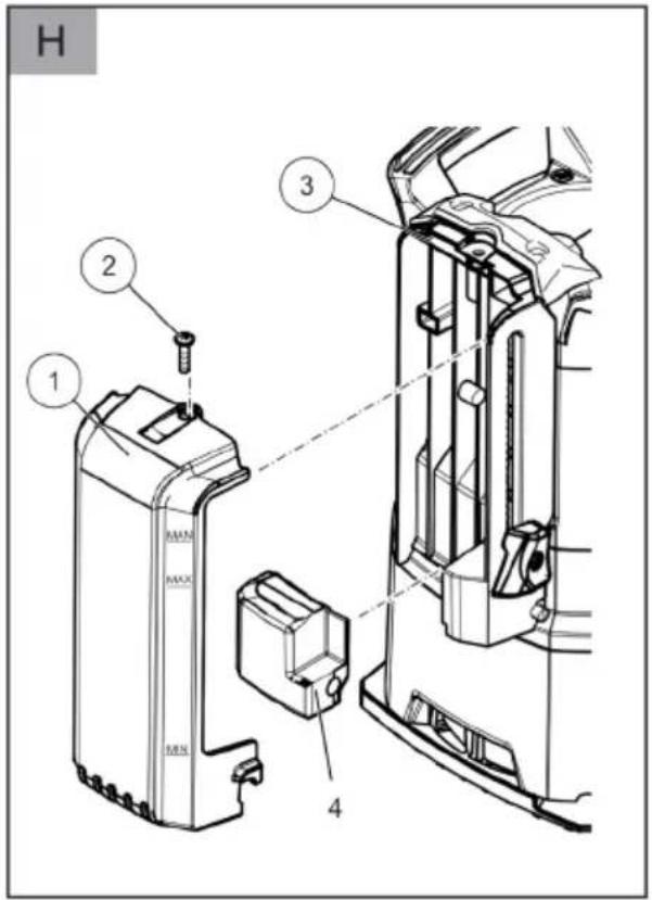
text_image
H 1 2 3 4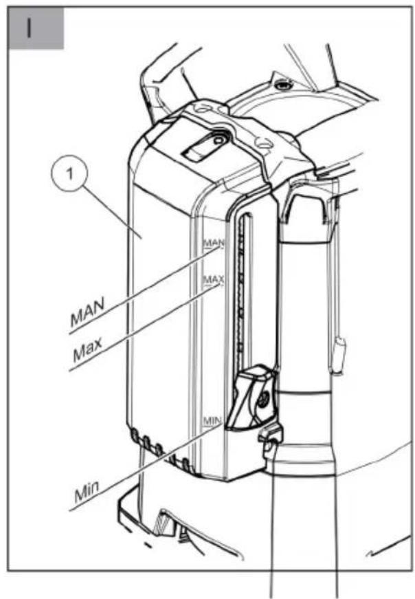
text_image
1 MAN MAX MIN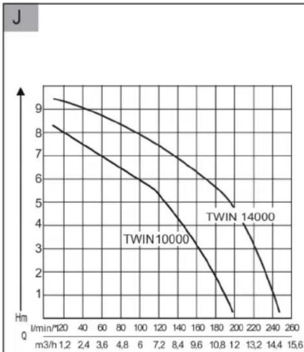
line
| m3/h | TWIN 10000 | TWIN 14000 | |------|------------|------------| | 1.2 | 9.5 | 8.5 | | 2.4 | 9.2 | 8.0 | | 3.6 | 8.8 | 7.5 | | 4.8 | 8.3 | 7.0 | | 6 | 7.8 | 6.5 | | 7.2 | 7.3 | 6.0 | | 8.4 | 6.8 | 5.5 | | 9.6 | 6.3 | 5.0 | | 10.8 | 5.8 | 4.5 | | 12 | 5.3 | 4.0 | | 13.2 | 4.8 | 3.5 | | 14.4 | 4.3 | 3.0 | | 15.6 | 3.8 | 2.5 |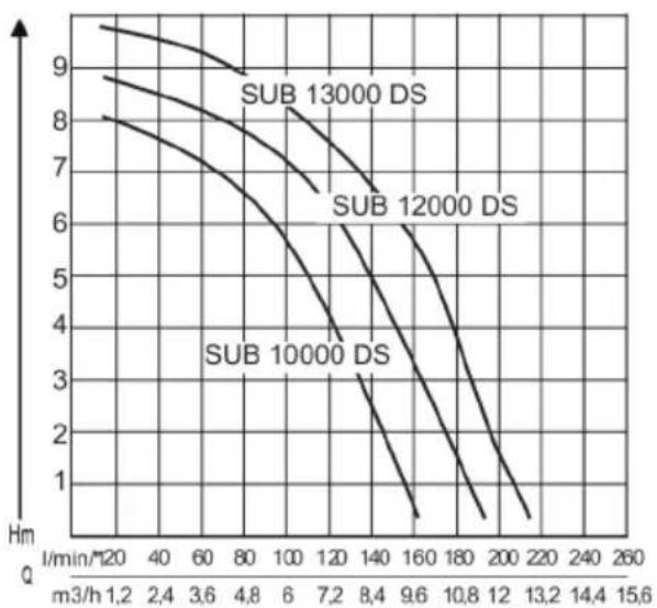
line
| m3/h | Sub 10000 DS | Sub 12000 DS | Sub 13000 DS | |------|--------------|--------------|--------------| | 1.2 | 8.1 | 8.9 | 9.5 | | 2.4 | 7.8 | 8.6 | 9.3 | | 3.6 | 7.5 | 8.3 | 9.1 | | 4.8 | 7.2 | 8.0 | 8.9 | | 6 | 6.8 | 7.6 | 8.7 | | 7.2 | 6.4 | 7.2 | 8.5 | | 8.4 | 6.0 | 6.8 | 8.3 | | 9.6 | 5.5 | 6.4 | 8.1 | | 10.8 | 5.0 | 6.0 | 7.9 | | 12 | 4.5 | 5.6 | 7.7 | | 13.2 | 4.0 | 5.2 | 7.5 | | 14.4 | 3.5 | 4.8 | 7.3 | | 15.6 | 3.0 | 4.4 | 7.1 |
| SUB 10000 DS(Art. Nr. 112 823)SUB 12000 DS(Art. Nr. 112 824)SUB 13000 DS(Art. Nr. 112 829)(Klarwasser) | TWIN 11000 (Art.Nr. 112 830)TWIN 14000 (Art.Nr. 112 831)(Klar-/Schmutzwasser) | SUB 11000(Art. Nr. 113 508)(Klarwasser) | |
 | SUB 10000 DS: 450 WSUB 12000 DS: 550 WSUB 13000 DS: 650 W | TWIN 11000: 850 WTWIN 14000: 1000 W | 520 W |
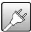 | 230 V AC/50 Hz 230 V AC/50 Hz 230 V AC/50 Hz | ||
 | X 8 X 8 X 8 | ||
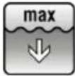 | 5 m 7 m 5 m | ||
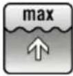 | SUB 10000 DS: 7 mSUB 12000 DS: 8 mSUB 13000 DS: 8 m | TWIN 11000: 10 mTWIN 14000: 10 m | 8 m |
 | SUB 10000 DS: 8000 l/hSUB 12000 DS: 9500 l/hSUB 13000 DS: 10500 l/h | TWIN 11000: 13500 l/hTWIN 14000: 15000 l/h | 9000 l/h |
 | 35 °C 35 °C 35 °C | ||
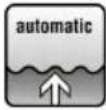 | 2,5 cm TWIN 11000: 5,0 cmTWIN 14000: 6,0 cm | 2,5 cm | |
 | 3 mm TWIN 11000: 20 mmTWIN 14000: 30 mm | 3 mm | |
 | SUB 10000 DS: 5,5 kgSUB 12000 DS: 5,8 kgSUB 13000 DS: 6,0 kg | TWIN 11000: 7,2 kgTWIN 14000: 8,4 kg | 5,8 kg |
 | 3 mm 8 mm 3 mm | ||
 | SUB 10000 DS cm:37/15 - 39/17SUB 12000 DS cm:37/15 - 39/17SUB 13000 DS cm:13,5-21,5/11,5 -15,5-23,5/13,5 | TWIN 11000 cm:41/22 - 46/27TWIN 14000 cm:17,0-25,0/15,0 -21,3-29,3/19,3 | 37/15 - 39/17 |
 | 10 m 10 m 10 m | ||
1 About these operating instructions...... 15
1.1 Symbols on the title page 15
1.2 Legends and signal words...... 15
2 Product description 16
2.1 Product overview 16
2.1.1 TWIN (Figure A) 16
2.1.2 SUB (Figure C).... 16
2.2 Function.... 16
2.3 Position of adjustable foot.... 16
2.4 Thermal protection.... 16
2.5 Designated use.... 16
2.6 Possible misuse.... 16
3 Safety instructions.... 17
3.1 General safety warnings.... 17
3.2 Electrical safety.... 17
4 Installation.... 18
4.1 Fitting the pressure line 18
4.1.1 TWIN (Figure A) 18
4.1.2 SUB (Figure C).... 18
4.2 Adjustment of adjustable foot (Figure E) 18
4.2.1 TWIN 18
4.2.2 SUB.... 18
5 Start-up 18
5.1 Safety.... 18
6 Operation 18
6.1 Switching the pump on 18
6.2 Switching the pump off 18
6.3 Automatic mode.... 18
6.4 Manual operation mode.... 19
6.5 Pumping out to residual water level... 19
7 Maintenance and care.... 19
7.1 Cleaning the pump.... 19
7.2 Removing/fitting the level switch..... 19
7.3 Removing/fitting the adjustable foot... 19
8 Help in case of malfunction.... 19
9 Storage.... 20
10 Disposal.... 20
11 After-Sales/Service.... 20
12 Information on the Declaration of Confor-
mity 21
13 Warranty 21
1 ABOUT THESE OPERATING INSTRUCTIONS
The German version is the original operating instructions. All additional language versions are translations of the original operating instructions.
- Keep these operating instructions in a safe place at all times so that they can be consulted if you need any information about the appliance.
■ Only pass on the appliance to other persons together with these operating instructions.
■ Comply with the safety and warning information in these operating instructions.
1.1 Symbols on the title page
Symbol Meaning

It is essential to read through these operating instructions carefully before start-up. This is essential for safe working and trouble-free handling.

Operating instructions
To avoid electric shock, do not damage or cut the power cable!
1.2 Legends and signal words
⚠️ DANGER! Denotes an imminently dangerous situation which will result in fatal or serious injury if not avoided.
WARNING! Denotes a potentially dangerous situation which can result in fatal or serious injury if not avoided.
CAUTION! Denotes a potentially dangerous situation which can result in minor or moderate injury if not avoided.
IMPORTANT! Denotes a situation which can result in material damage if not avoided.
NOTE Special instructions for ease of understanding and handling.
2 PRODUCT DESCRIPTION
Various models of pumps are described in these operating instructions. Identify your model from the identification plate.
2.1 Product overview
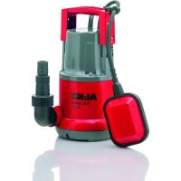
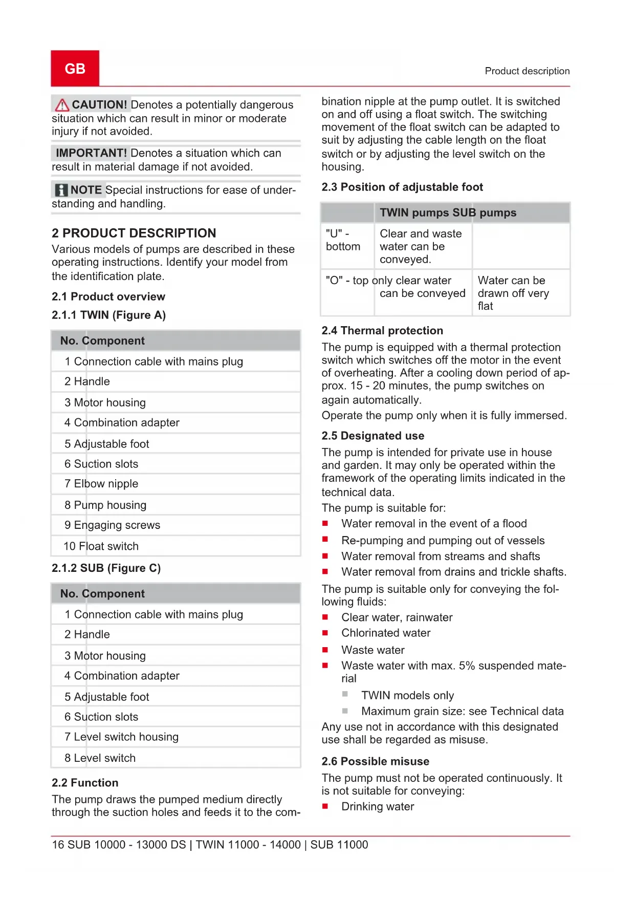
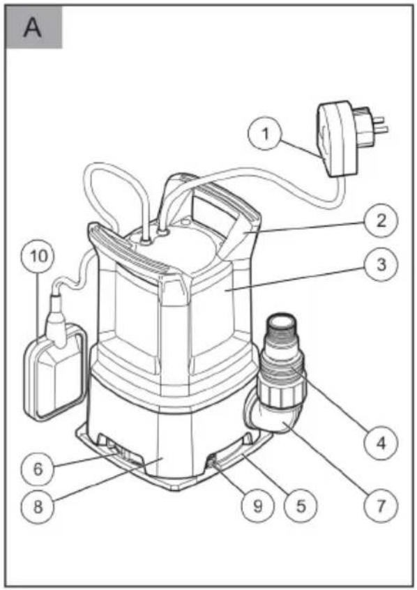
2.1.1 TWIN (Figure A)
No. Component
| 1 Connection cable with mains plug |
| 2 Handle |
| 3 Motor housing |
| 4 Combination adapter |
| 5 Adjustable foot |
| 6 Suction slots |
| 7 Elbow nipple |
| 8 Pump housing |
| 9 Engaging screws |
| 10 Float switch |
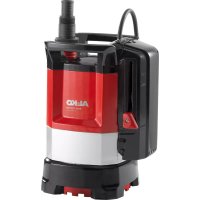
2.1.2 SUB (Figure C)
No. Component
| 1 Connection cable with mains plug |
| 2 Handle |
| 3 Motor housing |
| 4 Combination adapter |
| 5 Adjustable foot |
| 6 Suction slots |
| 7 Level switch housing |
| 8 Level switch |
2.2 Function
The pump draws the pumped medium directly through the suction holes and feeds it to the com-
bination nipple at the pump outlet. It is switched on and off using a float switch. The switching movement of the float switch can be adapted to suit by adjusting the cable length on the float switch or by adjusting the level switch on the housing.
2.3 Position of adjustable foot
| TWIN pumps SUB pumps | ||
| "U" - bottom | Clear and waste water can be conveyed. | |
| "O" - top only clear water can be conveyed | Water can be drawn off very flat | |
2.4 Thermal protection
The pump is equipped with a thermal protection switch which switches off the motor in the event of overheating. After a cooling down period of approx. 15 - 20 minutes, the pump switches on again automatically.
Operate the pump only when it is fully immersed.
2.5 Designated use
The pump is intended for private use in house and garden. It may only be operated within the framework of the operating limits indicated in the technical data.
The pump is suitable for:
■ Water removal in the event of a flood
■ Re-pumping and pumping out of vessels
■ Water removal from streams and shafts
■ Water removal from drains and trickle shafts.
The pump is suitable only for conveying the following fluids:
Clear water, rainwater
Chlorinated water
Waste water
■ Waste water with max. 5% suspended material
TWIN models only
■ Maximum grain size: see Technical data
Any use not in accordance with this designated use shall be regarded as misuse.
2.6 Possible misuse
The pump must not be operated continuously. It is not suitable for conveying:
- Drinking water
Salt water
Foodstuffs
■ aggressive media, chemicals
■ corrosive, flammable, explosive or fuming fluids
■ fluids that are hotter than 35 °C
■ water containing sand and abrasive fluids.
3 SAFETY INSTRUCTIONS
⚠️ DANGER! Danger from contact with live parts! A defect in the pump or the extension cable can result in serious injury!
■ Disconnect the connector plug from the mains immediately.
■ Connect the device via an earth leakage circuit breaker with a rated leakage current of < 30 mA.
WARNING! Risk of injury. Defective and disabled safety and protective devices can result in serious injury.
■ Have any defective safety and protective devices repaired.
■ Never disable safety and protective devices.
CAUTION! Risk of burns from hot water!
After extended use against the closed pressure side (> 10 min.), the water in the pump can become very hot and may escape uncontrolled!
■ Disconnect the pump from the mains supply and allow the pump and water to cool down.
- Check the water level on the suction side.
- Check the leak-tightness of the lines.
- Check the installation of the suction and pressure lines.
- Put the pump into operation again only after all the faults have been remedied!
3.1 General safety warnings
■ Appliances can be used by persons with reduced physical, sensory or mental capabilities or lack of experience and knowledge if they have been given supervision or instruction concerning use of the appliance in a safe way and if they understand the hazards involved. Children shall not play with the appliance.
■ People with very strong and complex restrictions may have needs that exceed the instructions described here.
■ Pumps without indication that they are protected against the effect of freezing shall not be left outside during freezing weather conditions.
■ Never lift, transport or affix the pump by the mains cable. Do not pull the mains cable in order to pull the mains plug out of the socket.
■ Unauthorised modifications or conversions to the pump are prohibited. Repairs may only be carried out by our customer service.
■ Disconnect the mains plug before working on the device. Protect the mains plug against moisture.
■ Only use the pump and extension cable if they are in flawless technical condition. Damaged appliances must not be operated.
- Maintain a safe distance to persons or animals or switch off the pump if animals approach.
3.2 Electrical safety
■ The pump may not be operated while people are in the pool or pond.
The mains voltage at your location must comply with the information regarding mains voltage in the Technical Data. Do not use any other supply voltage.
The pump may only be operated on an electrical installation in accordance with DIN/VDE 0100, parts 737, 738 and 702. For fuse protection, a circuit breaker of 10 A and an earth leakage circuit breaker with a rated leakage current of 10/30 mA must be installed.
■ Only use extension leads approved for outdoor use with a minimum cross-section of 1.5 mm ^4 . Always fully unwind cable drums.
■ Damaged or fragile extension cables may not be used.
- Check the condition of your extension lead prior to every use.
If the connection cable must be extended, only a cable type H07RN-F and a moulded sleeve must be used. This work must only be carried out by an electrician.
If the supply cord is damaged, it must be replaced by the manufacturer, its service agent or similarly qualified persons in order to avoid a hazard.
4 INSTALLATION
4.1 Fitting the pressure line
4.1.1 TWIN (Figure A)
- Screw connecting bracket (7) into the pump outlet.
- Bolt combination nipple (4) to the connecting bracket.
- Connect hose to combination nipple.
4.1.2 SUB (Figure C)
- Bolt combination nipple (4) to the connecting bracket.
- Connect hose to combination nipple.
NOTE The combination nipple can be trimmed to suit the selected hose connection. Use the largest possible hose diameter.
4.2 Adjustment of adjustable foot (Figure E)
4.2.1 TWIN
- Turn adjustable foot (6) to the right. The adjustable foot is disengaged.
- Move adjustable foot to position "O" or "U".
- Turn adjustable foot to the left. The adjustable foot engages again.
4.2.2 SUB
- Turn the adjustable foot 90^ to the left to move the adjustable foot to the top position.
- Turn the adjustable foot 90^ to the right to move the adjustable foot to the bottom position.
NOTE The combination nipple can be trimmed to suit the selected hose connection. Use the largest possible hose diameter.
5 START-UP
5.1 Safety
IMPORTANT! Risk of flooding! In the event of faults in the pump, water can escape and cause consequential damage due to flooding.
■ Take appropriate measures to avoid consequential damage caused by flooding in the event of faults in the pump.
- Operate the pump suspended from a cable or pay attention top a stable position of the pump.
■ Operate the pump only when it is fully immersed.
■ Make sure there is adequate clearance under the pump.
■ Never allow the pump to run against a closed pressure line.
- When using in shafts, make sure the size is adequate.
■ Always cover the shaft with a secure foot-plate.
6 OPERATION
6.1 Switching the pump on
IMPORTANT! Danger of damage to the pump! The pump must not draw in any solid material. Sand and other abrasive materials in the pumped medium will destroy the pump.
■ Ensure that no solids can enter the pumped medium.
- Completely unwind mains cable (1).
- Ensure that electrical plug connections are located in the area safe from flooding.
Models with float switch
- Change the clamping position and set the switching points of float switch (10) individually.
- Clamp cable of float switch to the pump housing. Recommended cable length on the float switch approx. 100 mm.
Models with level switch
NOTE Use a suitable plate to ensure stable standing of the pump on muddy, sandy or stony ground.
- Push level switch (8) to the corresponding height to set the switching points.
- Slowly immerse the pump in the pumped medium, holding the pump at a slight angle so that any trapped air can escape.
- Insert the mains plug into the power socket.
The pump switches on automatically using the float switch when a specific water level has been reached, and switches off again if the water drops below the switch-off height.
6.2 Switching the pump off
- Remove the mains plug from the plug socket.
6.3 Automatic mode
-
In automatic mode, set the adjustable foot to position "U" (bottom) to achieve the greatest possible feed rate.
-
Insert the mains plug into the power socket.
Models with float switch
- Turn the operating mode selector switch on the mains switch to "AUTO" (Fig. G).
Models with level switch
- Push the level switch upwards to the desired switch-on height (Fig. I).
The pump is switched on automatically by the float switch at a specific water level (switch-on height) and switches off again when the water level falls to the switch-off height, see technical data.
6.4 Manual operation mode
In manual mode, the water can be pumped away to a very low level of residual water.
Minimum water level for commissioning: see Technical data.
6.5 Pumping out to residual water level
IMPORTANT! Danger of damage to the pump! There is a danger during pumping out that the pump could run dry and cause equipment damage.
■ Monitor the pump continuously when pumping out to the residual water level and avoid the pump running dry.
■ Take the pump out of service when the residual water level is reached by pulling out the mains plug.
Set the adjustable foot to the "O" (top) position for pumping out to the residual water level:
- Remove the mains plug from the plug socket.
Models with float switch
- Turn the operating mode selector switch to "MAN" (Fig. G). The pump switches on and starts to feed.
Models with level switch
- Push the level switch upwards to the "MAN" position (Fig. I).
NOTE If the water drops below the residual water level, the pump will draw air in. In this case, the pump must be vented when the water level rises and before using it again.
7 MAINTENANCE AND CARE
7.1 Cleaning the pump
NOTE After conveying swimming pool water containing chlorine or fluids that leave residues, the pump must be flushed out with clear water.
- Clean the suction slots on the suction foot with clear water, if necessary.
7.2 Removing/fitting the level switch
- Unscrew mounting bolt (2), then push housing level switch(1) upwards and then tilt to the front.
- Clean the float (4) and guides (3).
- Place the float back in the guide.
- Replace the housing level switch and push downwards.
- Screw in the mounting bolt.
7.3 Removing/fitting the adjustable foot
TWIN pump
- Unscrew engaging screws (7) and pull adjustable foot (6) out of pump housing (8).
- Clean adjustable foot and pump housing.
- Insert adjustable foot in pump housing, align and screw in engaging screws again.
8 HELP IN CASE OF MALFUNCTION
DANGER! Danger of electric shock!
There is a risk of electric shock when working on the pump.
■ Disconnect the mains plug before starting any fault remedying work.
■ Faults in the electrical system must be rectified by a qualified electrician.
NOTE In the event of faults that you cannot rectify, please contact our Customer Service department.
| Malfunction Possible cause | Remedy | |
| Motor does not run. Impeller blocked. Remove dirt from the suction area. | ||
| Only pumps with level switch | ||
| Pump running continuously. | Float body blocked.Switch set incorrectly. | Clean the float body.Adjust the switch correctly. |
| Pump is always off. Float body | blocked.Water level too low. | Clean the float body. |
9 STORAGE
i NOTE If there is the danger of frost, the system must be completely drained and the pump must be stored in a frost-proof place.
10 DISPOSAL

Electrical and electronic appliances do not belong in household waste, but should be collected and disposed of separately.
Packaging, equipment and accessories are made from recyclable materials, and must be disposed of accordingly.
11 AFTER-SALES/SERVICE
In the event of questions of warranty, repair or spare parts, please contact your nearest AL-KO Service Centre. These can be found on the Internet at: www.alko-garden.com/service-contacts
Further information on spare parts can be found at: www.alko-garden.com/spareparts
12 INFORMATION ON THE DECLARATION OF CONFORMITY
We hereby declare, as the exclusively responsible party, that this product in its marketed form
meets the requirements of the harmonised EU Directives, EU safety standards and the product-specific standards. The Declaration of Conformity forms part of the operating instructions and is included with the machine.
13 WARRANTY
We will remedy any material or manufacturing defects discovered in the device during the statutory period of limitation for claims for defects by repair or replacement at our discretion. The period of limitation is determined in each case by the law of the country in which the device was purchased.
Our warranty promise applies only if:
■ These operating instructions are observed
■ The device is handled correctly
■ Original spare parts have been used
The warranty becomes void in the case of:
■ Unauthorised repair attempts
■ Unauthorised technical modifications
■ Use for other than the intended purpose
The warranty does not include:
■ Paint damage attributable to normal wear
■ Wear parts that are marked with a box xxxxxx (x) on the spare parts card
The warranty period commences with the purchase by the first end user. The date on the proof of purchase is decisive. In the event of a warranty claim, please contact your dealer or the nearest authorised customer service centre with this declaration and the original proof of purchase. This declaration does not affect the purchaser's statutory claims for defects against the vendor.
VERTALING VAN DE ORIGINELE GEBRUIKERSHANDLEIDING
Inhoudsopgave
2 PRODUCTBESCHRIJVING
2.1.2 SUB (Figure C)
N° Pièce
4.1.2 SUB (Figure C)
11 SERVISNA SLUŽBA/SERVIS
7 VEDLIKEHOLD OG PLEIE
7.1 Rengjøre pumpen
Imported by: AL-KO Gardentech UK Ltd, Murray way, Wincanton, Somerset, BA9 9RS / UK | +44 (0) 1963 828055
shop.uk@al-ko.com | www.alko-garden.uk
AL-KO Service: www.al-ko.com/service-contacts