
ZIFKS315 - Saw Zipper - Free user manual and instructions
Find the device manual for free ZIFKS315 Zipper in PDF.
| Product type | Table saw |
| Brand | Zipper |
| Model | ZIFKS315 |
| Dimensions (L x W x H) | 1000 x 650 x 850 mm |
| Table dimensions | 800 x 350 mm |
| Carriage dimensions | 1000 x 300 mm |
| Net weight | 65.5 kg |
| Voltage / Frequency | 230 V / 50 Hz |
| Motor power | 1.8 kW |
| Motor speed | 2800 rpm |
| Saw blade | ∅315 x ∅30 x 3 x 2 mm |
| Max cutting capacity (90°) | 73 mm |
| Max cutting capacity (45°) | 49 mm |
| Dust extraction connection diameter | ∅100 mm and ∅35 mm |
| Sound power level | 108.8 dB(A) |
| Protection class | I |
| Intended use | For cutting wood only |
| Included components | Aluminum table, legs with wheels, precision carriage, parallel and cross guide, ∅315 mm saw blade, manual |
| Recommended maintenance | Check screws before each operation, clean after each use |
| Warranty | 2 years for DIY use, 1 year for industrial use |
Frequently Asked Questions - ZIFKS315 Zipper
User questions about ZIFKS315 Zipper
0 question about this device. Answer the ones you know or ask your own.
Ask a new question about this device
Download the instructions for your Saw in PDF format for free! Find your manual ZIFKS315 - Zipper and take your electronic device back in hand. On this page are published all the documents necessary for the use of your device. ZIFKS315 by Zipper.
USER MANUAL ZIFKS315 Zipper
natural_image
Green ZIPPER industrial machine with cutlery and wheels, no visible text or symbols on the device itself.ZI-FKS315
EAN: 9120039238371
1 INHALT /INDEX
12.1 Components (Fig. 1 and 2)....31
12.2 Delivery content....31
12.3 Technical details 32
13 SAFETY 33
13.1 Intended Use.... 33
13.2 Security instructions 34
13.3 Remaining risks 35
14 ASSEMBLY 36
14.1 Assembly....36
14.1.1 Setting up the machine (Fig. 3-8) ......36
14.1.2 Fitting and removing oft he saw blade guard (Fig. 9)....36
14.1.3 Dismantling the sliding table and opening the chip box (Fig. 12, 13) ......36
14.1.4 Mounting the table extension....36
15 OPERATION 37
15.1 Operation instructions.... 37
15.2 Adjustments for starting up 37
15.2.1 Setting the splitter (Fig. 14, 15)....37
15.2.2 Adjustment of the cutting depth (Fig. 17) ......37
15.2.3 Setting the blade angle (Fig. 17)....37
15.2.4 Rip fence 37
15.2.5 Cross stop and sliding table (Fig. 27)....38
15.3 Operation 38
15.3.1 Switching ON/OFF (Fig. 10)....38
15.3.2 Longitudinal cuts (Fig.22) 38
15.3.3 Working with the sliding table....38
16 MAINTENANCE 39
16.1 Changing of the saw blade (Fig. 16)....39
16.2 Maintenance plan....39
16.3 Cleaning 39
16.4 Storage 39
16.4.1 Using the chassis (Fig. 11)....39
16.5 Disposal 40
17 TROUBLE SHOOTING 40
18 PREFACIO (ES) 41
19 TÉCNICA 42
19.1 Datos técnicos....42
19.2 Entrega de la mercancía....42
19.3 Componentes 43
EN CE-Conformal! - This product complies with the EC-directives.
EN ATTENTION! Ignoring the safety signs and warnings applied on the machine as well as ignoring the security and operating instructions can cause serious injuries and even lead to death.
EN READ THE MANUAL! Read the user and maintenance manual carefully and get familiar with the controls in order to use the machine correctly and to avoid injuries and machine defects.
EN Protective clothing!
EN Stop and pull out the power plug before any break and engine maintenance!
EN Operation with gloves forbidden!
EN Only trained staff!
EN Operation with jewelry forbidden!
EN Operation with tie forbidden!
EN Operation with long hair forbidden!
EN Warning about cut injuries!
EN Protect from moisture!
EN Make sure that there are no other persons inside the danger zone (minimum distance 2m) in the danger zone.


natural_image
Person using a cutting machine on a flat workbench, no visible text or symbols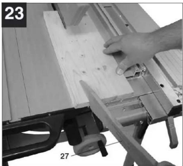
natural_image
Close-up of a hand using a tool to cut or spread material on a wooden cutting board, with no visible text or symbols.

natural_image
Close-up of a printer's paper being cut with a cloth, showing paper and mechanical components (no text or symbols visible)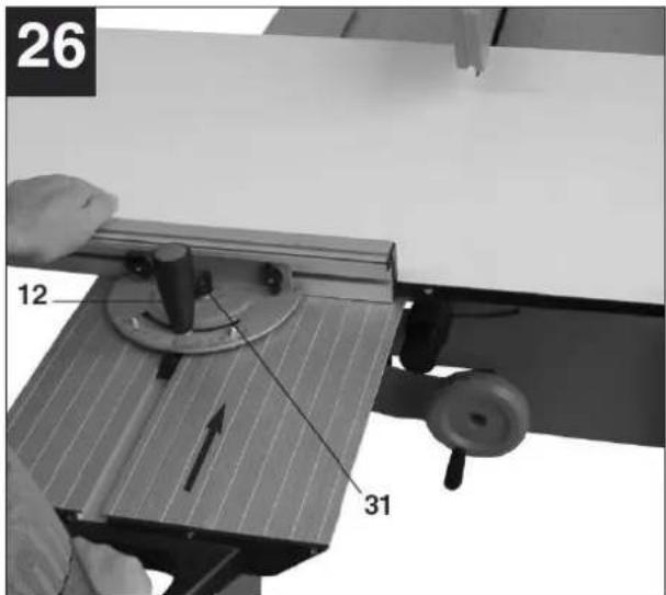

natural_image
Person using a flatboard on an open bench, with a hand pressing down (no visible text or symbols)4 TECHNIK
natural_image
Metallic component with labeled section B1, showing layered structure (no text or symbols beyond label)
natural_image
Close-up of a mechanical component with mounting holes and a curved tool, labeled 'Abbildung 1' (no other text or symbols visible)
natural_image
Close-up of a mechanical component with no visible text or symbols, labeled 'Abbildung 3' at bottom left (no other text or symbols)8 BETRIEB
This manual contains information and important instructions for the installation and correct use of the panel saw ZI-FKS315.
Following the usual commercial name of the device (see cover) is substituted in this manual with the name "machine".
This manual is part of the product and shall not be stored separately from the product. Save it for later reference and if you let other people use the product, add this instruction manual to the product.

Please read and obey the security instructions!
Before first use read this manual carefully. It eases the correct use of the product and prevents misunderstanding and damages of product and the user's health.
Due to constant advancements in product design, construction pictures and content may diverse slightly. However, if you discover any errors, inform us please.
Technical specifications are subject to changes!
Please check the product contents immediately after receipt for any eventual transport damage or missing parts.
Claims from transport damage or missing parts must be placed immediately after initial product receipt and unpacking before putting the product into operation.
Please understand that later claims cannot be accepted anymore.
Copyright
© 2016
This manual is protected by copyright law – all rights reserved. Especially the reprinting as well as the translation and depiction of pictures will be prosecuted by law. Court of jurisdiction is the Landesgericht Linz or the competent court for 4707 Schlüsslberg, AUSTRIA.
Customer service contact
12.1 Components (Fig. 1 and 2)
| 1 | Saw table |
| 2 | Saw blade guard |
| 3 | Sliding table |
| 4 | Saw blade |
| 5 | Splitter |
| 6 | Longitudinal fence |
| 7 | Cross fence |
| 8 | Cutting depth adjustment |
| 9 | Angle setting |
| 11 | ON/OFF switch |
| 12 | Clamping screw |
| 13 | Extractor hose |
| 14 | Dust collector plug |
| 15 | Wheels |
| 16 | Handles |
| 17 | Chip box |
| 18 | Legs |
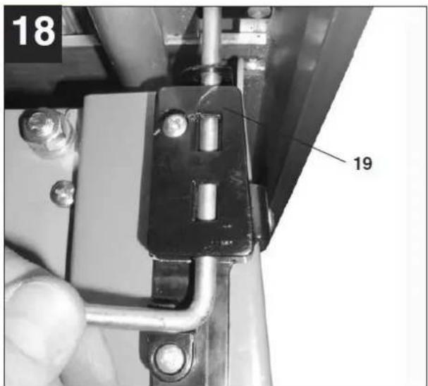
| 19 | Table lock |
| 23 | Mounting |
| 25 | Rubber feet |
| 28 | Hook for tool |
| 29 | Mounting for extractor hose |
12.2 Delivery content
| 1 | Stable saw table made of high-quality aluminium profile |
| 2 | Stand with wheels |
| 3 | Precise sliding table |
| 4 | Aluminium longitudinal and cross fence |
| 5 | Saw blade ∅315 mm |
| 6 | User manual |
12.3 Technical details
| Voltage | 230 V/50 Hz |
| Engine power | 2 kW |
| Engine speed | 2800 min ^-1 |
| Table size | 800x350 mm |
| Sliding table size | 1000x300 mm |
| Dust collector plug | ∅100 / ∅35 mm |
| Saw blade | ∅315x∅30x3 mm |
| Throat | 600 mm |
| Max. cutting height (90°) | 73 mm |
| Max. cutting height (45°) | 49 mm |
| Sound pressure level | 96,2 dB(A) |
| Sound power level | 103 dB(A) |
| Dimensions | 1000x650x850 mm |
| Packing size | 1110x740x410 mm |
| weight (net/gross) | 65,5/70 kg |
13 SAFETY
13.1 Intended Use
The machine must only be used for its intended purpose! Any other use is deemed to be a case of misuse.
To use the machine properly you must also observe and follow all safety regulations, the assembly instructions, operating and maintenance instructions lay down in this manual.
All people who use and service the machine have to be acquainted with this manual and must be informed about the machine's potential hazards.
It is also imperative to observe the accident prevention regulations in force in your area.
The same applies for the general rules of occupational health and safety.
The machine is used for:
Cutting of wood and wood like materials
Any manipulation of the machine or its parts is a misuse, in this case ZIPPER - MASCHINEN and its sales partners cannot be made liable for any direct or indirect damage.

WARNING
- Use only saw blades allowable for this machine (EN 847-1)!
- Never use damaged saw blades!
- Never use the machine with defective or without mounted guard
- The removal or modification of the safety components may result in damage to equipment and serious injury!
HIGHEST RISK OF INJURY!
Ambient conditions:
The machine may be operated:
humidity
max. 70%
temperature
+5^ to +40^ (+41^ to +104^)
The machine shall not be operated outdoors or in wet or damp areas.
The machine shall not be operated in areas exposed to increased fire or explosion hazard.
Prohibited use:
- The operation of the machine outside the stated technical limits described in this manual is forbidden.
- The operation of the machine without provided protective devices is prohibited
- The use of the machine not according with the required dimensions is forbidden.
- The use of the machine not being suitable for the use of the machine and not being certified is forbidden.
- Any manipulation of the machine and parts is forbidden.
- The unattended operation on the machine during the working process is forbidden!
- It is not allowed to leave the immediate work area during the work is being performed!
13.2 Security instructions
Missing or non-readable security stickers have to be replaced immediately! The locally applicable laws and regulations may specify the minimum age of the operator and limit the use of this machine!
To avoid malfunction, machine defects and injuries, read the following security instructions!


- Keep your work area dry and tidy! An untidy work area may cause accidents. Avoid slippery floor!
- Make sure the work area is lighted sufficiently!
• Work only in a well ventilated area! - Do not overload the machine!
- Avoid abnormal working postures! Make sure you stand squarely and keep balance at all times.
- Keep away from the running saw blade!
- Always stay focused when working. Reduce distortion sources in your working environment. The operation of the machine when being tired, as well as under the influence of alcohol, drugs or concentration influencing medicaments is forbidden.
- Only one person shall operate the machine
- The machine must be operated only by trained persons (knowledge and understanding of this manual), which have no limitations of motor skills compared with conventional workers.
• Make your workshop childproof!
• Make sure there is nobody present in the dangerous area. The minimum safety distance is 2m - Wear suitable work clothes! Do not wear loose clothing or jewelry as they might be caught and cause severe accidents!
- Wear a hair net if you have long hair!
- Loose objects can become entangled and cause serious injuries!
- Use personal safety equipment: ear protectors, safety goggles, work wear, safety gloves (EN 388, class 3111) dust mask when working with or on the machine.
• Operation with gloves forbidden!
• Gloves may only used at maintenance work and changing the saw blade - Never leave the machine running unattended! Before leaving the working area switch the machine off and wait until the machine stops Die laufende Maschine darf nie unbeaufsichtigt sein!
• Always disconnect the machine prior to any actions performed at the machine. - Avoid unintentional starting
- Do not use the machine with damaged switch
- The plug of an electrical tool must strictly correspond to the socket. Do not use any adapters together with earthed electric tools
• Each time you work with an electrically operated machine, caution is advised! There is a risk of electric shock, fire, cutting injury; - Protect the machine from dampness (causing a short circuit)!
- Use power tools and machines never in the vicinity of flammable liquids and gases (danger of explosion)!
- Check the cable regularly for damage
- Do not use the cable to carry the machine or to fix the work piece
- Protect the cable from heat, oil and sharp edges
13.3 Remaining risks

WARNING
It is important to ensure that each machine has remaining risks. In the execution of all work (even the simplest) greatest attention is required. A safe working depends on you!
Even if the machine is used as required it is still impossible to eliminate certain residual risk factors totally. The following hazards may arise in connection with the machine's construction and design:
- Risk of injury to the hands / fingers by the rotating saw blade during operation.
- Risk of injury due to sharp edges of the workpiece, especially in non-fixed with a suitable tool / device workpiece
- Risk of injury: hair and loose clothing, etc. can be captured and wound up! Safety regulations must be observed with regard to clothing.
- Risk of injury due to contacting with live electrical components.
- Risk of injury due to dust emissions, treated with harmful agents workpieces
- Risk of injury to the eye by flying debris, even with safety goggles.
- Risk of injury due to kickback:
Kickback is a sudden reaction to a jamming, grinding or staggered blade. This causes the ejection of the workpiece to the direction of the operator.
These risk factors can be minimized through obeying all security and operation instructions, proper machine maintenance, proficient and appropriate operation by persons with technical knowledge and experience.


NOT ICE
Emergency procedure
A first aid kit in accordance with should always be readily available for a possible accident. Initiate the violation in accordance with the necessary first aid measures. When requesting support, provide the following details:
- Place of accident
- Number of injured people
- Type of accident
- Injury type(s)
14 ASSEMBLY
Please check the product contents immediately after receipt for any eventual transport damage or missing parts. Claims from transport damage or missing parts must be placed immediately after initial machine receipt and unpacking before putting the machine into operation. Please understand that later claims cannot be accepted anymore.
14.1 Assembly
14.1.1 Setting up the machine (Fig. 3-8)
Place the table saw with the table touching the floor on a flat floor. Fix the four legs 18 in the inside of the main body with four screws (SW13) for every leg (Fig. 3). When you insert the legs you have to look that they are exactly in the related curbs. Mount the four rubber feet 25 on the legs (Fig. 8). Fix the wheels 15 on the legs at the inside with two screws for every leg. The four spacers 26 must be inserted between the legs and the angle bracket 22 (Fig. 4). When assembling, make sure that the rounded side of the angle bracket faces the bottom of the machine. Turn the saw upside down and place it on the floor. Now insert the sliding table 3 carefully into the slide ways 24 and push the sliding table to the point where the locking hook latches 10 (Fig. 5) home. Now screw the mount for the extractor hose 29 and the tool hook 28 on the main body of the machine 1 (Fig. 6, 7).
14.1.2 Fitting and removing oft he saw blade guard (Fig. 9)
Mount the blade guard 2 on the splitter 5, so that the screw 37 fits through the hole 45. Don't tighten the screw too tight - the saw blade guard has to be able to be moved freely. Fit the extractor hole 13 on the extractor adapter 14 and the extractor socket of the blade guard 2.
Important: The blade guard has to be lowered over the work piece before cutting.
14.1.3 Dismantling the sliding table and opening the chip box (Fig. 12, 13)
Pull the sliding table 3 back till you can see the locking hook 10. Press down on the locking hook 10 with one hand and at the same time use the other hand to pull the sliding table forward and out of the guide 24 (Fig. 12). Now remove the two screws b (Fig. 13) and flip open the chip box.
Tip: The screws are removed easier if there will be adjusted an angle of about 45^ . For the fitting you have to do these steps backwards.
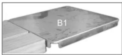
14.1.4 Mounting the table extension
Mount the table extension like shown on the below pictures.
natural_image
Metallic component with labeled section B1, showing internal structure and edge details (no text beyond label)
natural_image
Close-up of a mechanical component with mounting holes and a curved handle, labeled 'Abbildung 1' (no other text or symbols visible)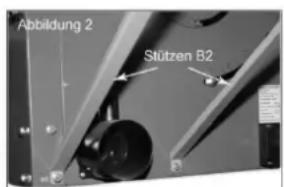
natural_image
Close-up of a mechanical component with no visible text or symbols, labeled 'Abbildung 3' at bottom left (no other readable text or symbols)15 OPERATION
Device to be operated in a perfect state only. Inspect the device visually every time it is to be used. Check in particular the safety equipment, electrical controls, electric cables and screwed connection for damage and if tightened properly. Replace any damaged parts before operating the device.
15.1 Operation instructions
 | WARNING |  |
| Perform all machine settings with the machine being disconnected from the power supply! |

NOT ICE
- Operating only with started dust collector!
- Never start the machine when the workpiece is pressed to the saw blade!
• Before starting the machine check if the saw blade is tightened
• Always adapt cutting speed to the respective working
• Use the push stick to avoid the risk of contact with the saw blade - Slide the workpiece evenly, without relapses and without retake it until the end of cutting.
15.2 Adjustments for starting up
15.2.1 Setting the splitter (Fig. 14, 15)
Set the blade 4 to its maximum cutting depth, move it to its 0° position and lock it (see 2.6.2 and 2.6.3). Remove the saw blade guard (see 2.5.3). Remove the sliding table and open the chip box (See 2.5.3). Loosen the screw 38 with the included tool 40 (Fig. 40). Pull up the splitter till the distance between the saw table 1 and the top point of the splitter is at its maximum. The maximum distance between the splitter and the saw blade is 8mm (Fig. 15). Now fit the nut again and mount all the parts, being removed.
15.2.2 Adjustment of the cutting depth (Fig. 17)
Turn the hand crank 8 to set the required depth.
Turning clock wise: smaller cutting depth.
Turning anti-clock wise: bigger cutting depth.
15.2.3 Setting the blade angle (Fig. 17)
Loosen the lock screw 9. Turn the hand crank 9 to set the required angle on the scale b. Then tighten the screw again.
15.2.4 Rip fence
- Stop height (Fig. 19, 20)
The fence has two different guiding areas. Fort hick materials it must be used like shown in Fig. 22 and for thin ones like shown in Fig. 23
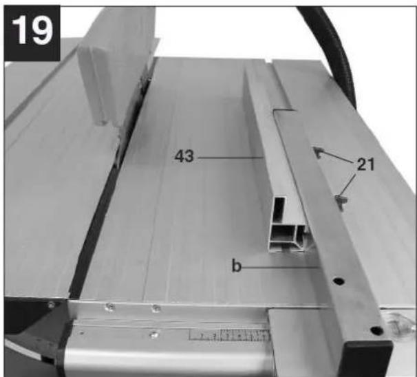
• Cutting width (Fig. 19, 20)
The fence 7 must be used for longitudinal cuts in wooden work pieces. It should be mounted on the right side of the blade 4. It must be pushed into the guide 17 outside. Adjust the required distance and lock the fence with the lock screw.
- Setting the stop length
The stop rail can be moved on the work piece to prevent the work piece from becoming jammed.
Rule of thumb: The rear end of the stop comes up against an imaginary line that begins roughly at the center of the saw blade and runs at an angle of 45^ to the rear.
At first set the cutting width. Then loosen the nuts 21 and pull the stop rail forwards till it reaches the imaginary line. Tighten the nuts again.
15.2.5 Cross stop and sliding table (Fig. 27)
Push the cross stop 7 into the groove a of the sliding table. Loosen the lock screw 12 and turn it till the arrow points at the required angle.
Important: Don't pull the stop rail too far to the saw blade. The distance between the rail and the saw blade 4 should be about 2cm.
Tighten the lock screw again.
15.3 Operation
15.3.1 Switching ON/OFF (Fig. 10)
For turning on the machine the cover must be opened and the green button must be pushed. This one is on the switch panel 11. Let the engine get to its maximum speed before cutting.
Important: The cover must be flapped down again because it's used as emergency stop switch. For turning off you have to push the red button.
15.3.2 Longitudinal cuts (Fig.22)
For longitudinal cuts the sliding table must be fixed with the lock 19 (Fig. 18). Press one edge of the work piece against the longitudinal fence while the flat side lies on the saw blade. The blade guard always has to lie on the work piece. Adjust the fence. Turn on the machine. Place your hands (with fingers closed) flat on the work piece and pull it along the fence into the blade. Lead on the side with your hands always only to the position of the front edge of the blade guard.
Always push the work piece through to the end of the splitter. The offcut piece remains on the saw table 1 until the blade is back in its position of rest.
• Cutting narrow work pieces:
Always use a push block 3 when the cutting width is lower than 120mm.
Important: Always replace a damaged push block through a new one.
• Cutting extremely narrow work pieces (Fig. 23):
Use a push block when the cutting width is lower than 30mm. Use the longitudinal fence like shown in Fig. 23.
- Making concealed nuts
Remove the saw blade guard (see 2.5.2). Adjust the cutting depth and the splitter new. Pull the work piece into the blade. After cutting the blade guard must be fitted again.
- Making bevel cuts (Fig. 25):
Adjust the required angle. The cut follows like a normal cut.
15.3.3 Working with the sliding table
- Cross cuts (Fig. 26, 27): Pull the sliding table forward. Set the cross stop to the required angle and fix it with the lock screw on the sliding table. Press the work piece against the cross stop and move the sliding table slowly forwards. Turn off the machine and remove the offcut when the saw blade is in its position of rest.
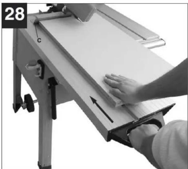
- Making edging cuts: Place the work piece on the sliding table and press it against the edging plate c. Pull the sliding table forwards and make the cut.
16 MAINTENANCE

ATTENTI ON
Perform all maintenance machine settings with the machine being disconnected from the power supply!
Serious injury due to unintentional or automatic activation of the machine!

The machine does not require intense maintenance. However, to ensure a long lifespan, we strongly recommend following the upkeep and maintenance plan.
Repairs must be carried out by specialists!
16.1 Changing of the saw blade (Fig. 16)

NOTICE
Wear safety gloves when you work with saw blades!
Set the maximum cutting depth. Remove the blade guard and the sliding table. Then open the chip box. Use the two included tools 40, 41 to loosen the screw 42. Change the blades.
Important: Clean the flange before fitting the new blade.
Important: Note the running direction! The cutting angle of the teeth must point in running direction (see the arrow on the chip box). Do these steps backwards for fitting the new saw blade..
16.2 Maintenance plan
| Loose or lost screws, nuts, bolts | Regularly prior to each operation |
| Damage of any part of the machine | Regularly prior to each operation |
| Machine cleaning | Regularly after operation |
16.3 Cleaning
Clean the machine from dirt, chippings, etc ... Clean the machine housing with a wet cloth and a mild cleaning solution.

IMPORTANT
The usage of solvents, aggressive chemicals or scouring agents damages the machine housing.
16.4 Storage
Always store your machine in clean, dry rooms and cover it with a tuck. For the transport you have to use the wheels
16.4.1 Using the chassis (Fig. 11)
To swing the chassis out, gently lift the saw at the back and push the wheels backwards 15. Then lower the saw. It is now standing on the wheels and can be transported by one person with the aid of the handles 16 easily. Important: Never lift the saw by the sliding table!
Important: After the transport the chassis must be retracted in order to ensure that the saw is standing securely. To do this, return the wheels to their starting position by following the sequence in reverse.
16.5 Disposal
Do not dispose the machine in residual waste. Contact your local authorities for information regarding the available disposal options. When you buy at your local dealer for a replacement unit, the latter is obliged to exchange your old.

17 TROUBLE SHOOTING
BEFORE YOU START WORKING FOR THE ELIMINATION OF DEFECTS, DISCONNECT THE MACHINE FROM THE POWER SUPPLY.
| PROBLEM | CAUSE | SOLUTION |
| Saw does not start. | Motor cord or wall cord is not plugged in.Circuit fuse is blown.Circuit breaker is tripped.Cord or switch is damaged. | Plug in motor cord or wall cord.Replace circuit fuse.Reset circuit breaker.Have the cord or switch replaced. |
| Rip fence does not move smoothly. | Rip fence not mounted correctly.Rails are dirty or sticky.Clamp screw is out of adjustment. | Remount the rip fence.Clean and wax rails.Adjust clamp screw. |
| Rip fence does not lock at rear. | Clamp screw is out of adjustment. | Adjust clamp screw. |
| Cutting binds or burns work. | Blade is dull.Working is fed too fast.Rip fence is misaligned.Spreader is out of alignment.Wood is warped. | Replace or sharpen blade.Slow the feed rate.Align the rip fence.Replace the wood. Always cut with convex side to table surface. |
| Wood edges away from rip fence when ripping.Saw does not make accurate 90°or 45° cuts. | Ripping fence is misaligned.Positive stops inside cabinet need adjusting(Bevel Cuts).Miter gauge is misaligned(Miter Cuts). | Check and adjust the rip fence.Adjust positive stops.Adjust the miter gauge. |
| Height/bevel adjusting handwheel is hard to turn. | Gears or post inside cabinet are clogged with saw dust. | Clean the gears or screw post. |
| Blade makes poor cuts. | Blade is dull or dirty.Blade is wrong type for cut being made.Blade is mounted backwards. | Clean, sharpen, or replace blade.Replace with correct type.Remount blade. |
| Blade does not lower when turning height /bevel adjusting handwheel. | Locking lever is not at full left position. | Move locking lever to left. |
| Motor labors in rip cut. | Blade not proper for rip out. | Change blade; rip blade typically has fewer teeth. |
MANY POTENTIAL SOURCES OF ERROR CAN BE CLEARED BY THE EXPERTLY CONNECTION TO THE ELECTRICITY GRID.

NOTICE
Should you in necessary repairs not able to properly to perform or you have not the prescribed training for it always attract a workshop to fix the problem.
18 PREFACIO (ES)
Estimado Cliente,
56 ERSATZTEILE / SPARE PARTS
With original Zipper spare parts you use parts that are attuned to each other shorten the installation time and elongate your products lifespan.
IMP OR TAN T
The installation of other than original spare parts voids the warranty!
So you always have to use original spare parts
When you place a spare parts order please use the service formular you can find in the last chapter of this manual. Always take a note of the machine type, spare parts number and partname. We recommend to copy the spare parts diagram and mark the spare part you need.
You find the order address in the preface of this operation manual.
| No. | Code | Qty | No. | Code | Qty |
| 1 | DT/01-009 | 4 | 56 | RTS315F04013 | 1 |
| 2 | TJ315E01002-4 | 4 | 57 | TJ250A02012-1 | 1 |
| 3 | GB6170-M6 | 9 | 58 | TJ250A02012-2 | 1 |
| 4 | RTS315FA01030 | 4 | 59 | GB802-M4 | 1 |
| 5 | GB97.1-6 | 12 | 60 | DJ315S02001-16 | 4 |
| 6 | GB5781-M6X16 | 8 | 61 | GB96-6 | 3 |
| 7 | RTS315F06028 | 2 | 62 | TJ315B04013 | 1 |
| 8 | GB5780-M6X45 | 2 | 63 | GB12-M6X25 | 2 |
| 9 | TJ315A06013 | 2 | 64 | TJ315B04015 | 2 |
| 10 | TJ315A06014 | 2 | 65 | RTS315FA04006 | 1 |
| 11 | GB889-M6 | 4 | 66 | TJ315A08025 | 1 |
| 12 | GB5781-M8X16 | 6 | 67 | TJ315A08027 | 1 |
| 14 | GB97.1-8 | 10 | 68 | RTS315F06029 | 1 |
| 15 | GB6170-M8 | 8 | 69 | GB5781-M6X12 | 3 |
| 16 | KJD18 | 1 | 70 | GB846-ST3.5X16C | 3 |
| 17 | GB845-ST4.2X13C | 3 | 71 | GB845-ST3.5X13C | 1 |
| 18 | RTS315F06019 | 1 | 72 | RTS315F06006 | 1 |
| 19 | 1 | 73 | 1 | ||
| 20 | DLMB025 | 1 | 74 | TJ315G02006 | 1 |
| 21 | 31505010 | 2 | 75 | GB12618-4X13 | 1 |
| 21 | RTS315F06018 | 1 | 76 | RTS315F06010 | 1 |
| 22 | DLMB026 | 1 | 77 | GB12-M6X35 | 1 |
| 23 | TJ315S05010 | 1 | 78 | RTS315FA06007 | 1 |
| 25 | RTS315F03051 | 1 | 79 | RTS315F01021 | 1 |
| 27 | GB5781-M6X20 | 2 | 80 | GB845-ST2.9X10C | 1 |
| 28 | GB97.1-4 | 3 | 81 | GB62-M6 | 1 |
| 29 | GB276-605-2Z | 2 | 82 | RTS315F01051 | 1 |
| 32 | GB819-M4X6 | 3 | 83 | GB801-M6X16 | 1 |
| 33 | RTS315F01022 | 1 | 84 | RTS315F01050A | 1 |
| 34 | RTS315F01020 | 1 | 85 | RTS315F01041 | 1 |
| 37 | QKS8 | 1 | 86 | GB845-ST4.2X9C | 2 |
| 39 | GB862.1-4 | 1 | 87 | RTS315F01040 | 1 |
| 40 | GB6170-M4 | 4 | 88 | RTS315F06005 | 1 |
| 41 | GB5781-M5X12 | 1 | 89 | 1 | |
| 42 | GB6170-M5 | 2 | 90 | RTS315F01043 | 1 |
| 43 | GB93-5 | 3 | 91 | DJ315S02001-18 | 2 |
| 44 | GB97.1-5 | 5 | 92 | TJ315S04003 | 1 |
| 45 | RTS315FA01026 | 2 | 93 | RTS315FA04003 | 1 |
| 46 | LM-20 OP | 4 | 94 | DJ315S02001-20 | 1 |
| 47 | GB17880.1 M8X15 | 1 | 95 | GB12-M6X55 | 1 |
| 48 | GB5781 M6X45 | 1 | 96 | GB70-M5X8 | 1 |
| 49 | RTS315FA01028 | 8 | 98 | RTS315FA01031 | 1 |
| 50 | GB70.3 M5X25 | 4 | 99 | RTS250G04011 | 1 |
| 51 | RTS315FA01024 | 8 | 100 | RTS315FA01011 | 1 |
| 52 | GB/T119 8X50 | 2 | 101 | RTS315FA01001 | 1 |
| 53 | RTS315FA01027 | 2 | 102 | TJ315B04016 | 1 |
| 54 | RTS315F04005 | 1 | 103 | GB845-ST4.8X13C | 1 |
| 55 | RTS315F04012 | 1 | 104 | RTS315F06022 | 1 |
| 105 | RTS315F06009 | 1 | 152 | RTS315F03014 | 2 |
| 106 | RTS250G04002-1 | 1 | 153 | GB70.3-M6X25 | 2 |
| 107 | GB12-M6X20 | 2 | 154 | RTS315F03015 | 2 |
| 108 | RTS315FA04001 | 1 | 155 | RTS315F03023 | 1 |
| 109 | RTS315F01042 | 1 | 156 | GB96 8 | 1 |
| 110 | RTS250G04002-2 | 1 | 157 | DT/SB030 | 1 |
| 111 | GB818-M4X8 | 2 | 158 | TJ315S06007 | 1 |
| 112 | RTS315F01003-2 | 1 | 159 | DT/SB031 | 5 |
| 113 | GB70-M5X10 | 2 | 160 | RTS315FA03019A | 1 |
| 114 | TJ20005001 | 1 | 161 | RTS315F03018 | 2 |
| 115 | TJ20007001/ | 1 | 162 | RTS315F03022 | 1 |
| 116 | RTS315F01046 | 1 | 163 | GB818-M6X20 | 2 |
| 117 | RTS315F03021 | 2 | 164 | RTS315F03024 | 1 |
| 118 | RTS315F01056 | 2 | 165 | RTS315C03016 | 1 |
| 119 | RTS315FA01029 | 1 | 166 | TJ315A03011 | 1 |
| 120 | GB818-M4X10 | 1 | 167 | RTS315M02011A | 1 |
| 121 | RTS250G06010 | 1 | 168 | RTS315F02015 | 1 |
| 122 | RTS315FA06031 | 1 | 169 | GB6170-M12 | 1 |
| 123 | TJ250G04012 | 1 | 170 | GB97.1-12 | 1 |
| 124 | TJ315G06010 | 1 | 171 | TJ315B02003 | 1 |
| 125 | TJ250D04013 | 1 | 172 | TJ315E02004 | 1 |
| 126 | RTS315F06003 | 1 | 173 | TJ315A02002 | 1 |
| 127 | GB818-M4X10 | 2 | 174 | GB96-8 | 2 |
| 128 | TJ31506014 | 1 | 175 | GB802-M8 | 2 |
| 129 | TJ315G06004 | 1 | 176 | GB6172-M8 | 2 |
| 130 | TJ315E06004A | 1 | 177 | GB93-6 | 1 |
| 132 | RTS315F06014 | 1 | 178 | RTS315F06015 | 1 |
| 133 | RDC100T-01-01 | 1 | 179 | GB12-M12X40 | 1 |
| 134 | TJ315E06005A | 1 | 180 | RTS315F03002 | 1 |
| 135 | GB97.1-20 | 1 | 181 | RTS315F03001 | 1 |
| 136 | GB/T91 4X30 | 1 | 182 | GB5781-M8X30 | 1 |
| 137 | RTS315FA01002 | 1 | 183 | TJ315A03029 | 1 |
| 138 | TJ315A06021 | 1 | 184 | YYL8032T-T | 1 |
| 140 | RTS315F01003-1 | 1 | 185 | RTS315F03010 | 1 |
| 141 | RTS315F06026 | 1 | 186 | RTS315F06031 | 1 |
| 142 | RTS315F01045 | 1 | 187 | RTS315F06002 | 1 |
| 143 | GB5782 M10X50 | 1 | 188 | RTS315F03012 | 1 |
| 144 | AC2401603C | 1 | 189 | RTS315F03013 | 1 |
| 145 | GB6172 M10 | 1 | 190 | GB276-6000-2Z | 1 |
| 146 | GB97.1 10 | 1 | 191 | GB879-4X25 | 1 |
| 147 | TJ315B06012A | 1 | 192 | RTS315FA03011 | 1 |
| 148 | TJ315A06017 | 1 | 193 | RTS315F06011 | 1 |
| 149 | TJ315E06006 | 1 | 194 | GB70.3-M6X75 | 1 |
| 150 | 1 | 196 | TJ25003004-2 | 1 | |
| 151 | GB819-M6X16 | 2 | 197 | RTS315F06017-1 | 1 |
58 GEWÄHRLEISTUNG
1.) Gewährleistung:
Company ZIPPER Maschinen GmbH grants for mechanical and electrical components a warranty period of 2 years for amateur use; and warranty period of 1 year for professional use, starting with the purchase of the final consumer. In case of defects during this period, which are not excluded by paragraph 3, ZIPPER will repair or replace the machine at its own discretion.
2.) Report:
In order to check the legitimacy of warranty claims, the final consumer must contact his dealer. The dealer has to report in written form the occurred defect to ZIPPER. If the warranty claim is legitimate, ZIPPER will pick up the defective machine from the dealer. Returned shippings by dealers which have not been coordinated with ZIPPER, will not be accepted and refused.
3.) Regulations:
a) Warranty claims will only be accepted, when a copy of the original invoice or cash voucher from the trading partner of ZIPPER is enclosed to the machine. The warranty claim expires if the accessories belonging to the machine are missing.
b) The warranty does not include free checking, maintenance, inspection or service works on the machine. Defects due to incorrect usage of the final consumer or his dealer will not be accepted as warranty claims either. Some examples: usage of wrong fuel, frost damages in water tanks, leaving fuel in the tank during the winter, etc.
c) Defects on wear parts are excluded, e.g. carbon brushes, collection bags, knives, cylinders, cutting blades, clutches, sealings, wheels, saw blades, splitting crosses, riving knives, riving knife extensions, hydraulic oils, oil/air/fuel filters, chains, spark plugs, sliding blocks, etc.
d) Also excluded are damages on the machine caused by incorrect or inappropriate usage, if it was used for a purpose which the machine is not supposed to, ignoring the user manual, force majeure, repairs or technical manipulations by not authorized workshops or by the customer himself, usage of non-original ZIPPER spare parts or accessories.
e) After inspection by our qualified personnel, resulted costs (like freight charges) and expenses for not legitimated warranty claims will be charged to the final customer or dealer.
f) In case of defective machines outside the warranty period, we will only repair after advance payment or dealer's invoice according to the cost estimate (incl. freight costs) of ZIPPER.
g) Warranty claims can only be granted for customers of an authorized ZIPPER dealer who directly purchased the machine from ZIPPER. These claims are not transferable in case of multiple sales of the machine.
4.) Claims for compensation and other liabilities:
The liability of company ZIPPER is limited to the value of goods in all cases. Claims for compensation because of poor performance, lacks, damages or loss of earnings due to defects during the warranty period will not be accepted. ZIPPER insists on its right to subsequent improvement of the machine
60 GARANTÍA Y SERVICIO
1.) Garantía:
We observe the quality of our delivered products in the frame of a Quality Management policy.
Your opinion is essential for further product development and product choice. Please let us know about your:
- Impressions and suggestions for improvement.
- experiences that may be useful for other users and for product design
- Experiences with malfunctions that occur in specific operation modes
We would like to ask you to note down your experiences and observations and send them to us via FAX, E-Mail or by post:
Erworben von / purchased from:
E-Mail/ e-mail:
service inquiry spare part inquiry guarantee claim
Please describe amongst others in the problem: What has cause the problem/defect, what was the last activity before you noticed the problem/defect? For electrical problems: Have you had checked you electric supply and the machine already by a certified electrician?
3. Bitte beachten
/ Additional information
INCOMPLETELY FILLED SERVICE FORMS CANNOT BE PROCESSED! FOR GUARANTEE CLAIMS PLEASE ADD A COPY OF YOUR ORIGINAL SALES / DELIVERY RECEIPT OTHERWISE IT CANNOT BE ACCEPTED. FOR SPARE PART ORDERS PLEASE ADD TO THIS SERVICE FORM A COPY OF THE RESPECTIVE EXPLODED DRAWING WITH THE REQUIRED SPARE PARTS BEING MARKED CLEARLY AND UNMISTAKABLE. THIS HELPS US TO IDENTIFY THE REQUIRED SPARE PARTS FASTLY AND ACCEL- LERATES THE HANDLING OF YOUR INQUIRY.


- ZI-FKS315
- INHALT /INDEX
- SAFETY 33
- ASSEMBLY 36
- OPERATION 37
- MAINTENANCE 39
- TROUBLE SHOOTING 40
- PREFACIO (ES) 41
- TÉCNICA 42
- TECHNIK
- BETRIEB
- Please read and obey the security instructions!
- Copyright
- Customer service contact
- SAFETY
- Intended Use
- WARNING
- Ambient conditions:
- Prohibited use:
- Security instructions
- Remaining risks
- NOT ICE
- Emergency procedure
- ASSEMBLY
- Assembly
- Setting up the machine (Fig. 3-8)
- Fitting and removing oft he saw blade guard (Fig. 9)
- Dismantling the sliding table and opening the chip box (Fig. 12, 13)
- Mounting the table extension
- OPERATION
- Operation instructions
- Adjustments for starting up
- Setting the splitter (Fig. 14, 15)
- Adjustment of the cutting depth (Fig. 17)
- Setting the blade angle (Fig. 17)
- Rip fence
- Cross stop and sliding table (Fig. 27)
- Operation
- Switching ON/OFF (Fig. 10)
- Longitudinal cuts (Fig.22)
- Working with the sliding table
- MAINTENANCE
- ATTENTI ON
- Changing of the saw blade (Fig. 16)
- NOTICE
- Maintenance plan
- Cleaning
- IMPORTANT
- Storage
- Using the chassis (Fig. 11)
- Disposal
- TROUBLE SHOOTING
- PREFACIO (ES)
- Estimado Cliente,
- ERSATZTEILE / SPARE PARTS
- IMP OR TAN T
- The installation of other than original spare parts voids the warranty!
- GEWÄHRLEISTUNG
- 1.) Gewährleistung:
- 2.) Report:
- 3.) Regulations:
- 4.) Claims for compensation and other liabilities:
- GARANTÍA Y SERVICIO
- 1.) Garantía:
- Bitte beachten
- / Additional information
Brand : Zipper
Model : ZIFKS315
Category : Saw