
TempSpray H326 - Paint spray WAGNER - Free user manual and instructions
Find the device manual for free TempSpray H326 WAGNER in PDF.
| Product Type | Heated paint hose for Airless spraying |
| Brand | Wagner |
| Model | TempSpray H326 |
| Maximum service pressure | 25 MPa (250 bar) |
| Power supply voltage | 230 V ~, 50-60 Hz |
| Maximum current draw | 5.2 A |
| Maximum heating power | 1.1 kW |
| Required fuse | 16 A |
| Protection type | IP 54 |
| Adjustable temperature range | 20 °C to 60 °C |
| High-pressure hose length | 30 m |
| High-pressure hose inner diameter | 10 mm |
| High-pressure hose connection | 3/8" NPSM |
| Paint hose length | 1 m |
| Paint hose dimensions | DN5, inner diameter 5 mm |
| Connection hose length | 1.6 m |
| Maximum product viscosity | 25,000 mPas |
| Weight (empty) | 16.8 kg |
| Maximum nozzle size (water) | 0.015" (continuous spraying at 20 °C) |
| Maximum nozzle size (dispersion) | 0.023" (continuous spraying at 20 °C) |
| Areas of use | Water-soluble paints, lacquers, dispersions, two-component products |
| Safety | Mandatory grounding, protection against electric shock, instructions for solvents |
| Maintenance | External cleaning with cloth, rinsing with suitable solvent, annual inspection by specialist |
| Spare parts | Available from Wagner (gun, hoses, seals, etc.) |
| Repairability | Repairs by Wagner after-sales service or qualified electrician |
Frequently Asked Questions - TempSpray H326 WAGNER
User questions about TempSpray H326 WAGNER
0 question about this device. Answer the ones you know or ask your own.
Ask a new question about this device
Download the instructions for your Paint spray in PDF format for free! Find your manual TempSpray H326 - WAGNER and take your electronic device back in hand. On this page are published all the documents necessary for the use of your device. TempSpray H326 by WAGNER.
USER MANUAL TempSpray H326 WAGNER
natural_image
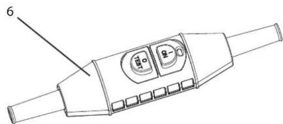
Line drawing of a spray gun with coiled hose and control panel (no text or symbols)TempSpray-H226/ TempSpray-H326
natural_image
Technical line drawing of a mechanical power spool with coiled cable and motor (no text or symbols)TEMPSPRAY H126, H226, H326

9 REPARATUREN AM GERÄT 15
1.2 EXPLOSIONSSCHUTZ

Gefahr
TempSpray - H326 / -H226
3.3 TRANSPORT
natural_image
Technical line drawing of a mechanical pump cart with hoses and wheels, no text or symbols present3.4 TECHNISCHE DATEN TEMPSPRAY-H326
Spannung : 230 Volt \~, 50 - 60 Hz
4.3 EINSCHALTEN
9 REPARATUREN AM GERÄT

9.2 TEMPSPRAY-H126
Zubehörbild
10.3 ERSATZTEILLISTE TEMPSPRAY-H326/-H226
10.4 ERSATZTEILLISTE HEIZSCHLAUCH TEMPSPRAY-H326 / -H226
| POS. | BESTELL-NR BENENNUNG | |
| 1 | 2312 | 111 Litze braun (2) |
| 2 | 2313 | 390 Hülse (2) |
| 3 | 9900 | 325 Zylinderschraube M6x16 DIN 912 (4) |
| 4 | 2311 | 137 Druckplatte |
| 5 | 9984 | 506 9984 515 |
| 6 | 3054 | 990 Aderendhülse (2) |
| 7 | 2312 | 199 Isolierschlauch (2) |
| 8 | 2312 | 110 Litze grün/gelb |
| 9 | 2311 | 136 Verschraubung Sensor |
| 10 | 9900 | 392 Zylinderschraube M4x6 DIN 912 (4) |
| 11 | 9922 | 101 |
| 12 | 2308 | 061 Temperatursensor NTC |
www.wagner-group.com/profi-guarantee.
Division Professional Finishing
Otto Lilienthal Strasse 18
88677 Markdorf
Translation of the original operating instructions
WARNING!
Attention, danger of injury by injection!
Airless units develop extremely high spray pressures.
  Danger Danger | |
| 1 | The grounding of the heating-hose has to be ensured at all times.Attention must be given during operation with inflammable materials-> the device is not explosion-proof. |
| 2 | The following points are to be observed in accordance with the operating manual before every start-up:Faulty units may not be used.Ensure earthing:Check the permissible operating pressure of the high-pressure hose and spray gun.Check all the connecting parts for leaksUse personal protective equipment (e.g. gloves, if necessary). |
| 3 | Instructions for regular cleaning and maintenance of the unit are to be observed strictly.Observe the following rules before any work on the unit and at every working break:Relieve the pressure from the spray gun and high-pressure hose.Secure a Wagner spray gun with the securing lever at the trigger guardSwitch the unit off. |
Ensure safety!
Table of Contents
1 SAFETY REGULATIONS FOR AIRLESS SPRAYING 31
1.1 Flash point 31
1.2 Explosion protection 31
1.3 Danger of explosion and fire from sources of ignition during spraying work ____ 31
1.4 Electric charge (spark and flame formation) ____ 31
1.5 Earthing of the object 31
1.6 Protective earthing of the heating hose ____ 31
1.7 Use of units on building sites and workshops ____ 31
1.8 High pressure hose 31
1.9 Personal protection while hot spraying ____ 32
1.10 Cleaning the unit 32
1.11 Cleaning the unit with solvents 32
1.12 Work or repairs at the electrical equipment ____ 32
1.13 Work at electrical components 32
1.14 Max. operating pressure 32
1.15 Setting 32
2 OVERVIEW OF APPLICATION 33
2.1 Range of application 33
2.2 Coating material 33
2.2.1 Coating materials with sharp-edged additional materials ____ 33
3 DESCRIPTION OF UNIT 33
3.1 General function of the devices 33
3.2 Explanatory diagram 34
3.3 Transport 35
3.4 Technical data TempSpray-H326 36
3.5 Technical data TempSpray-H226 36
3.6 Technical data TempSpray-H126 37
4 STARTUP 38
4.1 TempSpray-H326 and TempSpray-H226 ____ 38
4.1.1 Connection to the mains network 38
4.1.2 Cleaning preserving agent when starting-up of operation initially ____ 38
4.2 TempSpray-H126 39
4.2.1 Connection to the mains network ____ 39
4.2.2 Cleaning preserving agent when starting-up of operation initially ____ 39
4.3 Switch-on 40
4.4 Temperature adjustment 40
5 HANDLING THE HIGH-PRESSURE HOSE ____ 41
6 INTERRUPTION OF WORK 41
7 CLEANING THE DEVICE 41
7.1 Cleaning the unit from the outside 41
8 SERVICING 42
8.1 General servicing 42
9.1 TempSpray-H326 and TempSpray-H226
Changing the power cord ____ 42
9.2 TempSpray-H126
Changing the power cord ____ 43
9.3 Insulation test with 1000 volts DC during device inspection by Service ____ 43
9.4 Eliminating faults 44
9.5 Circuit diagram TempSpray-H326 / -H226 ____ 45
9.6 Circuit diagram TempSpray-H126 46
10.1 Accessories TempSpray 47
10.2 Overview of TempSpray versions and spray packs _ 47
10.3 Spare parts list TempSpray-H326 / -H226 ____ 48
10.4 Spare parts list heating hose
TempSpray-H326 / -H226 ____ 50
10.5 Spare parts list TempSpray-H126 51
10.6 Spare parts list heating hose TempSpray-H126 52
Testing of the unit 53
Important information on product liability 53
Note on disposal 53
Guarantee declaration 53
CE - declaration 54
European service network 112
9 REPAIRS AT THE UNIT 42
10 SPARE PARTS AND ACCESSORIES 47
1 SAFETY REGULATIONS FOR AIRLESS SPRAYING
All local safety regulations in force must be observed.
The following sources are just a sample of those containing safety requirements for Airless spraying.
a) The European Standard „Spray equipment for coating materials – safety regulations „ (EN 1953: 1998).
The safety regulations of the manufacturer of the Airless unit are to be observed in order to ensure safe handling of the Airless high-pressure spraying unit.
Observe the following additional safety instructions during operation with these specified heating-hoses:
1.1 FLASH POINT

Only spray coating materials with a flash point of at least 5 kelvin higher than the set temperature (minimum flash point is 21°C).
The flash point is the lowest temperature at which vapors develop from the coating material. These vapors are sufficient to form an inflammable mixture over the air above the coating material.
1.2 EXPLOSION PROTECTION

Do not use the unit in work places which are covered by the explosion protection regulations.
The unit is not designed to be explosion protected.
1.3 DANGER OF EXPLOSION AND FIRE FROM SOURCES OF IGNITION DURING SPRAYING WORK

There must be no sources of ignition such as, for example, open fires, lit cigarettes, cigars or tobacco pipes, sparks, glowing wires, hot surfaces, etc. in the vicinity.
1.4 ELECTRIC CHARGE (SPARK AND FLAME FORMATION)

Due to the flow speed of the coating material in the hose, there is the possibility of electrostatic charging at the equipment.
These can involve spark or flame formation at discharge. Therefore it is necessary that the Airless-unit is earthed according to directions at all time.
Electrostatic charging of spray guns and the high-pressure hose is discharged through the high-pressure hose. For this reason the electric resistance between the connections of the high-pressure hose must be equal or lower than 1 MΩ.
The resistance of the TempSpray - H126 must be equal or lower than 2 Ohm.
1.5 EARTHING OF THE OBJECT
The object to be coated must be earthed.
(Building walls are usually earthed naturally)
1.6 PROTECTIVE EARTHING OF THE HEATING HOSE
In case of defect (of the heating conductor), protection against an electric shock is secured by the protective earthing of the heating hose. This earthing is implemented by the electric supply to a shock proof socket

Be sure that the grounding of the shock proof socket, to which the heating-hose will be connected, is installed as prescribed and functioning.
1.7 USE OF UNITS ON BUILDING SITES AND WORKSHOPS
The unit may only be connected to the mains network via a special feeding point with a residual-current device with INF ≤ 30 mA.

Wagner's accessories program also includes a mobile operator protection device for the electronic supply, which can also be used with other electronical equipment.
1.8 HIGH PRESSURE HOSE

Attention, danger of injury by injection! Wear and tear and kinks as well as usage that is not appropriate to the purpose of the device can cause leakages to form in the high-pressure hose. Liquid can be injected into the skin through a leakage.
- High-pressure hoses must be checked thoroughly before they are used.
- Replace any damaged high-pressure hose immediately.
- Never repair defective high-pressure hoses yourself!
- Avoid sharp bends and folds: the smallest bending radius is about 20 cm.
- Do not drive over the high-pressure hose. Protect against sharp objects and edges.
- Never pull on the high-pressure hose to move the device.
- Do not twist the high-pressure hose.
- Do not put the high-pressure hose into solvents. Use only
a wet cloth to wipe down the outside of the hose.
- Lay the high-pressure hose in such a way as to ensure that it cannot be tripped over.

Only use WAGNER original-high-pressure hoses in order to ensure functionality, safety and durability.
1.9 PERSONAL PROTECTION WHILE HOT SPRAYING

During all spraying with a temperature-setting of more than 43^ C (display on the control panel starts blinking) take adequate safety measures against combustion.
-> Wear protective gloves.
Attention: The high-pressure hose and the hose whip are heated, too!
Use of a plastic coated spray gun is recommended.
1.10 CLEANING THE UNIT

Danger of short-circuits caused by water in-gression!
Never spray down the unit with high-pressure or high-pressure steam cleaners.
1.11 CLEANING THE UNIT WITH SOLVENTS

When cleaning the unit with solvents, the heating of the heating hose has to be switched off, because an explosive gas/air-mixture can emerge in the hose. The solvent should never be sprayed or pumped back into a container with a small opening (bunghole). An explosive gas/air mixture can arise. The container must be earthed.
1.12 WORK OR REPAIRS AT THE ELECTRICAL EQUIPMENT
These may only be carried out by a skilled electrician. No liability is assumed for incorrect installation.
1.13 WORK AT ELECTRICAL COMPONENTS
Unplug the power plug from the outlet before carrying out any repair work.
1.14 MAX. OPERATING PRESSURE
The permissible operating pressure for the spray gun, spray gun accessories, unit accessories and high-pressure hose must not fall short of the maximum operating pressure of 25 MPa (250 bar or 3625 psi).
1.15 SETTING
TempSpray-H326 and TempSpray-H226:
Position the heating-hose drum close to the spray-painting device, without causing a risk of stumbling.
Do not use the heating-hose drum, if the power cord is defect.
TempSpray-H126:
Assemble the governor housing to an adequate and sufficiently fixed device connection.
Don't use the heating-hose, if the power cord is defect.
2 OVERVIEW OF APPLICATION
2.1 RANGE OF APPLICATION
The heating-hoses TempSpray-H326, TempSpray-H226 and TempSpray-H126 are designed for all established Airless paint-spraying devices, whose operating pressure is below the rated pressure of the heating-hoses.

With some electronically controlled Airless-devices, the operation of a TempSpray-H126 can lead to malfunctions. To avoid this, mount a shock absorber (e.g. a 15m meter long textile reinforced high-pressure hose) between the device and the heating hose.
With the heating-hoses, mainly water-based colours can be heated from 20°C to 60°C, to improve the spraying on the Airless-nozzle.
Thereby it is possible to improve both spray result and material consumption. This depends on the used material and the calibration of the parameters. The heating-hoses can be used both in workshops and on construction sites.
Due to the cross-section and the operation length, the TempSpray-H326 is adapted well for high-viscosity materials outdoors.
Due to its shorter hose, TempSpray -H226 is recommended for smaller objects and indoor work.
Both hoses are qualified for the operation of an inside-fed paint roller.
In the lacquer sector TempSpray -H326, -H226 and -H126 can be used, but pay attention to the safety instructions, especially in reference to explosion protection.
The TempSpray-H126 is specifically conceived for lacquer work. Its minor hose-section raises the handling and reduces the needed volume of lacquer to fill the hose.
The TempSpray-H126 is not capable for high-viscosity materials and big nozzles.
TempSpray heated hoses must not be used in areas that come under the Explosion Protection Ordinance.
2.2 COATING MATERIAL
Diluting lacquers and paints or those containing solvents, two-component coating materials, dispersion and latex paints.
No other materials should be used for spraying without WAGNER's approval.
In particular, airless spray putty, high-viscosity coating substances such as, e.g. roof coatings and corrosion protection
No other materials should be used for spraying without WAGNER's approval.

Pay attention to the Airless quality of the coating materials to be processed.

Regard the directions from the colour-manufacturer (technical data sheets of the colours):

Some colours will be destroyed, if they are heated over a certain level. Some colours attain a high viscosity, thus they can damage the heating wire in the hose.
The TempSpray-H326/H226 can be used for coating materials with a viscosity up to 25,000 mPas.
The heating-hose TempSpray-H126 can be used for coating materials with a viscosity up to 5,000 mPas.
2.2.1 COATING MATERIALS WITH SHARP-EDGED ADDITIONAL MATERIALS
These particles have a strong wear and tear effect on valves and tips, but also on the heating hose and spray gun. This impairs the durability of these wearing parts considerably.
3 DESCRIPTION OF UNIT
3.1 GENERAL FUNCTION OF THE DEVICES
For a better understanding of the function see the technical configuration below:
All 3 heating-hoses are heated via an electric conductor, which is located directly in the colour-flow in the inside of the hose. An electric current flows trough the heating conductor, which is thereby heated up. Thereupon it changes its electrical resistance proportional to its temperature. The electronic system in the governor housing measures this resistance constantly and calculates the temperature of the heating conductor out of it, without any further sensor. The control electronics adapts the current flow so that the set temperature is kept constant.
The output of the heating-hoses is limited. If the volume flow rate is too high (nozzle too big) or the temperature of the materials before processing is too low, the results may vary. Of course the surrounding air temperature has an effect on the heating-ability of the heating-hoses, too.
Calculated values for the orientation can be found in the specification of each heating-hose.
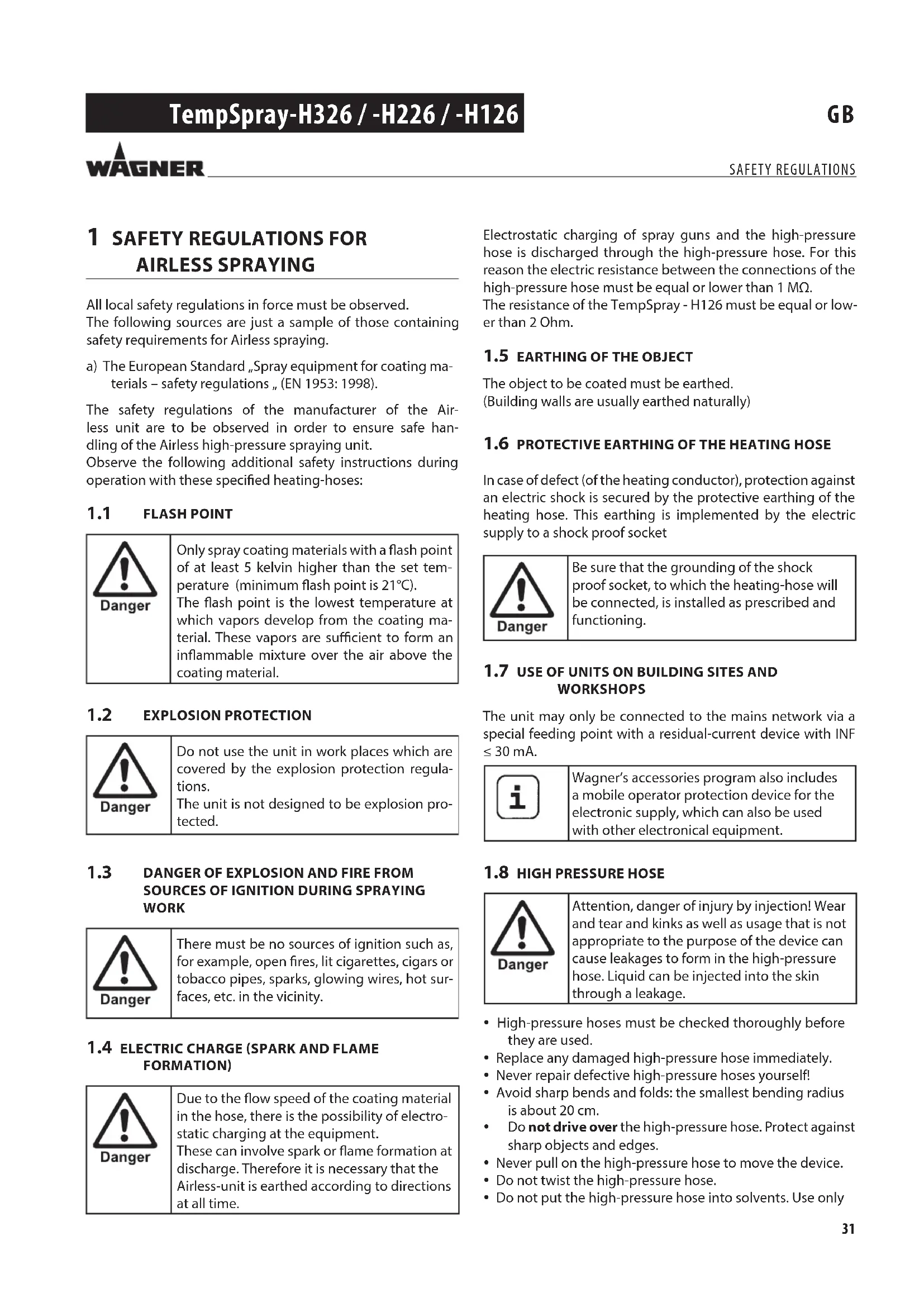
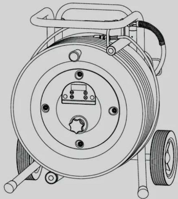
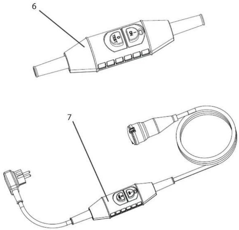
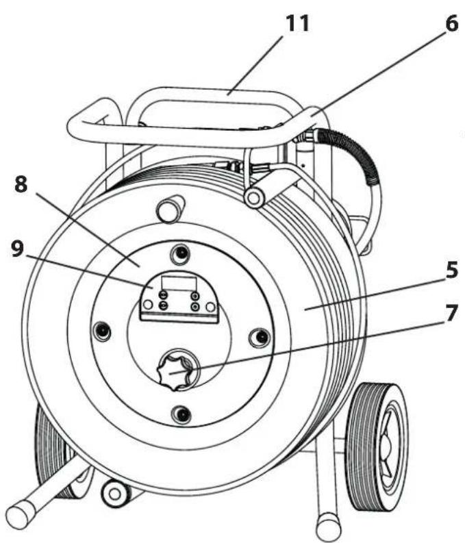
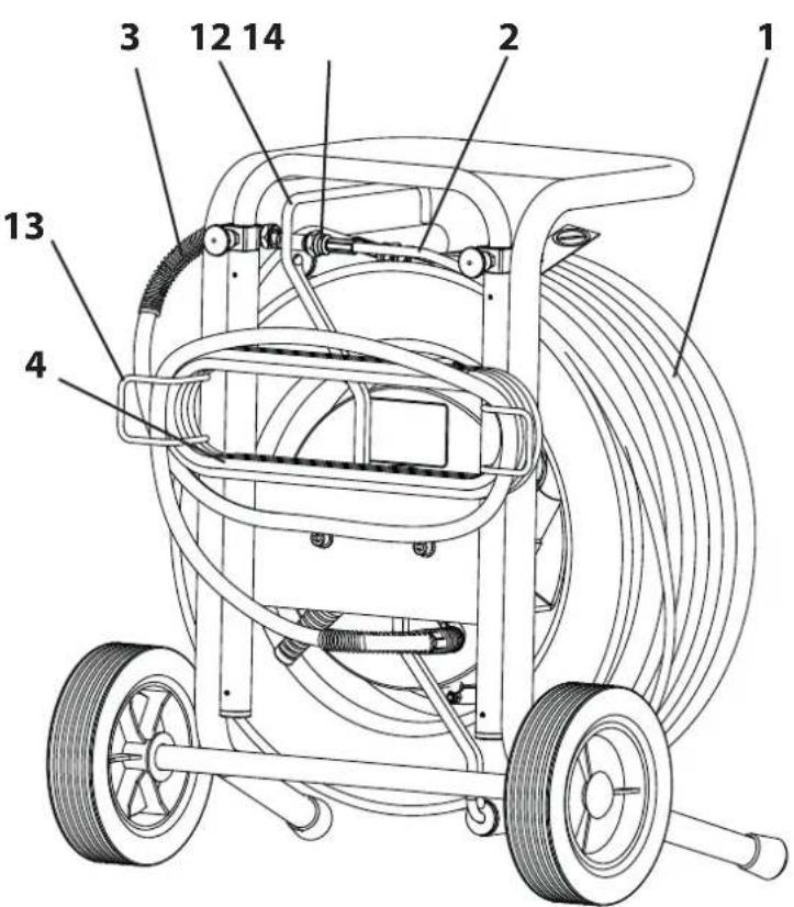
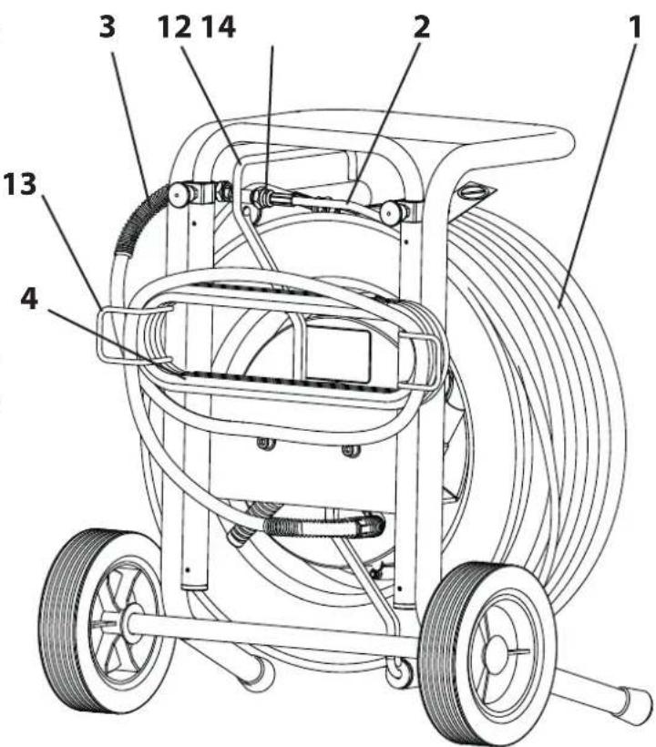
3.2 EXPLANATORY DIAGRAM
1 HP hose
2 Hose whip
3 Connecting hose
4 Power cord
5 Hose drum
6 Frame
7 Lock wheel
8 Governor housing
9 Control panel with display
10 Screw connexion (TempSpray-H126)
11 Telescopic handle
12 Hose guide with roller
13 Cable holder
14 Park fitting for fixing the hose during transport
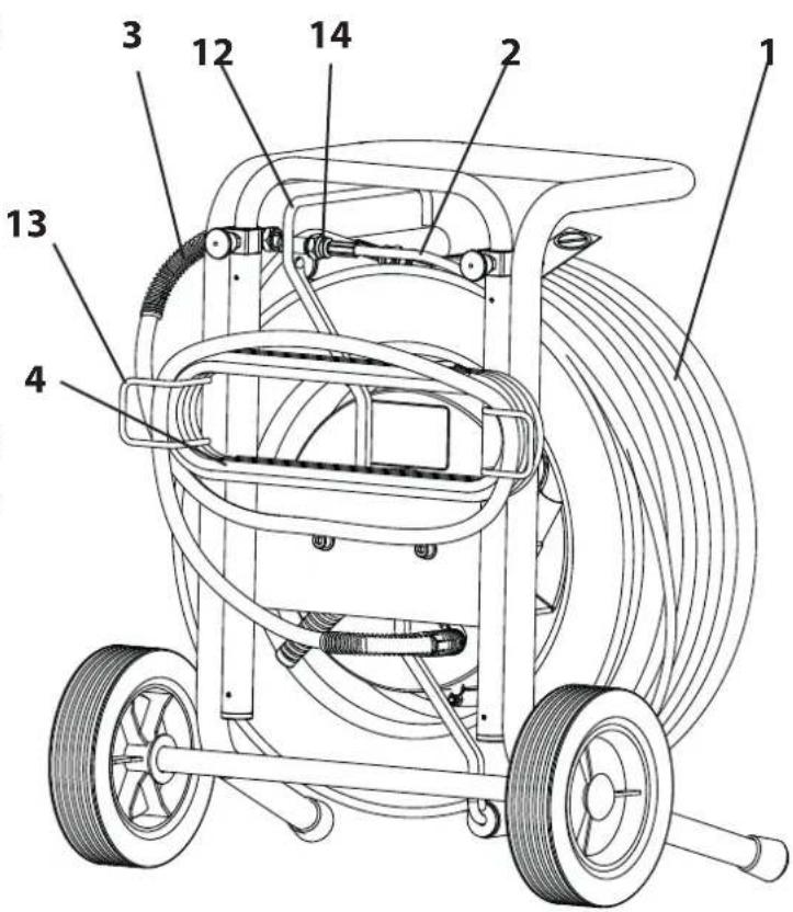
TempSpray - H326 / -H226
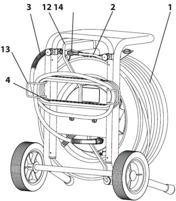
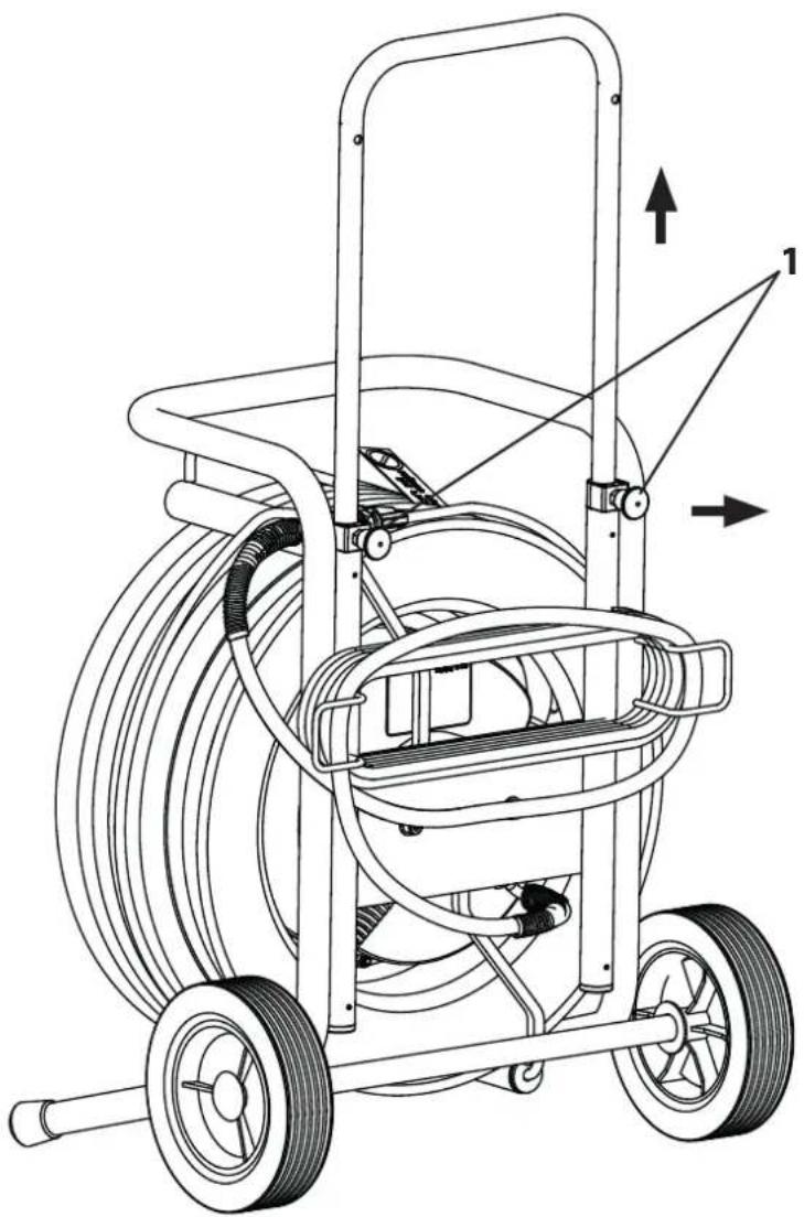
3.3 TRANSPORT
TempSpray-H326 and TempSpray-H226:
Roll up the high-pressure hose and fix to the hose guide park fitting. Coil connecting hose over the cable holder and connect it to the park fitting as well. Roll up the mains connection cable onto the cable holder.
Pull the locking pins (Item 1) on both sides of shaft. The locking pins can be arrested by a small turn (left or right). Pull the shaft out and deblock the locking pins. A light pull or push will help to lock the pins well.

Carry the device – don't throw it!
TempSpray-H126:
Roll up the high-pressure hose (rolldiameter greater than 20cm). Then roll up the power cord as well. The advice can be transported with the Airless-unit on which it is mounted (See details for transport of the Airless-unit).
natural_image
Technical line drawing of a mechanical power pump with hoses and wheels (no text or symbols)3.4 TECHNICAL DATA TEMPSPRAY-H326
Voltage: 230 Volt \~, 50 - 60 Hz
Fuses : 16 A
Power cord : 6 m long, 3x1.5 mm ^2
Max. current consumption : 5.2 A
Degree of protection : IP 54
Max. heating output : 1.1 kW
Max. operating pressure : 25 MPa (250 bar)
Hose : DN10-30m-textile reinforced
Inner diameter : 10 mm
Length: 30m
Fitting : 3/8" NPSM
Hose whip : DN5-1m-steel reinforced
Inner diameter : 5 mm
Length : 1 m
Fitting : 1/4" NPSM
Connecting hose : DN6-1.6m-textile reinforced
Inner diameter : 6 mm
Length : 1.6 m
Fitting : 1/4" NPSM
Max. viscosity of the
coating material :: 25,000 mPas
Adjustable temperature range: 20°C - 60°C
Dead weight : 16.8 kg
Performance :
Max. nozzle size :
(Continuous operation with water) 0.015"; more than 50°C -> 0.013"
Max. nozzle size:
(Continuous operation 0.023"; with emulsion paint) more than 50°C -> 0.019"
* based on surrounding and material temperature of 20°C. During intervallic operation (gun opened/closed) bigger nozzles can be used.
3.5 TECHNICAL DATA TEMPSPRAY-H226
Voltage : 230 Volt \~, 50 - 60 Hz
Fuses : 16 A
Power cord : 6 m long, 3x1.5 mm ^2
Max. current consumption : 5.9 A
Degree of protection :: IP 54
Max. heating output: 1.3 kW
Max. operating pressure : 25 MPa (250 bar)
Hose : DN10-15m-textile reinforced
Inner diameter : 10 mm
Length: 15 m
Fitting : 3/8" NPSM
Hose whip : DN5-1m-steel reinforced
Inner diameter : 5 mm
Length: 1 m
Fitting : 1/4" NPSM
Connecting hose : DN6-1.6m-texile reinforced
Inner diameter : 6 mm
Length : 1.6 m
Fitting : 1/4" NPSM
Max. viscosity of the
coating material: 25,000 mPas
Adjustable temperature range: 20°C - 60°C
Dead weight: 13.2 kg
Performance :
Max. nozzle size :
(Continuous operation with water) 0.013"; more than 50°C -> 0.011"
Max. nozzle size :
(Continuous operation 0.021"; with emulsion paint) more than 50°C -> 0.019"
* based on surrounding and material temperature of 20°C. During intervallic operation (gun opened/closed) bigger nozzles can be used.
3.6 TECHNICAL DATA TEMPSPRAY-H126
Voltage : 230 Volt \~, 50 - 60 Hz
Fuses : 16 A
Unit connecting line : 4 m long, 3x1.5 mm ^2
Max. current consumption : 2.6 A
Degree of protection : IP 54
Max. heating output : 0.6 kW
Max. operating pressure : 25 MPa (250 bar)
Hose : DN6-10m-steel reinforced
Inner diameter : 6 mm
Length : 10 m
Fitting : 1/4" NPSM
screw connection to the
device 1/4" NPSM
Max. viscosity of the
coating material : 5,000 mPas
Adjustable temperature range: 20°C - 60°C
Dead weight : 3.2 kg
Performance :
Max. nozzle size :
(Continuous operation 0.011";
with water) more than 50^ C -> 0.009"
Max. nozzle size :
(Continuous operation 0.015";
with emulsion paint) more than 50^ C -> 0.013"
* based on surrounding and material temperature of 20°C.
During intervallic operation (gun opened/closed) bigger nozzles can be used.
4 STARTUP
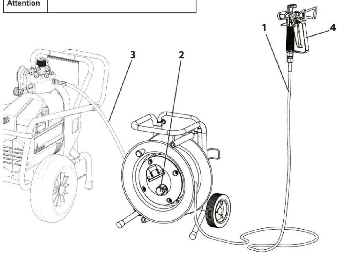
4.1 TEMPSPRAY-H326 AND TEMPSPRAY-H226
- Place hose drum close to the Airless-unit.
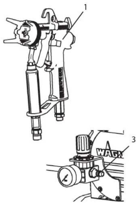
- Release hose whip (1) from frame and roll up the high-pressure hose. Also release the lock-advice (2) and lock it again after rolling the hose up.
- Release connecting hose and connect it to the hose adapter of the airless-unit.
- Mount spray gun (4) to the hose whip.
- Tighten all coupling nuts strongly, in order that no coating material can leak.
- Mount the nozzle holder with the chosen nozzle on the spray gun, position it and tighten it well (See manual of the spray gun/ nozzle holder).
| Attention | For safety reasons never use the heating-hose without the steal-armoured hose whip, if working with a spray gun. |
| Attention | Counter with a wrench, if you unscrew the high-pressure hose from the hose connector. |
4.1.1 CONNECTION TO THE MAINS NETWORK
| Attention | Connection must always be carried out via an appropriately grounded safety outlet with residual-current-operated circuit-breaker. |
Before connecting the unit to the mains supply, ensure that the line voltage matches that specified on the unit's rating plate.
4.1.2 CLEANING PRESERVING AGENT WHEN STARTING-UP OF OPERATION INITIALLY
Rinse the heating hose with a suitable cleaning agent (recommendation: water) at a low pressure setting. Therefore use a spray gun without nozzle and spray into an open box.
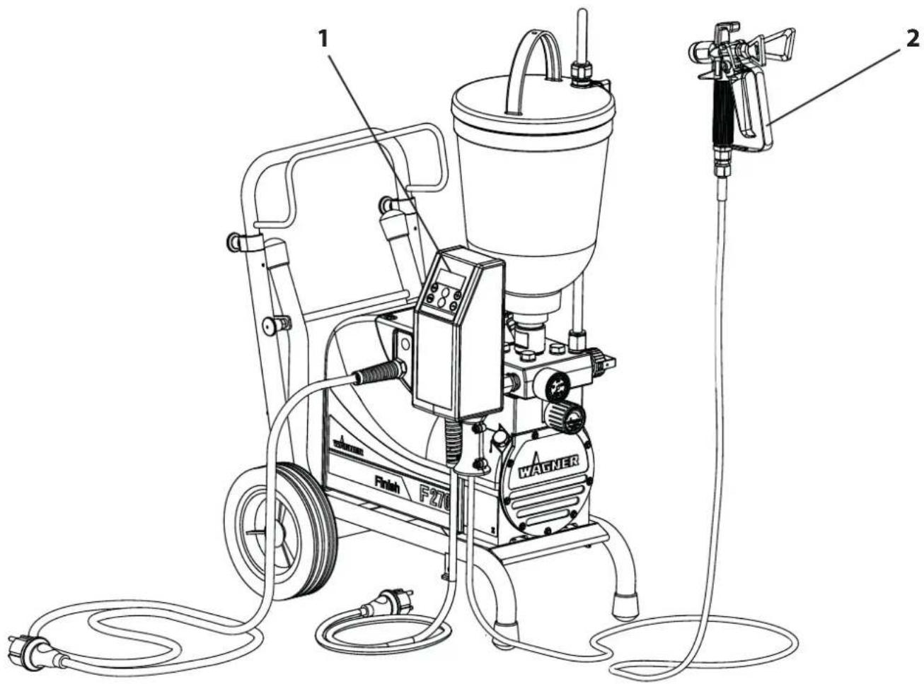
4.2 TEMPSPRAY-H126
- Mount the governor housing (1) to the hose connector of the airless-unit, thereby arrange the housing in a way that you can reach the control panel easily and no important accesses are barred.
- Roll up the high-pressure hose.
- Mount spray gun (2) to the high-pressure hose.
- Tighten all coupling nuts well, in order that no coating material can leak.
- Mount the nozzle holder with the chosen nozzle on the spray gun, position it and tighten it well (See manual of the spray gun/ nozzle holder).
| Attention | Counter with a wrench, if you unscrew the high-pressure hose from the hose connector. |
4.2.1 CONNECTION TO THE MAINS NETWORK

Connection must always be carried out via an appropriately grounded safety outlet with residual-current-operated circuit-breaker.
Before connecting the unit to the mains supply, ensure that the line voltage matches that specified on the unit's rating plate.
4.2.2 CLEANING PRESERVING AGENT WHEN STARTING-UP OF OPERATION INITIALLY
Rinse the heating hose with a suitable cleaning agent (recommendation: water) at a low pressure setting. Therefore use a spray gun without nozzle and spray into an open box.
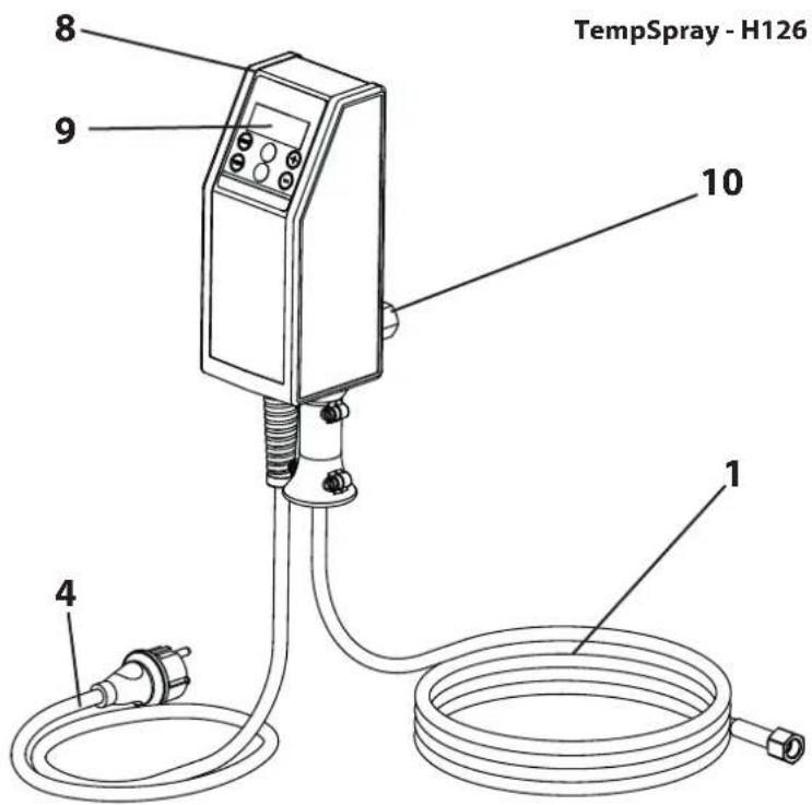
4.3 SWITCH-ON
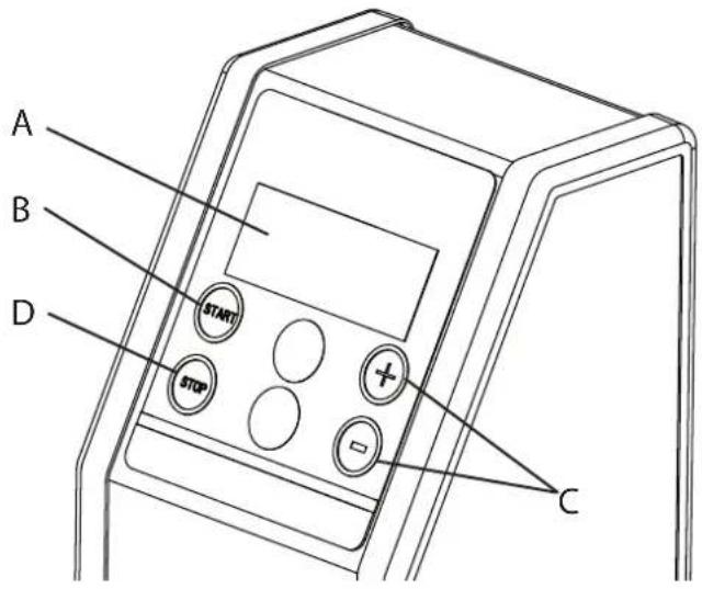
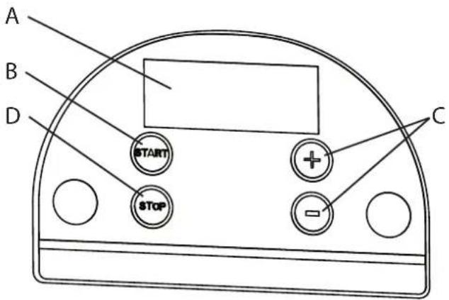
Connect the heat controller to the mains supply. OFF appears in the display window (A) to indicate operational readiness. Press the START button (B), to switch the heat controller on. The display window changes from OFF to the preset temperature of 40°C and the heating process begins.
 | While the material in the heated hose is being heated, a dot illuminates in front of the temperature display. As soon as this goes out, it will take another approx. 2 minutes until the material reaches the set temperature. |
 | If the dot illuminates again during the work cycle, the material in the hose is heated further, in order to keep the set temperature constant.If the illuminated dot no longer disappears and the spray result deteriorates, a smaller nozzle should be used for this material. |
TempSpray - H126
4.4 TEMPERATURE ADJUSTMENT
The Temperature can be raised or reduced in 1° steps by using the foil-buttons and (C) ^+ °C" flashes during adjustment). To set the temperature you adjusted, you have to push the set-button START (B) within 3 seconds, otherwise the heating control resets to the temperature that was used before. If you press on of the buttons and (C) constantly, the adjustment-speed raises. After confirming with START, "°C" illuminates constantly.
The adjustment range is from 20^ C to 60^ C. A change in every direction is always possible.
The heating can take a couple of minutes until the adjusted temperature is reached. This depends on the start temperature of the material and on the surrounding temperature. It is assumed that the heating time takes from 3 to 8 minutes.
| Attention | At temperature adjustments over 43°C, the display value starts blinking. This is a hint for possible danger of getting burnt. |
To switch the heat controller off again, press the STOP button (D). The selected temperature will be saved until the next start-up. However, if the power plug is removed, the heat controller will be reset to the default temperature of 40^ C upon restarting.
This happens to avoid an unintended overheating of an eventually damageable coating material.
TempSpray - H326 / -H226
5 HANDLING THE HIGH-PRESSURE HOSE
| Danger | Danger of injury through leaking high-pressure hose. Replace any damaged high-pressure hose immediately.Never repair defective high-pressure hoses yourself! |
| Attention | The high-pressure hose can't be removed from the hose reel or the controller housing.Never try to loosen the connection. |
The high-pressure hose is to be handled with care. Avoid sharp bends and folds: the smallest bending radius is about 20 cm. Do not drive over the high-pressure hose. Protect against sharp objects and edges.
Never pull on the high-pressure hose to move the device.
| Always unroll the high-pressure hose completely. | |
| When using the high-pressure hose while working on scaffolding, it is best to always guide the hose along the outside of the scaffolding. | |
| The risk of damage rises with the age of the high-pressure hose.Wagner recommends replacing high-pressure hoses after 6 years. | |
| Only use WAGNER original-high-pressure hoses with internal heating in order to ensure functionality, safety and durability. |
6 INTERRUPTION OF WORK
Release the pressure in the hose and switch off the heating during longer breaks.
| In using quick-drying or two-component coating materials, do not fail to rinse unit through with a suitable cleaning agent during the processing period.Important: The application life of the material can change as a result of heating. Therefore, please consult the material manufacturer. |
7 CLEANING THE DEVICE
A clean state is the best method of ensuring operation without problems. After you have finished spraying, clean the unit. Under no circumstances may coating material rests dry and harden in the unit.
Clean the device with an adequate detergent, after finishing the paint work.
The solvent used for cleaning (with a flash point over 21 °C) has to be adequate to the coating material.
| Danger | While cleaning with solvents (except water) -> always switch off heating. |
| Danger | Do not put the high-pressure hose into sol-vents. Use only a wet cloth to wipe down the outside of the hose. |
| Danger | The container must be earthed in case of coating materials which contain solvents (except water). |
| Danger | Caution! Do not pump or spray in container with small opening (bunghole)!See safety regulations.When cleaning without a nozzle, reduce the pressure to approx. 20 bar. |
| Warm water improves the cleaning effect in the case of water-dilutable coating materials. Therefore the heating can stay switched on. |
7.1 CLEANING THE UNIT FROM THE OUTSIDE
| Attention | First unplug the power plug from the outlet. Danger of short-circuits caused by water ingression! Never spray down the unit with high-pressure or high-pressure steam cleaners. |
Wipe unit externally with a piece of cloth, which has been immersed in a suitable cleaning agent.
8 SERVICING
8.1 GENERAL SERVICING
 | After the regulations of the Accident Prevention & Insurance Association an annual expert check is required- inclusive confirmation. |
 | You can servicing of the unit carried out by the Wagner Service. Favourable conditions can be agreed with a service agreement and/or maintenance packages. |
Minimum check before every startup:
- Check the high-pressure hose, power supply cable with plug for damage.
Inspect the high-pressure hose visually for any notches or bulges, in particular at the transition in the fittings.
Check at periodical intervals:
- The coupling nuts have to be clearly rotatable. The conductivity has to be less than 1 Mega Ohm (Tempspray-H326, Tempspray-H226) alternatively less than 2 Ohm (TempSpray-H126) over the whole length.
- Check the status of the heating conductor To do this, press and hold down the "START" and + buttons simultaneously, and also press the -button. If "0A" appears in the display, the heating conductor is ok. If a different value is shown for "A" (e.g. 5A), please contact Wagner Service to arrange for an insulation test.
- The isolation of the heating wire has to be tested with an insulation tester with at least 1000V.
| Attention | Have all the electric tests carried out by the Wagner Service. |
9 REPAIRS AT THE UNIT
| Attention | Switch the unit off.Before all repair work: Unplug the power plug from the outlet. |
Due to necessary custom tools repairs on the heating wire and the heating wire feed have to be done only by the Wagner-Service.
A replacement of the heating-hose should, due to its internal heating wire, only be done from the Wagner-Service as well. The hose whips of the TempSpray-H326 and TempSpray-H226 can be replaced without any problems.
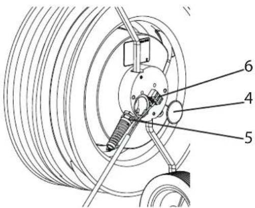
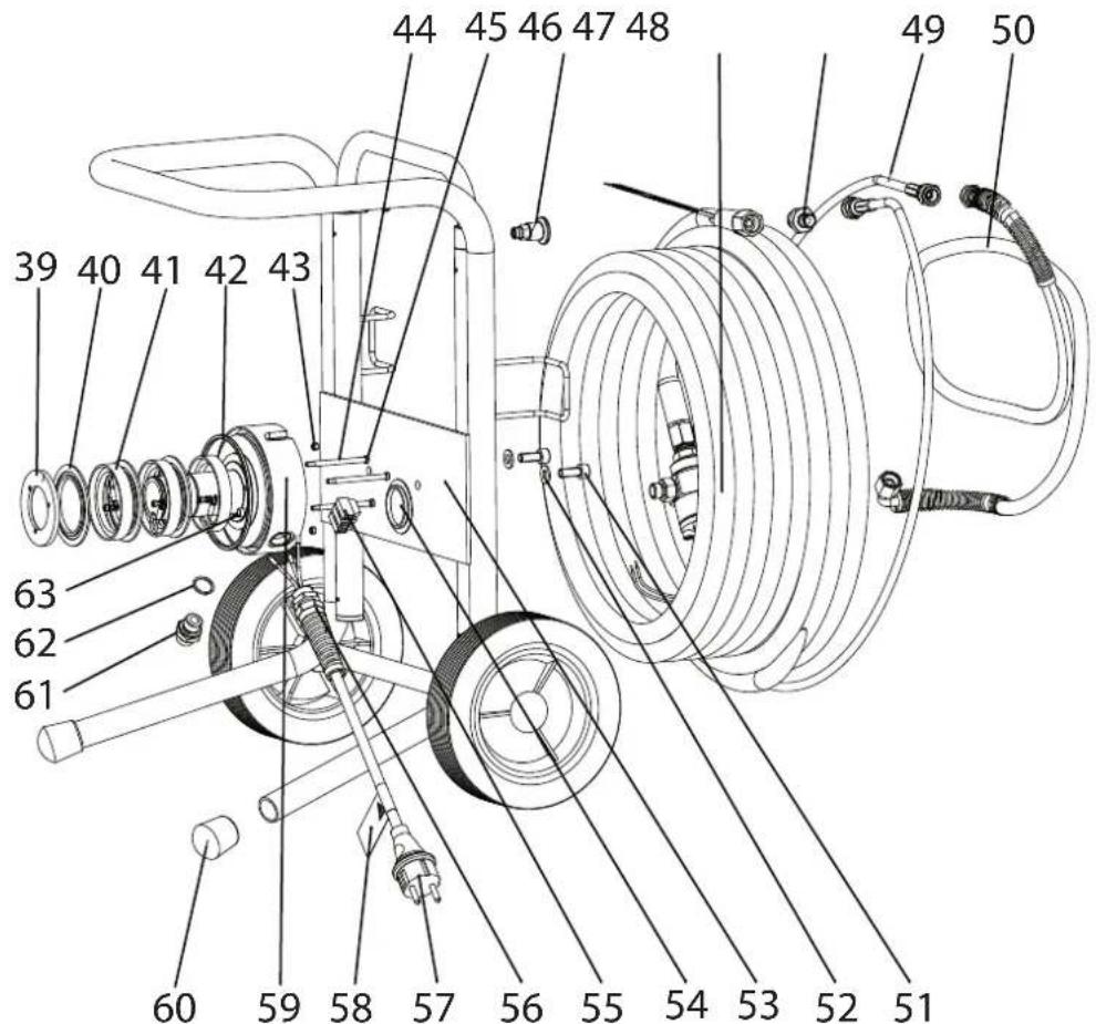
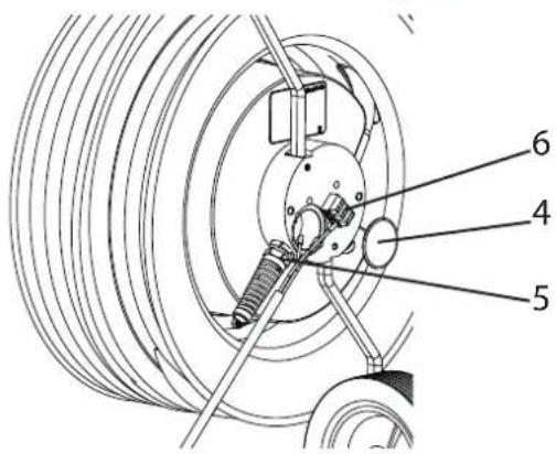
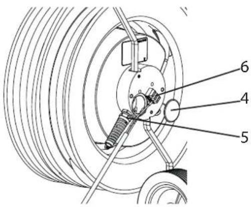
9.1 TEMPSPRAY-H326 AND TEMPSPRAY-H226 CHANGING THE POWER CORD
 Danger Danger | Switch the unit off.Before all repair work: Unplug the power plug from the outlet.Work or repairs at the electrical equipment may only be carried out by a skilled electrician. No liability is assumed for incorrect installation. |
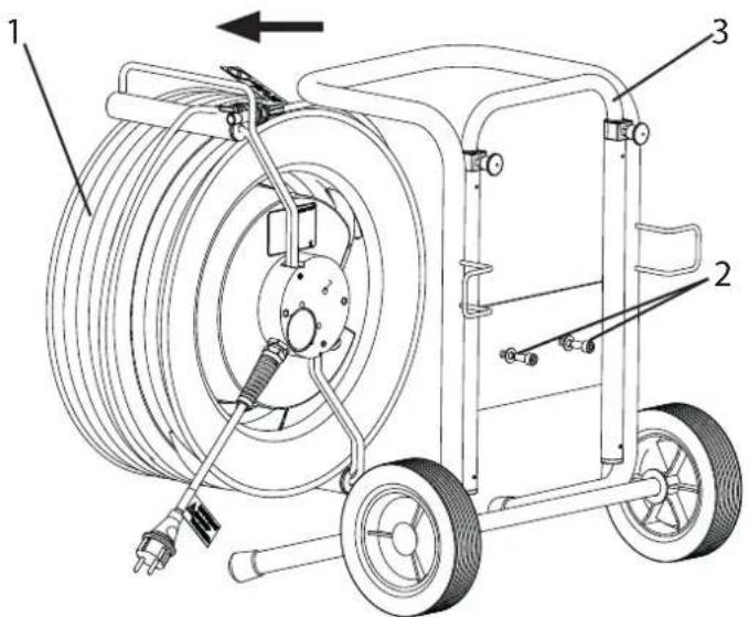
- Dismount the hose reel (1) by loosening the 2 screws (2) on the carriage (3).
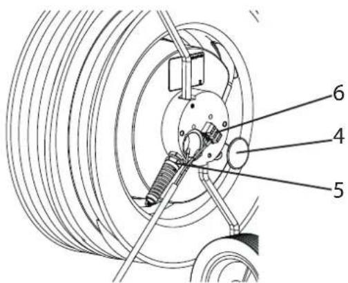
- Lever the plastic cover (4) off with a screwdriver.
- Release cable connexion (5). Disconnect the power cable from the terminal strip (6).
- Replace power cord (fix green-yellow conductor to PE-marked terminal).
(Only use a licensed power cord with the marking H07-RNF and with a splash water proof plug)
- Mount plastic covers carefully.
- Fix hose reel to the carriage again.
9.2 TEMPSPRAY-H126
CHANGING THE POWER CORD
| Danger | Switch the unit off.Before all repair work: Unplug the power plug from the outlet. |
- Release cable connexion (1).
- Remove protective covers (2).
- Loosen all four screws (3) and carefully remove left housing shell (4).
Attention: Control panel is connected to the right housing shell. - Release power cord (6) from the terminal (7) and replace it. (Only use a licensed power cord with the marking H07-RNF and with a splash water proof plug)
| Important information for installing the new mains connection cable:Lead mains cable conductor through the cable bushing (5) and return the latter to its position.Fix green-yellow conductor to PE-marked terminal. |
- Carefully mount housing shell (4) again.
Attention: Do not pinch any cables! The printed circuit board must be located in the guide rail, and the inserted cord must not twist.
- Fit screws (3) and protective covers (2) again.
9.3 INSULATION TEST WITH 1000 VOLTS DC DURING DEVICE INSPECTION BY SERVICE
| Danger | Switch the unit off.Before all repair work: Unplug the power plug from the outlet. |
- Open the housing as described in section 9.2.
- Detach one of the two heating conductors from the terminal and connect to a pole of the high-voltage tester.
- Connect the other pole of the tester to the ground of the leadthrough housing and perform test.
9.4 REMEDY IN CASE OF FAULTS
| DISPLAYED ERROR CODE POSSIBLE CAUSE MEASURES FOR ELIMINATING THE MALFUNCTION | ||
| Err0 Residual current exceeded (approx. 33mA) and relay cuts out:• Heating conductor insulation in hose damaged• Cable has come loose• Water has penetrated device | Please contact Wager Customer Service | |
| Err1 Electronics defective - no communication between the boards | Disconnect the device from the power supply.Wait approx. 30 seconds and switch it back on.If the error code is still displayed, contact Wagner Customer Service. | |
| Err2 Control board does not receive any feedback Disconnect the device from the power supply.Wait approx. 30 seconds and switch it back on.If the error code is still displayed, contact Wagner Customer Service. | ||
| Err3 Interface board does not receive any feedback/no information is received by the interface boardCables pinched in housing | Disconnect the device from the power supply.Wait approx. 30 seconds and switch it back on.If the error code is still displayed, contact Wagner Customer Service.Have a skilled electrician open the housing and check the cables. | |
| Err4 Heating resistance too large:Current flow in heating conductor is interruptedOvertemperature protection has actuated | Disconnect the device from the power supply.Wait approx. 30 seconds and switch it back on.If the error code is still displayed, contact Wagner Customer Service. | |
| Err5 Heating resistance too small:Short-circuit in heating wire | Disconnect the device from the power supply.Wait approx. 30 seconds and switch it back on.If the error code is still displayed, contact Wagner Customer Service. | |
| Temperature is displayed in °F instead of °C | Temperature display converted to Fahrenheit | Press „START“ and „—” simultaneously to convert the display to °C. |

In the case of all abovementioned errors, a task that has been started can still be finished with the TempSpray heating system switched off.
9.5 CIRCUIT DIAGRAM TEMPSPRAY-H326 / -H226
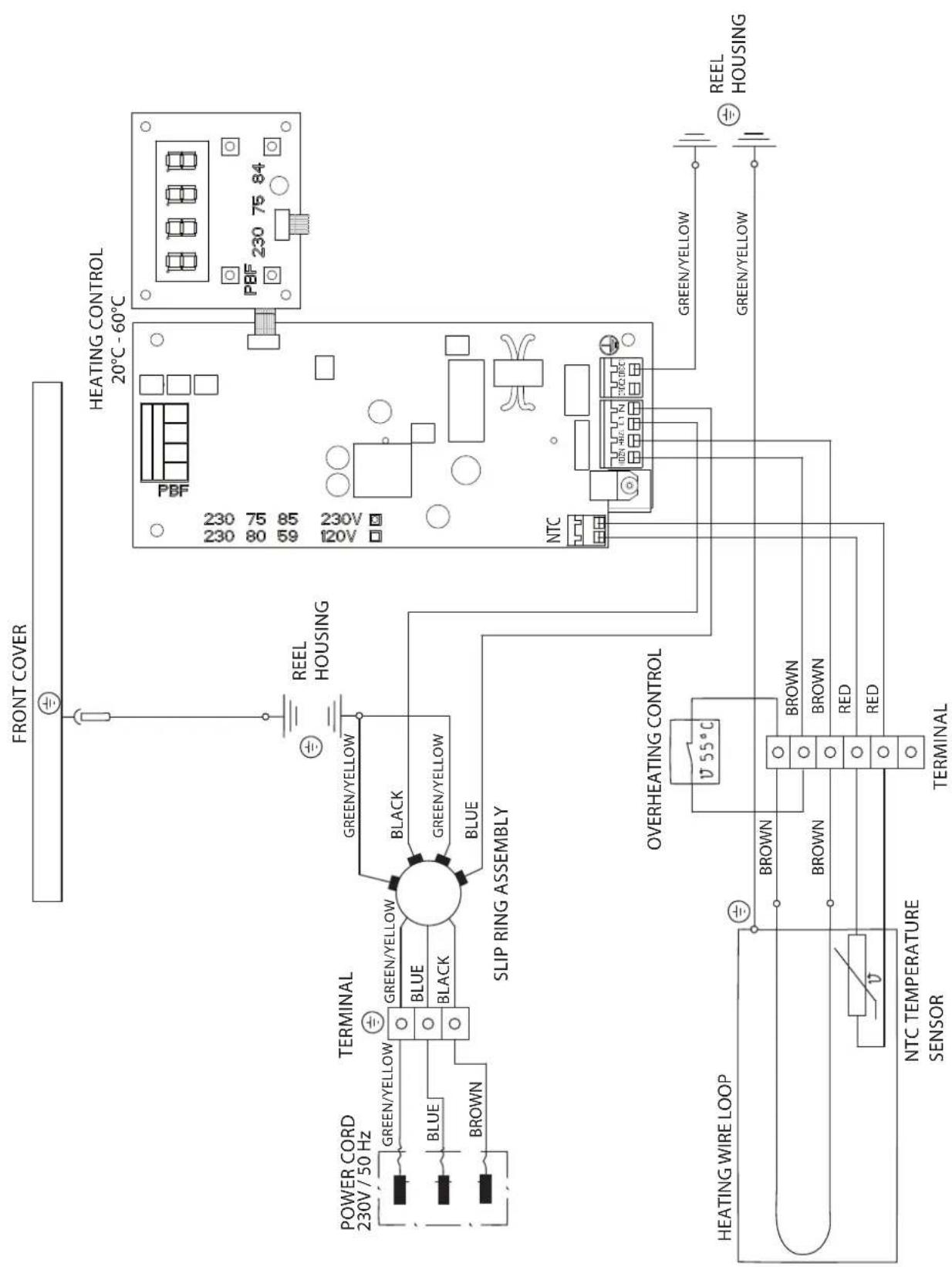
flowchart
graph TD
    A["FRONT COVER"] --> B["POWER CORD 230V / 50 Hz"]
    B --> C["GREEN/YELLOW"]
    B --> D["BLE"]
    B --> E["BROWN"]
    C --> F["GREEN/YELLOW"]
    D --> G["BLUE"]
    E --> H["BLCK"]
    F --> I["SLIP RING ASSEMBLY"]
    G --> I
    H --> I
    I --> J["GREEN/YELLOW"]
    I --> K["BLCK"]
    I --> L["GREEN/YELLOW"]
    I --> M["BLUE"]
    N["HEATING CONTROL 20°C - 60°C"] --> O["230 75 85 120V"]
    N --> P["PBF 230 75 84"]
    Q["OVERHEATING CONTROL"] --> R["NTC"]
    S["HEATING WIRE LOOP"] --> T["BROWN"]
    S --> U["BROWN"]
    S --> V["BROWN"]
    S --> W["BROWN"]
    S --> X["BROWN"]
    S --> Y["BROWN"]
    S --> Z["BROWN"]
    S --> AA["BROWN"]
    S --> AB["BROWN"]
    S --> AC["BROWN"]
    S --> AD["BROWN"]
    S --> AE["BROWN"]
    S --> AF["BROWN"]
    S --> AG["BROWN"]
    S --> AH["BROWN"]
    S --> AI["BROWN"]
    S --> AJ["BROWN"]
    S --> AK["BROWN"]
    S --> AL["BROWN"]
    S --> AM["BROWN"]
    S --> AN["BROWN"]
    S --> AO["BROWN"]
    S --> AP["BROWN"]
    S --> AQ["BROWN"]
    S --> AR["BROWN"]
    S --> AS["BROWN"]
    S --> AT["BROWN"]
    S --> AU["BROWN"]
    S --> AV["BROWN"]
    S --> AW["BROWN"]
    S --> AX["BROWN"]
    S --> AY["BROWN"]
    S --> AZ["BROWN"]
    S --> BA["BROWN"]
    S --> BB["BROWN"]
    S --> BC["BROWN"]
    S --> BD["BROWN"]
    S --> BE["BROWN"]
    S --> BF["BROWN"]
    S --> BG["BROWN"]
    S --> BH["BROWN"]
    S --> BI["BROWN"]
    S --> BJ["BROWN"]
    S --> BK["BROWN"]
    S --> BL["BROWN"]
    S --> BM["BROWN"]
    S --> BN["BROWN"]
    S --> BO["BROWN"]
    S --> BP["BROWN"]
    S --> BQ["BROWN"]
    S --> BR["BROWN"]
    S --> BS["BROWN"]
    S --> BT["BROWN"]
    S --> BU["BROWN"]
    S --> BV["BROWN"]
    S --> BW["BROWN"]
    S --> BX["BROWN"]
    S --> BY["BROWN"]
    S --> BZ["BROWN"]
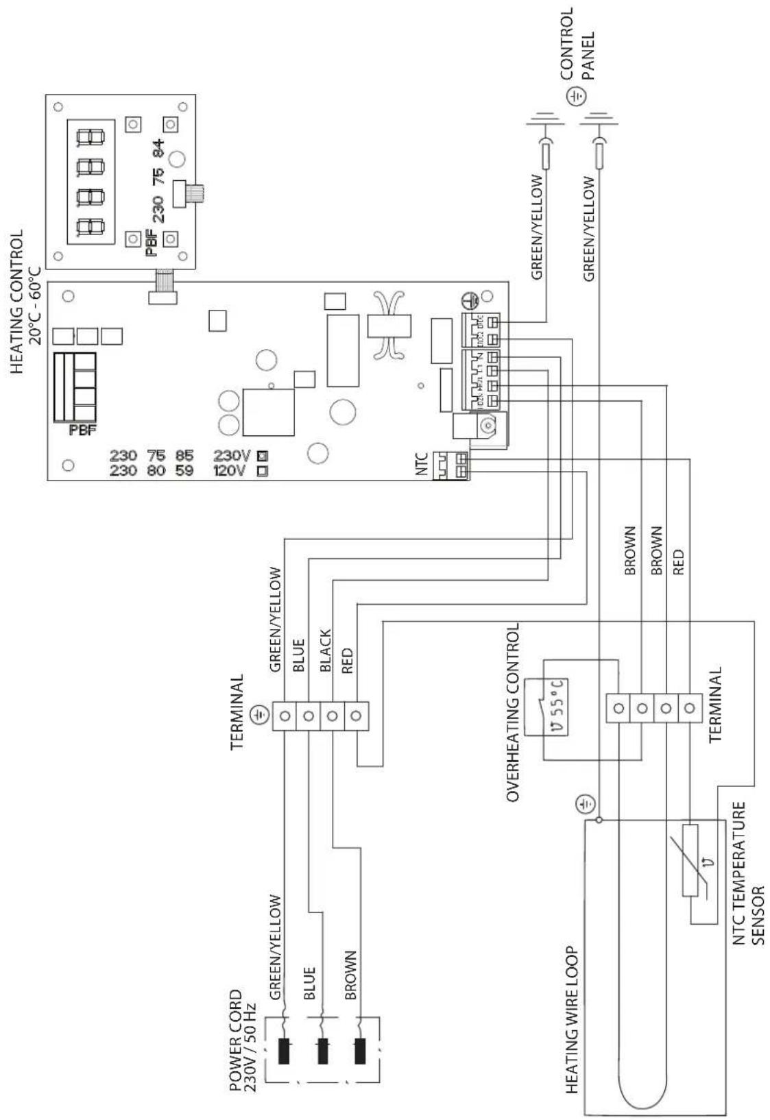
9.6 CIRCUIT DIAGRAM TEMPSPRAY-H126
10 SPARE PARTS AND ACCESSORIES
10.1 ACCESSORIES TEMPSPRAY
| POS. | ORTDER-NO DESIGNATION | |
| 1 2368 | 269 AirCoatspray gun AC 4500 Proincl. blue aircap (for water diluted materials), holder and nozzle | |
| 2 0344 | 905 Air hose | 10m for AirCoatspray gunwith TempSpray-H126 |
| 3 0252 | 910 AirCoat-regulator add-on kit forFinish 270/250 | |
| 4 0340 | 250 AirCoat-regulator add-on kit forSuperfinish units | |
| 5 0097 | 201 Connecting piece A: 1/4" |: M16x1.5 | |
| 6 9956 | 257 Personal protection switch (PRCD)230V / 16A (to be installed by a skilled electrician) | |
10.2 OVERVIEW OF TEMPSPRAY VERSIONS AND SPRAY PACKS
| ORTDER-NO DE | SIGNATION |
| 2311 659 Temp | pSpray -H126 230V |
| 2311 660 Temp | pSpray -H226 230V |
| 2311 661 Temp | pSpray -H326 230V |
| 2311 852 | Spraypacks:TempSpray -H126 |
| 2311 853 | TempSpray -H226 |
| 2311 854 | TempSpray -H326 |
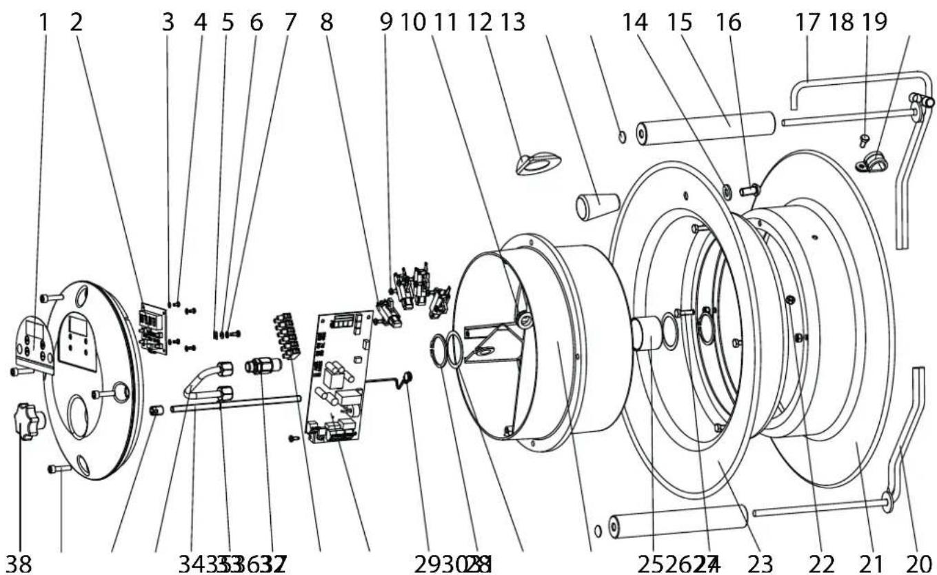
Spare parts diagram
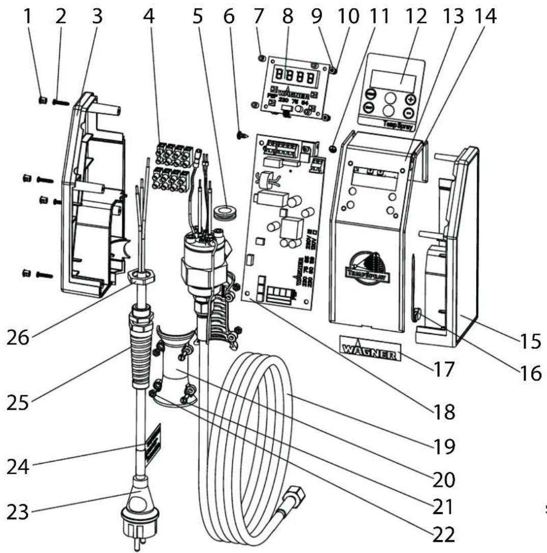
10.3 SPARE PARTS LIST TEMPSPRAY-H326 / -H226
| POS. | ORTDER-NO DESIGNATION | |
| 2311 | 664 Front cover assy.(pos. 1-7,33,34,36,38) | |
| 1 2311 | 069 Display | |
| 2 2307 | 584 Control panel heat controller | |
| 3 9920 | 123 Washer A3.2 DIN 126 (PA)(4) | |
| 4 9903 | 343 Thread-forming screwM3x6 DIN 7500 (4) | |
| 5 2309 | 735 Insert tongue | |
| 6 9920 | 104 Washer A4.2 DIN 125 (4) | |
| 7 9922 | 101 External tooth lock washer | |
| 8 2311 | 139 Carbon brush (4) | |
| 9 9903 | 322 Thread-forming screwM4x10 DIN 7500 (14) | |
| 10 9955 | 041 Cable bushing (2) | |
| 11 2312 | 445 Gasket | |
| 12 9990 | 374 Handle M10 | |
| 13 2312 | 295 Cap (2) | |
| 14 9920 | 106 Washer A10.5 DIN 125 | |
| 15 2312 | 297 Roller (2) | |
| 16 9903 | 347 Oval head screw M10x20 | |
| 17 2311 | 258 Hose guide | |
| 2315 901 Hose guide assy. (pos. 13,15,17) | ||
| 18 9900 | 106 Hexagon head screw M6x12 DIN933 | |
| 19 9990 | 232 Pipe clip | |
| 20 2312 | 296 Roller guide | |
| 2316 034 Roller guide assy. (pos. 13,15,20) | ||
| 21 2311 | 168 Rear reel shell | |
| 22 9910 | 204 Hexagon nut M6 DIN985(5) | |
| 23 2311 | 167 Front reel shell | |
| 24 9900 | 108 Hexagon head screw M6x20 DIN933 (4) | |
| 25 9994 | 962 Plain bearing | |
| 26 2311 | 002 Reel housing | |
| 27 9920 | 614 Shim ring (2) | |
| 28 9922 | 535 Circlip (2) | |
| 29 2311 | 171 Overheating control | |
| 30 2307 | 585 Heat controller for 230V control unit | |
| 31 2306 | 244 Terminal strip (6-way) | |
| 32 2311 | 150 Swivel joint assy. | |
| 33 9921 | 902 Retaining washer D6 DIN 6799 | |
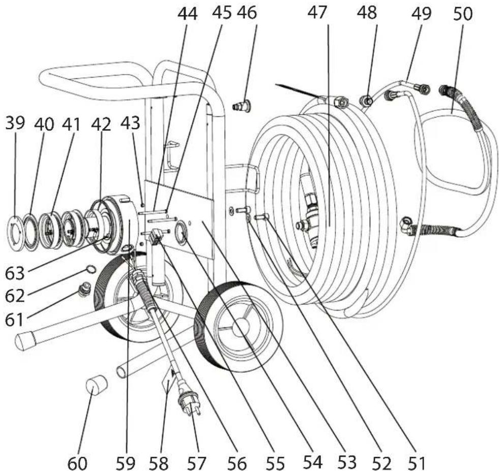
| POS. | RTDER-NO DESIGNATION | |
| 34 231 | 1 153 Threaded rod | |
| 35 231 | 1 148 Tube assy. | |
| 36 990 | 1 319 Threaded insert | |
| 37 990 | 06 003 Thread-forming screwM6x25 DIN 7500 (4) | |
| 38 231 | 2 233 Star grip | |
| 39 231 | 1 144 End ring | |
| 40 231 | 1 143 Insulating ferrule (3) | |
| 41 231 | 1 142 Slip ring (3) | |
| 42 230 | 9 732 Felt sealing strip | |
| 43 990 | 1 114 Setscrew M5x6 DIN 916 (2) | |
| 44 230 | 9 733 Heatshrink sleeving (3) | |
| 45 990 | 00 743 Socket head cap screw M4x60 DIN 84A (3) | |
| 46 025 | 2 455 Mini raster | |
| 47 231 | 11 6562311 657 | Heating hose assy. (H226)Heating hose assy. (H326) |
| 48 036 | 7 561 Double-ended union | |
| 49 998 | 4 458 Hose whip | |
| 50 998 | 4 590 Hose whip assy. | |
| 51 990 | 0 318 Socket head cap screwM8x20 DIN 912 (2) | |
| 52 992 | 0 102 Washer (2) | |
| 53 231 | 1 248 Hose reel complete | |
| 54 231 | 2 294 Cap | |
| 55 995 | 0 212 Terminal strip (3-way) | |
| 56 995 | 2 685 Cable coupling with antikink spiral | |
| 57 026 | 1 352 Power cord assy. | |
| 58 034 | 4 425 Power cable adhesive label | |
| 59 231 | 1 145 Bearing | |
| 2315 770 Bearing assy. (pos. 39-45,54-59,61-63) | ||
| 60 999 | 0 866 Rubber cap (2) | |
| 61 034 | 1 350 Double-ended union | |
| 62 997 | 0 103 Sealing ring | |
| 63 230 | 9 734 Heatshrink sleeving | |

The number in brackets gives the total quantity of a component in the assembly. The order number corresponds to one piece. Therefore, please also specify the quantity that you require when ordering.
Spare parts diagram
TempSpray -H226/-H326
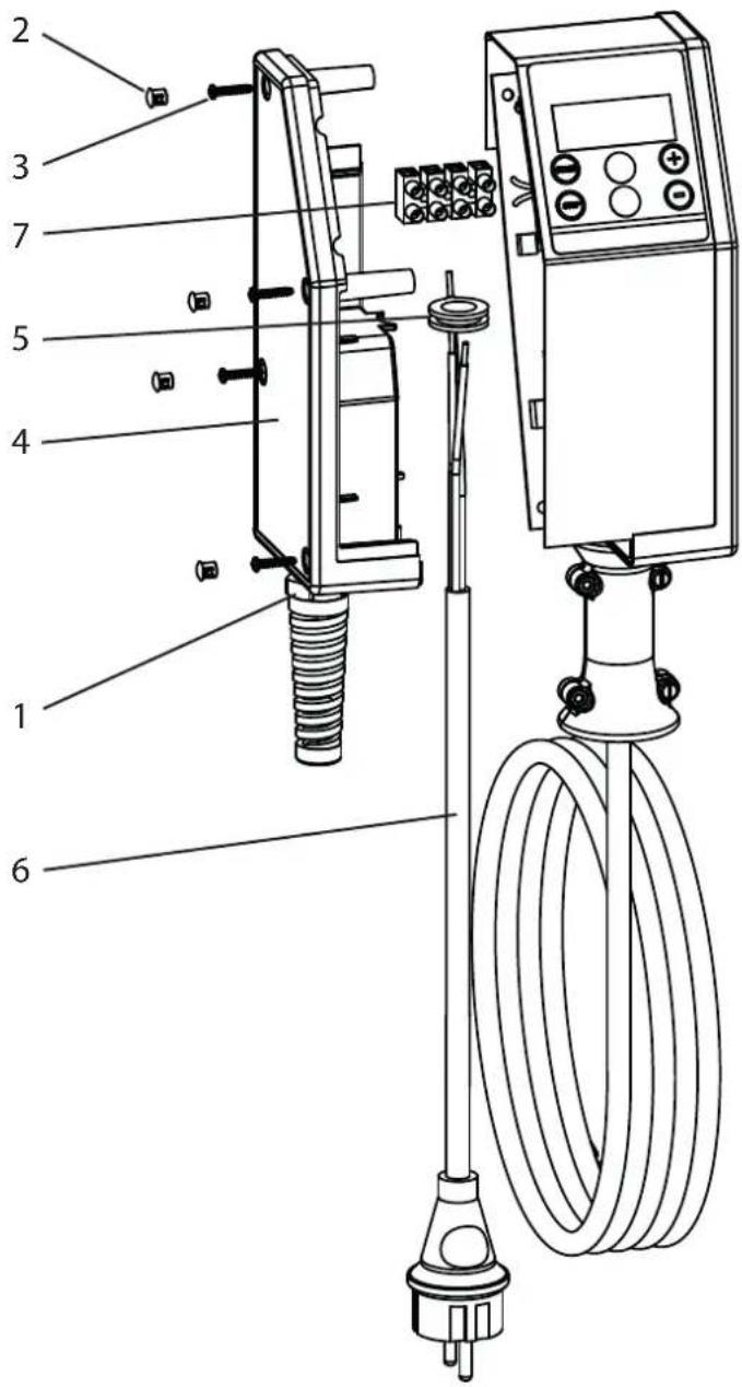
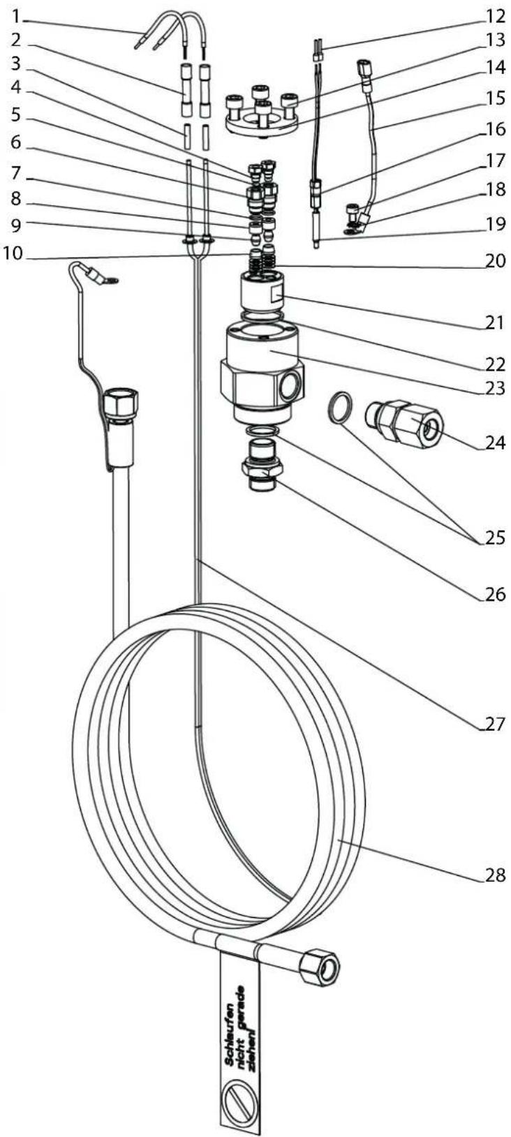
10.4 SPARE PARTS LIST HEATING HOSE TEMPSPRAY-H326 / -H226
| POS. | RTDER-NO DESIGNATION | |
| 1 2312 | 111 Wire brown (2) | |
| 2 2313 | 390 Ferrule (2) | |
| 3 990 | 0 325 Socket head cap screw M6x16 DIN 912 (4) | |
| 4 2311 | 137 Pressure plate | |
| 5 998 | 4 506 9984 515 | HP Hose DN10-15m (H226) HP Hose DN10-30m (H326) |
| 6 3054 | 990 Wire end ferrule (2) | |
| 7 2312 | 199 Flexible insulating tubing (2) | |
| 8 2312 | 110 Wire green/yellow | |
| 9 2311 | 136 Sensor screw connection | |
| 10 99 | 00 392 Socket head cap screw M4x6 DIN 912 (4) | |
| 11 99 | 22 101 External tooth lock washer A4,3 DIN6797 | |
| 12 230 | 8 061 NTC Temperature sensor | |
| 14 23 | 12 2852312 115 | Heating wire (H226)Heating wire (H326) |
| 15 2308 | 887 Double-ended union | |
| 16 9970 | 103 Sealing ring (2) | |
| 17 0341 | 464 Hose connector | |
| 18 2311 | 135 Material conveying housing | |
| 19 0341 | 331 Sealing ring | |
| 20 2311 | 134 Wire feed through | |
| 21 9923 | 513 Disc spring (12) | |
| 22 0335 | 320 Thrust peace (2) | |
| 23 2309 | 790 Collar seal (2) | |
| 24 0149 | 397 Packing (2) | |
| 25 9971 | 003 O-ring (2) | |
| 26 0344 | 431 Screwing (2) | |
| 27 9971 | 189 O-ring (2) | |
| 28 0344 | 432 Screwing (2) |
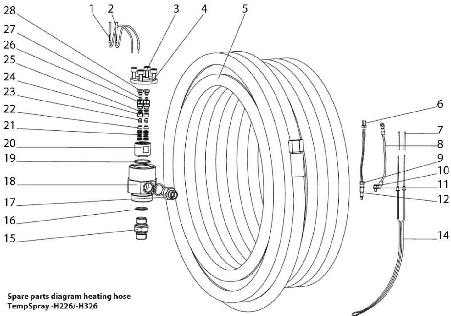
Spare parts diagram heating hose TempSpray -H226/-H326
10.5 SPARE PARTS LIST TEMPSPRAY-H126
| POS. | ORTDER-NO DESIGNATION |
| 1 9990 | 864 Cap (4) |
| 2 9905 | 115 Oval head screw D 3,17x16 (4) |
| 3 2311 | 028 Housing part left |
| 4 9950 | 244 Terminal strip (4-way) (2) |
| 5 9955 | 041 Cable bushing |
| 6 9902 | 228 Oval head self tapper 4,2x9,5 DIN7981 |
| 7 2311 | 699 Spacer sleeve (4) |
| 8 2307 | 584 Control panel heat controller |
| 9 9920 | 123 Washer A3,2 DIN125 (PA)(4) |
| 10 9910 | 103 Hexagon nut M3 DIN934 (4) |
| 11 9950 | 372 Earthing label |
| 12 2311 | 083 Display |
| 13 2311 | 138 Control panel |
| POS. | ORTDER-NO DESIGNATION |
| 14 997 | 1 484 Round section cord (2) |
| 15 231 | 1 027 Housing part right |
| 16 231 | 1 171 Overheating control |
| 17 231 | 2 322 Wagner logo |
| 18 230 | 7 585 Heat controller for 230V control unit |
| 19 231 | 1 655 Heating hose assy. |
| 20 034 | 4 408 Anti-kink (2) |
| 21 990 | 0 711 Socket head cap screw M 4x12 DIN 84 A (4) |
| 22 991 | 0 108 Hexagon nut M4 DIN934 (4) |
| 23 025 | 2 485 Power cord |
| 24 034 | 4 425 Power cable adhesive label |
| 25 995 | 2 685 Cable coupling with antikink spiral |
| 26 995 | 2 686 Hexagon nut |
10.6 SPARE PARTS LIST HEATING HOSE TEMPSPRAY-H126
| POS. | ORTDER-NO DESIGNATION |
| 1 2313 | 432 Wire brown (2) |
| 2 2313 | 390 Ferrule (2) |
| 3 2312 | 113 Flexible insulating tubing (2) |
| 4 0344 | 432 Screwing small (2) |
| 5 9971 | 189 O-ring (2) |
| 6 0344 | 431 Screwing (2) |
| 7 9971 | 003 O-ring (2) |
| 8 0149 | 397 Packing (2) |
| 9 2309 | 790 Collar seal (2) |
| 10 0335 | 320 Thrust piece (2) |
| 12 3054 | 990 Wire end ferrule (2) |
| 13 9900 | 325 Socket head cap screw M6x16 DIN 912 (4) |
| 14 2311 | 137 Pressure plate |
| 15 2312 | 097 Wire green/yellow |
| 16 2311 | 136 Sensor screw connection |
| 17 9900 | 392 Socket head cap screw M4x6 DIN 912 |
| 18 9922 | 101 External tooth lock washer A4,3 DIN6797 |
| 19 2308 | 061 NTC Temperature sensor |
| 20 9923 | 513 Disc spring (12) |
| 21 2311 | 134 Wire feed through |
| 22 0341 | 331 Sealing ring |
| 23 2311 | 135 Material conveying housing |
| 24 0344 | 273 Swivel assy. (1/4" NPSM) |
| 25 9970 | 103 Sealing ring (2) |
| 26 0104 | 475 Double nipple |
| 27 2312 | 116 Heating wire |
| 28 0344 | 290 HP Hose |
For safety reasons, we would recommend having the device checked by an expert as required but at least every 6 months to ensure that it can continue to operate safely.
In the case of unused devices, the check can be postponed until they are next started up.
All (potentially deviating) national inspection and maintenance regulations must also be observed.
If you have any questions, please contact the customer service team at Wagner.
IMPORTANT INFORMATION ON PRODUCT LIABILITY
According to an EU directive, the manufacturer is only liable without limitation for faults in the product if all parts come from the manufacturer or have been approved by the manufacturer and have been mounted to the device and are operated properly. If third-party accessories or spare parts are used, the manufacturer is exonerated wholly or partly from his/her liability if use of the third-party accessories or spare parts have caused a defect in the product. In extreme cases, the relevant authorities can completely prohibit using the entire device.
With original WAGNER accessories and spare parts, compliance with all safety regulations is guaranteed.
NOTE ON DISPOSAL
In observance of the European Directive 2002/96/EC on waste electrical and electronic equipment and implementation in accordance with national law, this product is not to be disposed of together with household waste material but must be recycled in an environmentally friendly way!

Wagner or one of our dealers will take back your used Wagner waste electrical or electronic equipment and will dispose of it for you in an environmentally friendly way. Please ask your local Wagner service centre or dealer for details or contact us direct.
GUARANTEE DECLARATION
(Status 01.02.2009)
1. Scope of guarantee
All Wagner professional colour application devices (hereafter referred to as products) are carefully inspected, tested and are subject to strict checks under Wagner quality assurance. Wagner exclusively issues extended guarantees to commercial or professional users (hereafter referred to as “customer”) who have purchased the product in an authorised specialist shop, and which relate to the products listed for that customer on the Internet under www.wagner-group.com/profi-guarantee.
The buyer's claim for liability for defects from the purchase agreement with the seller as well as statutory rights are not impaired by this guarantee.
We provide a guarantee in that we decide whether to replace or repair the product or individual parts, or take the device back and reimburse the purchase price. The costs for materials and working hours are our responsibility. Replaced products or parts become our property.
2. Guarantee period and registration
The guarantee period amounts to 36 months. For industrial use or equal wear, such as shift operations in particular, or in the event of rentals it amounts to 12 months.
Systems driven by petrol or air are also guaranteed for a 12 month period.
The guarantee period begins with the day of delivery by the authorised specialist shop. The date on the original purchase document is authoritative.
For all products bought in authorised specialist shops from 01.02.2009 the guarantee period is extended to 24 months providing the buyer of these devices registers in accordance with the following conditions within 4 weeks of the day of delivery by the authorised specialist shop.
Registration can be completed on the Internet under www.wagner-group.com/profi-guarantee.
The guarantee certificate is valid as confirmation, as is the original purchase document that carries the date of the purchase. Registration is only possible if the buyer is in agreement with having the data being stored that is entered during registration.
When services are carried out under guarantee the guarantee period for the product is neither extended nor renewed.
Once the guarantee period has expired, claims made against the guarantee or from the guarantee can no longer be enforced.
3. Handling
If defects can be seen in the materials, processing or performance of the device during the guarantee period, guarantee
claims must be made immediately, or at the latest within a period of 2 weeks.
The authorised specialist shop that delivered the device is entitled to accept guarantee claims. Guarantee claims may also be made to the service centres named in our operating instructions. The product has to be sent without charge or presented together with the original purchase document that includes details of the purchase date and the name of the product. In order to claim for an extension to the guarantee, the guarantee certificate must be included.
The costs as well as the risk of loss or damage to the product in transit or by the centre that accepts the guarantee claims or who delivers the repaired product, are the responsibility of the customer.
4. Exclusion of guarantee
Guarantee claims cannot be considered
-for parts that are subject to wear and tear due to use or other natural wear and tear, as well as defects in the product that are a result of natural wear and tear, or wear and tear due to use. This includes in particular cables, valves, packaging, jets, cylinders, pistons, means-carrying housing components, filters, pipes, seals, rotors, stators, etc. Damage due to wear and tear that is caused in particular by sanded coating materials, such as dispersions, plaster, putty, adhesives, glazes, quartz foundation.
-in the event of errors in devices that are due to non-compliance with the operating instructions, unsuitable or unprofessional use, incorrect assembly and/or commissioning by the buyer or by a third party, or utilisation other than is intended, abnormal ambient conditions, unsuitable coating materials, unsuitable operating conditions, operation with the incorrect mains voltage supply/frequency, over-operation or defective servicing or care and/or cleaning.
-for errors in the device that have been caused by using accessory parts, additional components or spare parts that are not original Wagner parts.
-for products to which modifications or additions have been carried out.
-for products where the serial number has been removed or is illegible
-for products to which attempts at repairs have been carried out by unauthorised persons.
-for products with slight deviations from the target properties, which are negligible with regard to the value and usability of the device.
-for products that have been partially or fully taken apart.
5. Additional regulations.
The above guarantees apply exclusively to products that have been bought by authorised specialist shops in the EU, CIS, Australia and are used within the reference country.
If the check shows that the case is not a guarantee case, repairs are carried out at the expense of the buyer.
The above regulations manage the legal relationship to us concludingly. Additional claims, in particular for damages and losses of any type, which occur as a result of the product or its use, are excluded from the product liability act except with regard to the area of application.
Claims for liability for defects to the specialist trader remain unaffected.
German law applies to this guarantee. The contractual language is German. In the event that the meaning of the German and a foreign text of this guarantee deviate from one another, the meaning of the German text has priority.
J. Wagner GmbH
Division Professional Finishing
Otto Lilienthal Strasse 18
88677 Markdorf
Federal Republic of Germany
Subject to modifications · Printed in Germany
EU Declaration of conformity
We declare under sole responsibility that this product conforms to the following relevant stipulations:
2014/35/EU, 2014/30/EU, 2011/65/EU, 2012/19/EU
Applied harmonised norms:
EN 60519-1, EN 60519-2, EN 60204-1, EN 61000-3-2,
EN 61000-3-3, EN 61000-6-1, EN 61000-6-3
The EU declaration of conformity is enclosed with the product.
If required, it can be re-ordered using order number 2313841.
TempSpray - H326 / -H226
3.3 TRANSPORT
TempSpray-H326 et TempSpray-H226:
natural_image
Technical line drawing of a mechanical power pump with hoses and wheels (no text or symbols)TempSpray-H126:
4.2 TEMPSPRAY-H126
4.3 MISE SOUS TENSION
9.2 TEMPSPRAY-H126
REEMPLACER LE CORDON D'ALIMENTATION

Danger
Arrêter l'appareil.
9.4 AIDE EN CAS DE PANNES
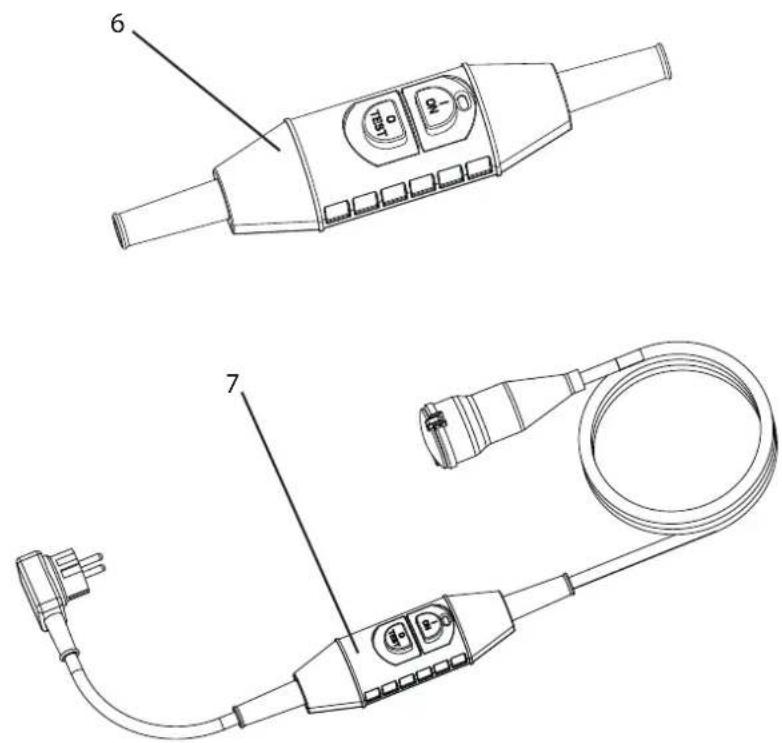
Illustration des accessoires
10.3 LISTE DE PIÈCES DE RECHANGE TEMPSPRAY-H326 / -H226
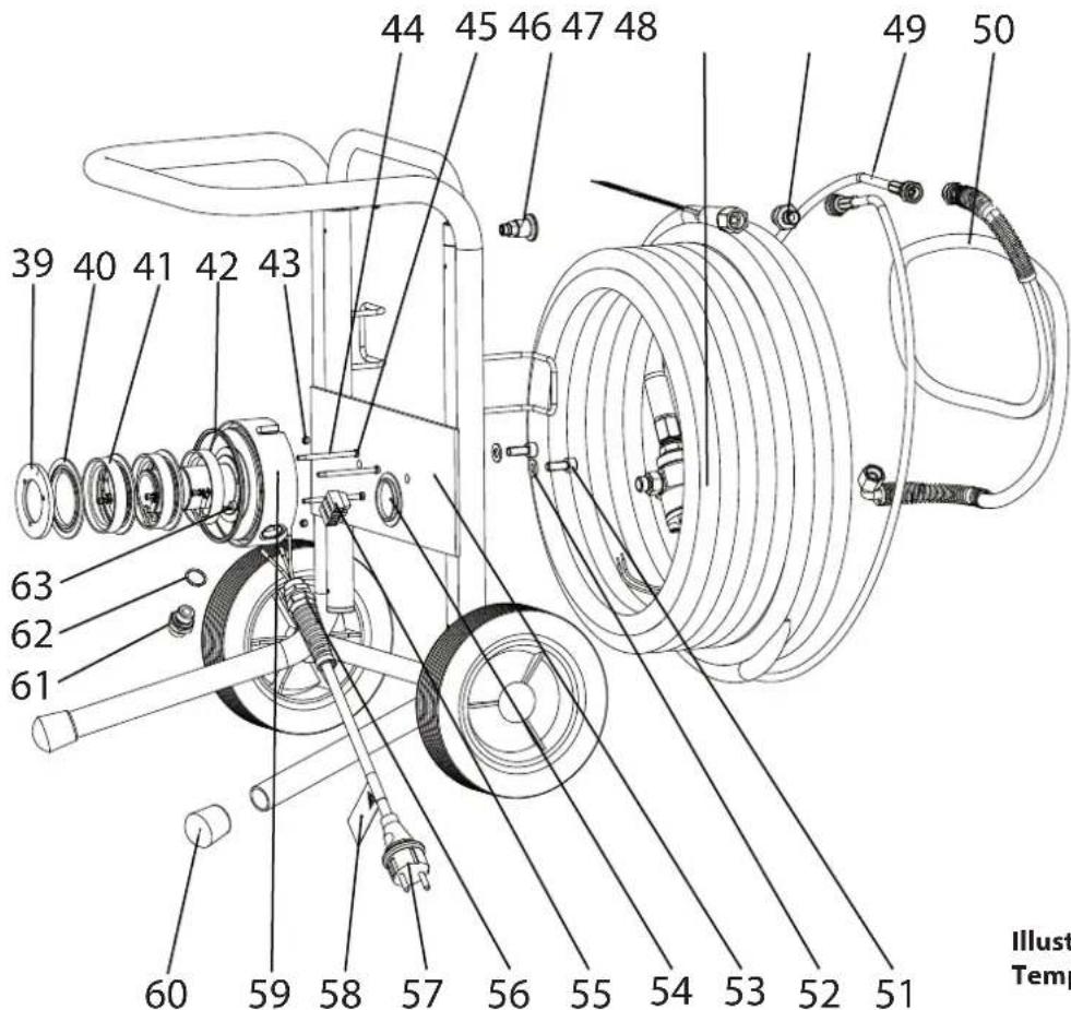
Illustration des pièces de rechange TempSpray -H226/-H326
10.4 LISTE DE PIÈCES DE RECHANGE TUYAU DE PEINTURE CHAUFFANT TEMPSPRAY-H326 / -H226
INDICATION DE MISE AU REBUT
Division Professional Finishing
Otto Lilienthal Strasse 18
88677 Markdorf
3 APPARAATBESCHRIJVING 85
3.1 Algemene werking van de apparaten ____ 85
3.2 Overzichten 86
3.3 Transport 87
3.4 Technische gegevens TempSpray-H326 88
3.5 Technische gegevens TempSpray-H226 88
3.6 Technische gegevens TempSpray-H126 89
4 INBEDRIJFSTELLING 90
3 APPARAATBESCHRIJVING
3.1 ALGEMENE WERKING VAN DE APPARATEN
TempSpray - H326 / -H226
3.3 TRANSPORT
TempSpray-H326 en TempSpray-H226:
natural_image
Technical line drawing of a mechanical pump cart with hoses and wheels, no text or symbols presentTempSpray-H126:
Appendage: 3/8" NPSM
Slangverlengstuk: DN5, 1 m,
met staalwapening
Binnendiameter: 5 mm
Lengte: 1 m
Appendage: 1/4" NPSM
Aansluitslangstuk:
DN6, 1,6 m,
met textielwapening
Binnendiameter: 6 mm
Lengte: 1,6 m
Appendage: 1/4" NPSM
Appendage: 3/8" NPSM
Slangverlengstuk: DN5, 1 m,
met staalwapening
Binnendiameter: 5 mm
Lengte: 1 m
Appendage: 1/4" NPSM
Aansluitslangstuk:
DN6, 1,6 m,
met textielwapening
Binnendiameter: 6 mm
Lengte: 1,6 m
Appendage: 1/4" NPSM
Appendage: 1/4" NPSM
4.2 TEMPSPRAY-H126
4.3 INSCHAKELEN
9 REPARATIES AAN HET APPARAAT

Gevaar
9.2 TEMPSPRAY-H126 NETSNOER VERVANGEN

9.4 HULP BIJ STORINGEN
10.3 RESERVEONDERDELENLIJST TEMPSPRAY-H326/-H226
| POS. | BESTELNR. | BEN | AMING |
| 2311 | 664 | Frontdeksel compl.(Pos. 1-7,33,34,36,38) | |
| 1 2311 | 069 | Display | |
| 2 2307 | 584 | Verwarmingsregelaar bedieningsdeel | |
| 3 9920 | 123 | Ring A3,2 | DIN 126 (PA)(4) |
| 4 9903 | 343 | Schroefdraadinkepende schroefM3x6 | DIN 7500 (4) |
| 5 2309 | 735 | Steektong | |
| 6 9920 | 104 | Ring A4,2 | DIN 125 (4) |
| 7 9922 | 101 | Tandschijf aan de buitenkant getand | |
| 8 2311 | 139 | Koolborstel (4) | |
| 9 9903 | 322 | Schroefdraadinkepende schroefM4x10 | DIN 7500 (14) |
| 10 9955 | 041 | Kabeldoorvoertülle (2) | |
| 11 2312 | 445 | Afdichting | |
| 12 9990 | 374 | Handgreep M10 | |
| 13 2312 | 295 | Afdekdopje (2) | |
| 14 9920 | 106 | Ring A10,5 | DIN 125 |
| 15 2312 | 297 | Rol (2) | |
| 16 9903 | 347 | Lenskopschroef M10x20 | |
| 17 2311 | 258 | Slanggeleiding | |
| 2315 | 901 | Slanggeleiding compl. (Pos. 13,15,17) | |
| 18 9900 | 106 | Zeskantschroef M6x12 | DIN933 |
| 19 9990 | 232 | Buisklem | |
| 20 2312 | 296 | Rolgeleiding | |
| 2316 | 034 | Rolgeleiding compl. (Pos. 13,15,20) | |
| 21 2311 | 168 | Trommelschaal achter | |
| 22 9910 | 204 | Zeskantmoer M6 | DIN985(5) |
| 23 2311 | 167 | Trommelschaal voor | |
| 24 9900 | 108 | Zeskantschroef M6x20 | DIN933 (4) |
| 25 9994 | 962 | Glijlager | |
| 26 2311 | 002 | Trommelbehuizing | |
| 27 9920 | 614 | Pasring (2) | |
| 28 9922 | 535 | Borgring (2) | |
| 29 2311 | 171 | Temperatuurbewaking | |
| 30 2307 | 585 | Verwarmingsregelaar stuurgedeelte230V | |
| 31 2306 | 244 | Klemlijst (6-voudig) | |
| 32 2311 | 150 | Draaigeleiding compl. | |
| 33 9921 | 902 | Borgplaatje D6 | DIN 6799 |
| POS. | BESTELNR. | BENAMING |
| 34 231 | 1 153 | Schroefdraadstang |
| 35 231 | 1 148 | Buis compl. |
| 36 990 | 1 319 | Schroefdraadinzetstuk |
| 37 990 | 06 003 | Schroefdraadinkepende schroefM6x25 DIN 7500 (4) |
| 38 231 | 2 233 | Stergreep |
| 39 231 | 1 144 | Eindring |
| 40 231 | 1 143 | Isoleerring (3) |
| 41 231 | 1 142 | Slijpring (3) |
| 42 230 | 9 732 | Viltafdichtstrook |
| 43 990 | 1 114 | Borgpen M5x6 DIN 916 (2) |
| 44 230 | 9 733 | Krimpslangstuk (3) |
| 45 990 | 0 743 | Cilinderschroef M4x60 DIN 84 A (3) |
| 46 025 | 2 455 | Miniraster |
| 47 231 | 11 656 | Verwarmingsslang compl. (H226) |
| 2311 657 | Verwarmingsslang compl. (H326) | |
| 48 036 | 7 561 | Dubbel aansluitstuk |
| 49 998 | 4 458 | Slangverlengstuk |
| 50 998 | 4 590 | Slangverlengstuk compl. |
| 51 990 | 0 318 | Cilinderschroef M8x20 DIN 912 (2) |
| 52 992 | 0 102 | Ring (2) |
| 53 231 | 1 248 | Slangwagen compl. |
| 54 231 | 2 294 | Afdekdopje |
| 55 995 | 0 212 | Klemlijst (3-voudig) |
| 56 995 | 2 685 | Kabelwartel met knikbescherming |
| 57 026 | 1 352 | Netsnoer compl. |
| 58 034 | 4 425 | Sticker netsnoer |
| 59 231 | 1 145 | Opslag |
| 2315 770 | Opslag compl. (Pos.39-45,54-59,61-63) | |
| 60 999 | 0 866 | Rubberen dop (2) |
| 61 034 | 1 350 | Dubbel aansluitstuk |
| 62 997 | 0 103 | Afdichtring |
| 63 230 | 9 734 | Krimpslangstuk |

www.wagner-group.com/profi-guarantee.
Division Professional Finishing
Otto Lilienthal Strasse 18
88677 Markdorf


- TEMPSPRAY H126, H226, H326
- REPARATUREN AM GERÄT 15
- EXPLOSIONSSCHUTZ
- TRANSPORT
- TECHNISCHE DATEN TEMPSPRAY-H326
- EINSCHALTEN
- REPARATUREN AM GERÄT
- TEMPSPRAY-H126
- Translation of the original operating instructions
- WARNING!
- Ensure safety!
- Table of Contents
- SAFETY REGULATIONS FOR AIRLESS SPRAYING 31
- OVERVIEW OF APPLICATION 33
- DESCRIPTION OF UNIT 33
- STARTUP 38
- REPAIRS AT THE UNIT 42
- SPARE PARTS AND ACCESSORIES 47
- SAFETY REGULATIONS FOR AIRLESS SPRAYING
- FLASH POINT
- EXPLOSION PROTECTION
- DANGER OF EXPLOSION AND FIRE FROM SOURCES OF IGNITION DURING SPRAYING WORK
- ELECTRIC CHARGE (SPARK AND FLAME FORMATION)
- EARTHING OF THE OBJECT
- PROTECTIVE EARTHING OF THE HEATING HOSE
- USE OF UNITS ON BUILDING SITES AND WORKSHOPS
- HIGH PRESSURE HOSE
- PERSONAL PROTECTION WHILE HOT SPRAYING
- CLEANING THE UNIT
- CLEANING THE UNIT WITH SOLVENTS
- WORK OR REPAIRS AT THE ELECTRICAL EQUIPMENT
- WORK AT ELECTRICAL COMPONENTS
- MAX. OPERATING PRESSURE
- SETTING
- OVERVIEW OF APPLICATION
- RANGE OF APPLICATION
- COATING MATERIAL
- COATING MATERIALS WITH SHARP-EDGED ADDITIONAL MATERIALS
- DESCRIPTION OF UNIT
- GENERAL FUNCTION OF THE DEVICES
- EXPLANATORY DIAGRAM
- TECHNICAL DATA TEMPSPRAY-H326
- TECHNICAL DATA TEMPSPRAY-H226
- TECHNICAL DATA TEMPSPRAY-H126
- STARTUP
- TEMPSPRAY-H326 AND TEMPSPRAY-H226
- CONNECTION TO THE MAINS NETWORK
- CLEANING PRESERVING AGENT WHEN STARTING-UP OF OPERATION INITIALLY
- TEMPSPRAY-H126
- CONNECTION TO THE MAINS NETWORK
- CLEANING PRESERVING AGENT WHEN STARTING-UP OF OPERATION INITIALLY
- SWITCH-ON
- TEMPERATURE ADJUSTMENT
- HANDLING THE HIGH-PRESSURE HOSE
- INTERRUPTION OF WORK
- CLEANING THE DEVICE
- CLEANING THE UNIT FROM THE OUTSIDE
- SERVICING
- GENERAL SERVICING
- Minimum check before every startup:
- Check at periodical intervals:
- REPAIRS AT THE UNIT
- TEMPSPRAY-H326 AND TEMPSPRAY-H226 CHANGING THE POWER CORD
- CHANGING THE POWER CORD
- INSULATION TEST WITH 1000 VOLTS DC DURING DEVICE INSPECTION BY SERVICE
- CIRCUIT DIAGRAM TEMPSPRAY-H126
- SPARE PARTS AND ACCESSORIES
- IMPORTANT INFORMATION ON PRODUCT LIABILITY
- NOTE ON DISPOSAL
- GUARANTEE DECLARATION
- Scope of guarantee
- Guarantee period and registration
- Handling
- Exclusion of guarantee
- Guarantee claims cannot be considered
- Additional regulations.
- EU Declaration of conformity
- MISE SOUS TENSION
- REEMPLACER LE CORDON D'ALIMENTATION
- INDICATION DE MISE AU REBUT
- APPARAATBESCHRIJVING 85
- INBEDRIJFSTELLING 90
- APPARAATBESCHRIJVING
- ALGEMENE WERKING VAN DE APPARATEN
- INSCHAKELEN
- REPARATIES AAN HET APPARAAT
- TEMPSPRAY-H126 NETSNOER VERVANGEN
Brand : WAGNER
Model : TempSpray H326
Category : Paint spray