35.1109 - Environment thermometer TFA - Free user manual and instructions
Find the device manual for free 35.1109 TFA in PDF.
| Product type | Radio-controlled weather station with outdoor sensor |
| Brand | TFA |
| Model | 35.1109 |
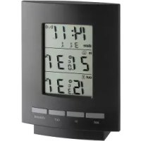
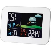
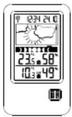
| Display | LCD with 5 sections: time/calendar, weather forecast, moon phases, indoor data, outdoor data |
| Radio-controlled time | DCF-77 (77.5 kHz), range ~1500 km, automatic reception 2x/day |
| Time zone | Adjustable from -12 to +12 hours |
| Calendar | Year (2011-2039), month, date, with 8 moon phases |
| Weather forecast | Icons (sunny, cloudy, rainy) with trend indicator |
| Indoor temperature | -9.9°C to +59.9°C (resolution 0.1°C) |
| Outdoor temperature | -39.9°C to +59.9°C (resolution 0.1°C) |
| Indoor humidity | 20% to 95% (resolution 1%) |
| Outdoor humidity | 1% to 99% (resolution 1%) |
| MIN/MAX function | Display and reset of min/max temperatures and humidity |
| Outdoor transmission | 868 MHz, range up to 100 m (free field) |
| Station power supply | 2 AAA (LR3) 1.5 V batteries |
| Transmitter power supply | 2 AAA (LR3) 1.5 V batteries |
| Transmitter dimensions | 36 x 16 x 102.6 mm |
| Mounting | Station on stand or wall; transmitter wall or flat surface |
| Maintenance | Soft damp cloth, no solvents |
| Safety instructions | Keep out of reach of children, handle batteries with care |
Frequently Asked Questions - 35.1109 TFA
User questions about 35.1109 TFA
0 question about this device. Answer the ones you know or ask your own.
Ask a new question about this device
Download the instructions for your Environment thermometer in PDF format for free! Find your manual 35.1109 - TFA and take your electronic device back in hand. On this page are published all the documents necessary for the use of your device. 35.1109 by TFA.
USER MANUAL 35.1109 TFA
WETTERVHERSAGESYMBOLE:
Thank you for choosing this wireless weather station from TFA.
BEFORE YOU USE IT
Please be sure to read the instruction manual carefully.
This information will help you to familiarise yourself with your new device, learn all of its functions and parts, find out important details about its first use and how to operate it, and get advice in the event of faults.
Following the instruction manual for use will prevent damage to the device and loss of your statutory rights arising from defects due to incorrect use.
We shall not be liable for any damage occurring as a result of not following these instructions.
Please take particular note of the safety advice!
Please look after this manual for future reference.
SCOPE OF SUPPLY:
- Weather Station (basic unit)
- Outdoor transmitter
- Instruction manual
FIELD OF OPERATION AND ALL OF THE BENEFITS OF YOUR NEW WEATHER STATION AT A GLANCE
- DCF Radio controlled time with manual setting option
- Time reception ON/OFF (user selectable)
- Time zone option ±12 hours
- Calendar display (year only in setting mode)
- Display 8 moon phases
- Weather forecasting with weather tendency indicator
- Indoor and outdoor temperature display with MIN/MAX records
- Temperature display in ^ C
- Indoor and outdoor humidity display
- Humidity data display as RH%
- Low battery indicator
- Table standing or wall mounting
FOR YOUR SAFETY:
- The product is exclusively intended for the field of application described above. The product should only be used as described within these instructions.
- Unauthorised repairs, modifications or changes to the product are prohibited.

Caution! Risk of injury:
- Keep this instrument and the batteries out of reach of children.
- Batteries must not be thrown into the fire, short-circuited, taken apart or recharged. Risk of explosion!
- Batteries contain harmful acids. Low batteries should be changed as soon as possible to prevent damage caused by a leaking battery. Never use a combination of old and new batteries together or batteries of different types. Wear chemical-resistant protective gloves and glasses when handling leaked batteries.
! Important information on product safety!
- Do not expose the instrument to extreme temperatures, vibration or shock.
- The outdoor transmitter is protected against splash water, but is not watertight. Choose a shady and dry position for the transmitter.
Thermo-Hygro Transmitter
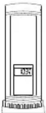
Remote transmission of outdoor temperature and humidity to weather station by 868MHz
- Alternately display the outdoor temperature and humidity readings on LCD
- Wall mounting case
- Mounting at a sheltered place. Avoid direct rain and sunshine
TO INSTALL AND REPLACE BATTERIES IN THE THERMO-HYGRO TRANSMITTER
The outdoor thermo-hygro transmitter uses 2 × AAA, IEC LR3, 1.5V batteries. To install and replace the batteries, please follow the steps below:
- Remove the battery cover by pushing the battery cover upwards with your thumb.
- Insert the batteries, observing the correct polarity (see battery compartment marking).
- Replace the battery cover on the unit.
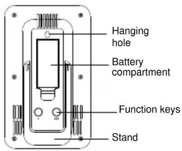
TO INSTALL AND REPLACE BATTERIES IN THE WEATHER STATION
The weather station uses 2 x AAA, IEC LR3, 1.5V batteries. To install and replace the batteries, please follow the steps below:
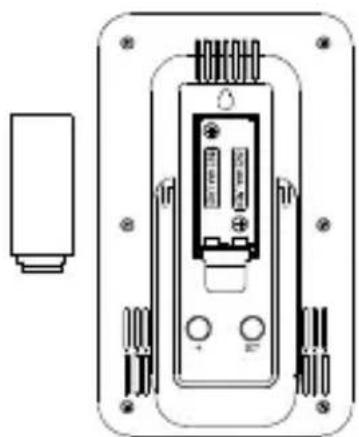
- Insert finger or other solid object in the space at the bottom center of the battery compartment and lift up to remove the cover.
- Insert batteries observing the correct polarity (see marking).
- Replace compartment cover.
Battery replacement
- Replace the batteries when the battery symbol of the weather station appears on the upper display.
- When the batteries of the transmitter are used up, the low battery icon appears next to the outdoor temperature display.
Note:
In the event of changing batteries in any of the units, all units need to be reset by following the setting up procedures. This is due to a random security code assigned by the transmitter at start-up. This code must be received and stored by the weather station in the first 3 minutes of power being supplied to the transmitter.
SETTING UP
- First, insert the batteries in the transmitter (see "To install and replace batteries in the thermo-hygro transmitter" above).
- Within 2 minutes of powering up the transmitter, insert the batteries in the weather station (see "To install and replace batteries in the weather station" above). Once the batteries are in place, all segments of the LCD will light up briefly. Following the indoor temperature/humidity and the time as 00:00 will be displayed. If these information are not displayed on the LCD after 60 seconds, remove the batteries and wait for at least 60 seconds before reinserting them. Once the indoor data is displayed user may proceed to the next step.
- After the batteries are inserted, the weather station will start receiving data signal from the transmitter. The outdoor temperature and humidity data should then be displayed on the weather station. If this does not happen after 2 minutes, the batteries will need to be removed from both units and reset from step 1.
- In order to ensure sufficient 868 MHz transmission however, the distance between the weather station and the transmitter should not be more than 100 meters (see notes on "Positioning" and "868 MHz Reception").
Note:
In the event of changing batteries of the units, ensure the batteries do not spring free from the contacts. Always wait at least 1 minute after removing the batteries before reinserting, otherwise start up and transmission problems may occur.
- Once the outdoor data reception test period is completed, the DCF tower icon in the clock display will start flashing in the upper left corner. This indicates that the clock has detected that there is a radio signal present and is trying to receive it. When the time code is received, the DCF tower becomes permanently lit and the time will be displayed.
DCF RADIO CONTROLLED TIME
The time base for the radio controlled time is a Cesium Atomic Clock operated by the Physikalisch Technische Bundesanstalt Braunschweig which has a time deviation of less than one second in one million years. The time is coded and transmitted from Mainflingen near Frankfurt via frequency signal DCF-77 (77.5 kHz) and has a transmitting range of approximately 1,500 km. Your radio-controlled weather station receives this signal and converts it to show the precise time in summer or wintertime.
The quality of the reception depends greatly on the geographic location. In normal cases, there should be no reception problems within a 1,500km radius of Frankfurt.
DCF reception is done twice daily at 02:00 and 03:00 am. If the reception is not successful at 03:00 am, then the next reception takes place the next hour and so on until 06:00am, or until the reception is successful. If the reception is not successful at 06:00 am, then the next attempt will take place the next day at 02:00 am.
If the tower icon flashes, but does not set the time or the DCF tower does not appear at all, then please take note of the following:
- Recommended distance to any interfering sources like computer monitors or TV sets is a minimum of 1.5 - 2 meters.
- Within ferro-concrete rooms (basements, superstructures), the received signal is naturally weakened. In extreme cases, please place the unit close to a window and/ or point its front or back towards the Frankfurt transmitter.
- During nighttime, the atmospheric disturbances are usually less severe and reception is possible in most cases. A single daily reception is adequate to keep the accuracy deviation below 1 second.
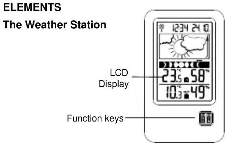
FUNCTION KEYS:
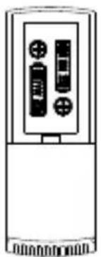
Weather Station:
The weather station has 3 easy to use function keys: 1 key on the front, and 2 keys on the back
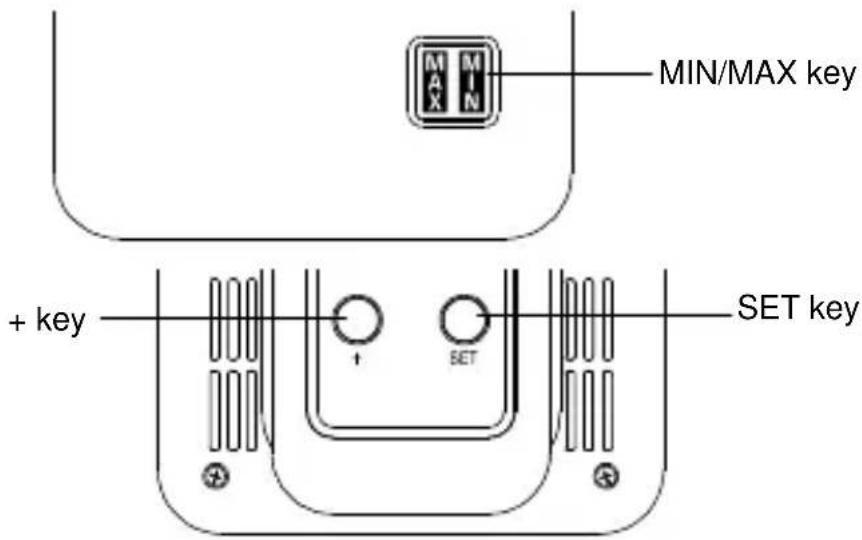
SET key
- Press and hold the key to enter manual setting modes: time zone, manual time setting, calendar, time reception ON/OFF
+key - Increase, change, toggle all values in manual set mode
MIN/MAX key
- Press shortly to toggle between indoor and outdoor MAX/MIN temperature and current temperature
LCD SCREEN
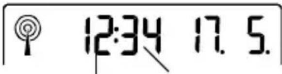
The LCD screen is split into 5 sections displaying the information for time/calendar, weather forecast, moon phase, indoor data, and outdoor data.
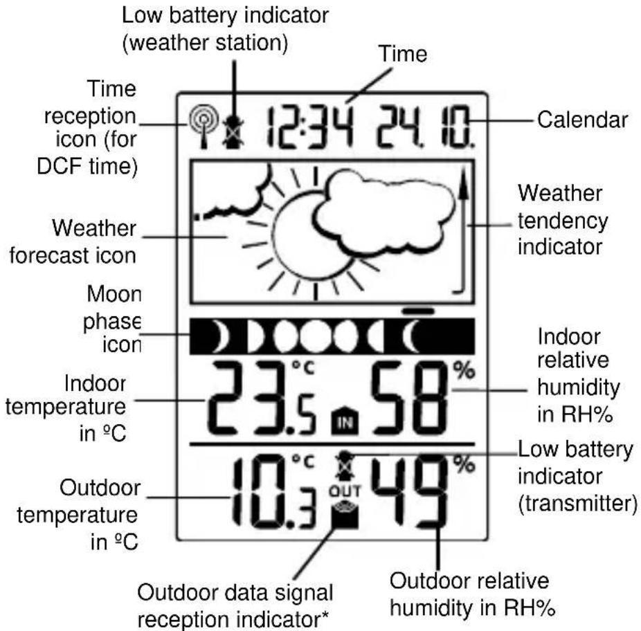
- When the signal is successfully received by the weather station, the outdoor transmission icon will be switched on. (If not successful, the icon will not be shown on LCD). The user can then easily see whether the last reception was successful (icon on) or not (icon off).
MANUAL SETTINGS:
The following manual settings can be changed by pressing and holding the SET key:
Time zone setting
- Manual time setting
Calendar setting
Time reception ON/OFF setting
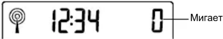
TIME ZONE SETTING:
12:34

Flashing
The time zone default of the weather station is "0". To set a different time zone:
- The current time zone value starts flashing.
- Use the ^+ key to set the time zone. The range runs from 0 to -12 and then runs from +12 back to 0 in consecutive 1-hour intervals.
- Confirm with the SET key and enter the Manual Time Setting.
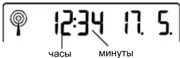
MANUAL TIME SETTING:
In case the weather station cannot detect the DCF-signal (for example due to disturbances, transmitting distance, etc.), the time can be manually set. The clock will then work as a normal quartz clock.
Hour flashing
Minutes flashing
- The hour digit will start flashing.
- Use the ^+ key to set the hour.
- Press again the SET key to set the minutes. The minute digits start flashing.
- Use the ^+ key to set the minutes.
- Confirm with the SET key and enter the Calendar setting.
Note:
The unit will still try and receive the signal despite it being manually set. When it does receive the signal, it will change the manually set time into the received time.
During reception attempts the DCF tower icon will flash. If reception has been unsuccessful, then the DCF tower icon will not appear but reception will still be attempted the following day.
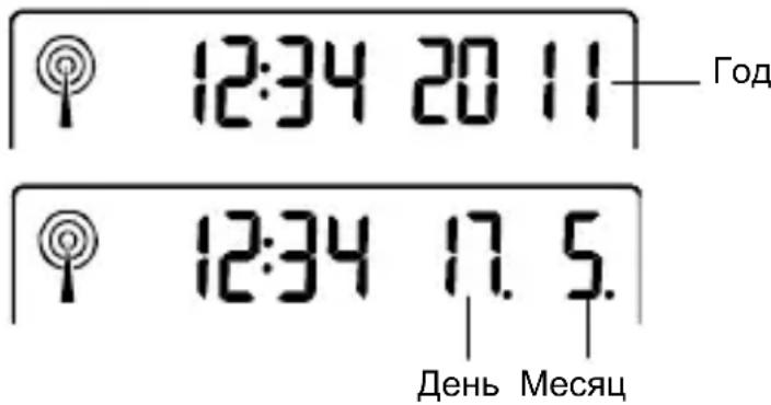
CALENDAR SETTING:
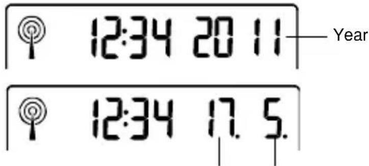
Date and month
The date default of the weather station is 1.1.2011.Once the radio-controlled time signals are received, the date is automatically updated. However, if the signals are not received, the date can also be set manually.
- The year starts flashing.
- Use the + key to set the year (between year 2011-2039).
- Press the SET key again to confirm and to enter the month setting. The month starts flashing.
- Use the + key to set the month.
- Press the SET key again to confirm and to enter the date setting mode. The date starts flashing.
- Use the ^+ key to set the date.
- Confirm all calendar settings with the SET key and enter the Time reception ON/OFF setting.
TIME RECEPTION ON/OFF SETTING:
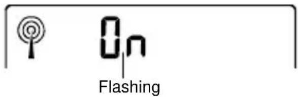
In areas where reception of the DCF time is not possible, the DCF time reception function can be turned OFF. The clock will then work as a normal Quartz clock. (Default setting is ON).
- The digit "ON" will start flashing on the LCD.
- Use the ^+ key to turn OFF the time reception function.
- Confirm with the SET key and exit the manual setting.
Note:
If the time reception function is turned OFF manually, the clock will not attempt any reception of the DCF time as long as the time reception OFF function is activated.
The time reception icon “ ” will not be displayed on the LCD.
TO EXIT THE MANUAL SETTING MODE
To exit the manual setting mode anytime during the manual setting, wait for automatic timeout. The mode will return to normal time display.
MOON PHASES SYMBOL
The moon icon of the weather station will also display all 8 moon phases throughout the year according to the set calendar. A bar segment above the moon phase will indicate the current moon phase.
Bar segment (moon phase indicator)

Waxing First Waxing Full Waning Last Waning New Crescent Quarter Gibbous Moon Gibbous Quarter Crescent Moon
WEATHER FORECAST AND WEATHER TENDENCY:
WEATHER FORECASTING ICONS:
The weather icons in the second section of LCD can be displayed in any of the following combinations:
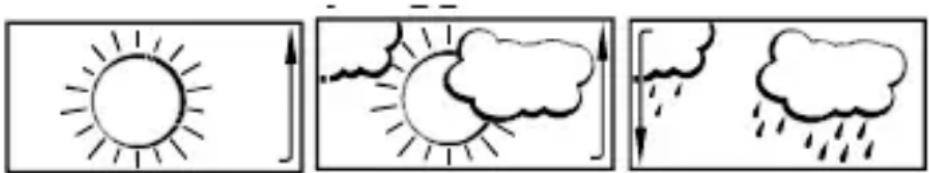
Sunny Cloudy with sunny intervals Rainy
For every sudden or significant change in the air pressure, the weather icons will update accordingly to represent the change in weather. If the icons do not change, then it means either the air pressure has not changed or the change has been too slow for the weather station to register. However, if the icon displayed is a sun or raining cloud, there will be no change of icon if the weather gets
any better (with sunny icon) or worse (with rainy icon) since the icons are already at their extremes.
The icons displayed forecasts the weather in terms of getting better or worse and not necessarily sunny or rainy as each icon indicates. For example, if the current weather is cloudy and the rainy icon is displayed, it does not mean that the product is faulty because it is not raining. It simply means that the air pressure has dropped and the weather is expected to get worse but not necessarily rainy.
Note:
After setting up, readings for weather forecasts should be disregarded for the next 12-24 hours. This will allow sufficient time for the weather station to collect air pressure data at a constant altitude and therefore result in a more accurate forecast.
Common to weather forecasting, absolute accuracy cannot be guaranteed. The weather forecasting feature is estimated to have an accuracy level of about 75% due to the varying areas the weather station has been designed for use. In areas that experience sudden changes in weather (for example from sunny to rain), the weather station will be more accurate compared to use in areas where the weather is stagnant most of the time (for example mostly sunny).
If the weather station is moved to another location significantly higher or lower than its initial standing point (for example from the ground floor to the upper floors of a house), discard the weather forecast for the next 12-24 hours. By doing this, the weather station will not mistake the new location as being a possible change in air-pressure when really it is due to the slight change of altitude.
WEATHER TENDENCY INDICATOR
The weather tendency indicators (located on the left and right sides of the weather icons) are working together with the weather icons. When the indicator points upwards, it means that the air-pressure is increasing and the weather is expected to improve, but when indicator points downwards, the air-pressure is dropping and the weather is expected to become worse.
Taking this into account, one can see how the weather has changed and is expected to change. For example, if the
indicator is pointing downwards together with cloud and sun icons, then the last noticeable change in the weather was when it was sunny (the sun icon only). Therefore, the next change in the weather will be cloud with rain icons since the indicator is pointing downwards.
Note:
Once the weather tendency indicator has registered a change in air pressure, it will remain permanently visualized on the LCD.
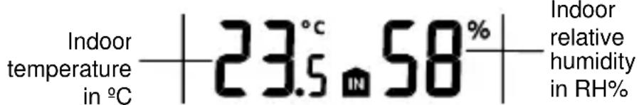
INDOOR TEMPERATURE/HUMIDITY DATA
The indoor temperature and humidity data are automatically updated and displayed on the fourth section of the LCD.
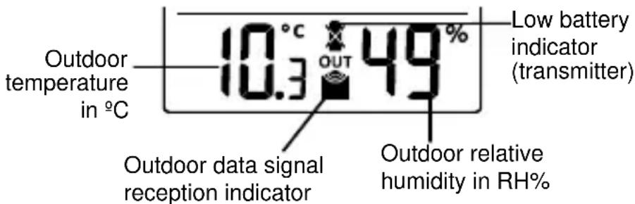
OUTDOOR TEMPERATURE/HUMIDITY DATA
The last LCD section shows the outdoor temperature and humidity, and the reception indicator.
TOGGLING AND RESETTING THE MIN/MAX DATA
TO VIEW THE MIN/MAX DATA
Press the MIN/MAX key several times to view the MIN/MAX indoor temperature and MIN/MAX outdoor temperature sequentially.
TO RESET THE MIN/MAX DATA
Press and hold MIN/MAX key for 3 seconds to reset all the indoor and outdoor temperature to current temperatures.
ABOUT THE THERMO-HYGRO TRANSMITTER
The range of the thermo-hygro transmitter may be affected by the temperature. At cold temperatures the transmitting
distance may be decreased. Please bear this in mind when positioning the transmitters. Also the batteries may be reduced in power for the thermo-hygro transmitter.
CHECKING FOR 868MHz RECEPTION
If the outdoor temperature and humidity data are not being received within three minutes after setting up (or outdoor display always show "---" in the outdoor section of the weather station during normal operation), please check the following points:
- The distance of the weather station or transmitters should be at least 2 meters away from any interfering sources such as computer monitors or TV sets.
- Avoid placing the transmitters onto or in the immediate proximity of metal window frames.
- Using other electrical products such as headphones or speakers operating on the 868MHz-signal frequency may prevent correct signal transmission or reception. Neighbors using electrical devices operating on the 868MHz-signal frequency can also cause interference.
Note:
When the 868MHz signal is received correctly, do not reopen the battery cover of either the transmitter or weather station, as the batteries may spring free from the contacts and force a false reset. Should this happen accidentally then reset all units (see "Setting up" above) otherwise transmission problems may occur.
The transmission range is around 100 meters from the thermo-hygro transmitter to the weather station (in open space). However, this depends on the surrounding environment and interference levels. If no reception is possible despite the observation of these factors, all system units have to be reset (see "Setting up" above).
POSITIONING THE WEATHER STATION
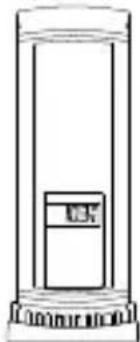
The weather station provides the option of table standing or wall mounting the unit. Before wall mounting, please check that the outdoor data can be received from the desired locations.
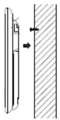
To wall mount:
- Fix a screw (not supplied) into the desired wall, leaving the head extended out by about 5mm.
- Place the weather station onto the screw, using the hanging hole on the backside. Gently pull the weather station down to lock the screw into place.
Foldout table stand:
The foldout table stand leg is located on the backside. Pull the stand out from the bottom center edge of the weather station, below the battery compartment. Once the foldout table stand is extended, place the weather station in an appropriate location.
POSITIONING THE THERMO-HYGRO TRANSMITTER
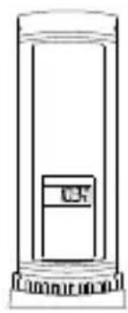
Mounting at a sheltered place. Avoid direct rain and sunshine.
The thermo-hygro transmitter can be placed onto any flat surface or wall mount using the bracket which doubles as a stand or wall mount base.
To wall mount:
- Secure the bracket onto a desired wall using the screws and plastic anchors.
- Clip the transmitter onto the bracket.
Note:
Before permanently fixing the thermo-hygro to the wall base, pace all units in the desired locations to check that the outdoor temperature
and humidity readings are receivable. In event that the signal is not received, relocate the thermo-hygro transmitter or the weather station slightly as this may help the signal reception.
CARE AND MAINTENANCE
- Clean the instrument and the transmitter with a soft damp cloth. Do not use solvents or scouring agents. Protect from moisture.
- Remove the batteries if you do not use the product for a lengthy period.
MALFUNCTION
| Problems | Troubleshooting |
| No indication on the weather station | ·Ensure batteries polarity are correct ·Change batteries |
| No transmitter reception Display "...” | ·Check batteries of external transmitter (do not use rechargeable batteries)! ·Restart the transmitter and weather station as per the manual ·Choose another place for the transmitter and/or the weather station ·Reduce the distance between the transmitter and the weather station ·Check if there is any source of interference |
| No DCF reception | ·Time reception setting “ON” ·Choose another place for the weather station ·Manual time setting ·Wait for attempted reception during the night |
| Incorrect display | ·Change batteries |
WASTE DISPOSAL
This product has been manufactured using high-grade materials and components which can be recycled and reused.
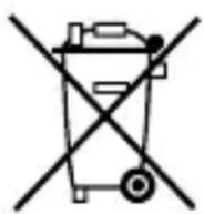
Never throw flat batteries and rechargeable batteries in household waste. As a consumer, you are legally required to take them to your retail store or to appropriate collection sites according to
national or local regulations in order to protect the environment.
The symbols for the heavy metals contained are:
Cd=cadmium, Hg=mercury, Pb=lead
This instrument is labelled in accordance with the EU Waste Electrical and Electronic Equipment Directive (WEEE).
Please do not dispose of this product with other household waste. The user is obligated to take end-of-life devices to a designated collection point for the disposal
of electrical and electronic equipment, in order to ensure environmentally-compatible disposal.
SPECIFICATIONS:
Temperature measuring range:
Indoor: -9.9°C to +59.9°C with 0.1°C resolution
("OF.L" displayed if outside this range)
Outdoor: -39.9^ to +59.9^ with 0.1^ resolution
("OF.L" displayed if outside this range)
Indoor humidity range : 20% to 95% with 1% resolution
(Display "--" if temperature is OL.F; display "19% if < 20% and "96%" if > 95%)
Outdoor humidity range : 1% to 99% with 1% resolution
(Display "--" if outside temperature is OF.L; display 1% if < 1% and 99% if >99% )
Data checking intervals
Indoor temperature : every 16 seconds
Indoor humidity : every 64 seconds
Outdoor temperature and humidity: every 4 seconds
Transmission range : up to 100 meters (open space)
Power consumption (alkaline batteries recommended):
Weather station : 2 x AAA, IEC LR3, 1.5V
Thermo-hygro transmitter : 2 x AAA, IEC LR3, 1.5V
Dimensions (L x W x H):
Weather station : 94.6 x 20mm x 157mm
Thermo-hygro transmitter : 36 x 16 x 102.6mm
Transmission frequency : 868 MHz
Maximum radio-frequency power: < 25mW
No part of this manual may be reproduced without written consent of TFA Dostmann. The technical data are correct
at the time of going to print and may change without prior notice.
The latest technical data and information about your product can be found by entering your product number on our homepage.
EU declaration of conformity
Hereby, TFA Dostmann declares that the radio equipment type 35.1109 is in compliance with Directive 2014/53/EU.
The full text of the EU declaration of conformity is available at the following internet address:
www.tfa-dostmann.de
Dimensions (L x P x H):
Station météo : 94.6 x 20mm x 157mm
LA CONSEGNA INCLUDE:
PLACERING AV THERMO-HYGRO-SANDAREN
Cneyuoune npaMeTpbl MoryT 6bITb N3MeHeHbI npn HaxaTN KHOKN SET:
HacrpoKa yacoboro noRa
- YctahOBka BpemeHn
- Hac troponka kajeHapra
Bpemnpnema cunhana BKJI/BblKJI
HACTPOIKN YACOBORO IORCA:
Yacoboi noC no ymoJuaHIO "0". YTo6bI yCTaHOBNTb dpyoJyacoboi noC:
- TeKyuüee 3HaueHne yacOBOro nOra Ca HauHaeT MInrTaB.
- Исплььшт e + Key Дя установки уасовою поca. Диа пон OT 0do -12, a 3aTeM 3anyctnte OT +12do O c поедовateелнbIM 1-уасовы IM INHTepBaJOM.
- Повпгдпгу БыбогнхаTNEM KnaBnS N SET n BBeNTe BpeMa npHema BKJIIOUyeHo / BBIKIIOUyeHO.
YCTAHOBKA BPEMEHN:
B cnyuae, ecnn MeTeocTaHcun He MoKet npnHaTb DCF-CnHnA (HanpImep, B CBy3N C NOJOMKO, paCCTOHNEM NpepaHn, n T.D.), BpeMRAoHO yCTaHOBNTb BpyHyIO. Yacbl 6ydyT pa60TaTB kak O6bUHbIe KBapCeBbIe Yacbl.
-
3HaueHHe yaca HaHHe T MInraTb.
-
IcnoIb3yIe +KeyIyraHOBKn YacOB.
- Haxmte eue pa3 KhoNky SET, yTo6bI yCTaHOBnTb MNHyTbI. LcΦpbl HaCyT MInrA Tb.
- IcnoIb3yIe +KeyДЯ yCTaHOBKN MHyT.
- Подтвердп Te Bыбор Нжатуем Кногк N SET N BBeДиTe HacTpОй КалЕнДapя.
PpimmeaHne:
MeTeocTaHcHn86yDet nBtAtbCnOlyuAtb CnHaI HeCMOTpHa npUHyIO hAcTpoKy. KOrDa CnHaN 6yDet nOlyueH, BpeM HyXHo NOMEHrBbpyHyIO. Bo BpeM nONbITKn pInema CnHana DCF 3NaOH 6aunH 6yDet mRatb. Ecn nPneM 6bl HeydaunbIM, TO 3NaOH 6aunHn He nOraNTcA, HO nONbITKa pInema 6yDet nOBTOPaTbcr ExeDHeBHO.
YCTAHOBKA KAJEHДAPЯ:
BpeMeHem no yMOnuHaHIO dIy MeTeOpOToHuecko CTaHcN IyBJIeTcra 1.1 2011 roD. DaTa MoKeT UCTaHaBnBaTbCRA BpyHyU B cJeDuOSei NocJeDoBaTeJIbHOCTN.
- RaHnHaHT MraTb.
- ИспосьиTe + Key, утобы установитб roД (c 2011-2039 roД).
- HaxmTe KhoNky SET eue pa3 dIpy NOdTBepKdEHHa BOiDHTe B peXIM HaCTpOKN Meca. Mecu NaHHaet Mrtb.
- IcnoIb3yIe +KeyIJIyCTaHOBKn Meca.
- HaxmTe KhoNky SET eue pa3 JnnoTBePxDHeH N BOiNTe B peXIM HaCTPOKIN daTbI. DaTa HauHaeT MrtaTb.
- IcnoIb3yIte + Key yCTaHOBKn daTbl.
- ПовпгдпснecтpoиккалeндapяКногкоf SET n BBeДNTe Врема BKЛ/BblKЛ.
3nueK npnema cnHana " He 6ydt OTO6paXaTbcra Ha KK-dncnnee.
HndkaTop n3MeHeHn IoroDbI:
IoroHbIe IKOHN pa6OaOT B nape C uHdNKaTOpAMn
N3MeHEnr IoroDbI (pacnoIOXeHbIMn HaJeBOH INpABoB
CTOpOHe 3NaUka IoroDbI).KOrda HNDNKaTOp yKa3bIBaET
HaBepx, 3TO 3NaHT, YTO aTMocOpeHoe DaBJIeHne
IOBbIaETCr N OXuJaETcYyUyWeHne IoroDbI, HO KOrDa
IHNDkATOp yKa3bIBaET BHN3, aTMocOpeHoe daBJIeHne
NOHJKAeTCr N OXuJaETcYxUdWeHne IoroDbI.
Io3Tomy IOnb3OBaTeJB MoKeT BnDeTb, KaK I3MeHnlacb
IoroDa N Ka OHa, BepoTHO, bYdeT MeHraTbc. HanpImep,
ecm INDkATOp yKa3bIBaET BHN3, a NKOHKa IOKa3bIBaET
ObNaUHOCTb, 3TO 3NaHT, YTO pocJeDHee 3aMeTHOE
IN3MeHEne B IoroDe 6blIO B cOJHeuHOe BpeM (ToJbKO
IKOHKa «COJHeuHO»). CJeIOBaTeJIbHO, cJeDyUoUee
IN3MeHEne B IoroDe 6yDet C IKOHKo «O6NaUHO» C TORO
BpeMeHn, KaK INDkATOp yKa3bIBaET BHN3.
PnmeuHne:
NEPEKJIIOUeyHneI CBPOC MIN / MAX DAHHbIX
HeIb3a NbItaTbcra camOCToTeJIbHO uHHITb npu6Op.
Heo6xOIMO BepHyb B rOJIOBHO OΦnC npOaX dJIpeMOHTa KBaJInΦnIupOBaHHbIM NHKeHepOM.
CamocToTeJIbHoe BCKpbITNe n peMOHT npIbopa MoKet HapuNTb rapaHTnIO.
He noDBepraTe np6OpbI BO3DeiCTBnIO CBepXBbICOKnx IIN pe3Knx TempeaTyphbx N3MeHeHn. OHN MOryT PnIBecTN K MRHOBeHHbIM NCKaJKeHnAM IpOrHO3OB IN 3aMepOB IN TEM CaMbIM CHN3NTb NX TOUHOCTb.
TEXHnueCKNE XAPAKTEPNCNIK:
PpneBHeUHeN TeMnepaTpybI N BJIaXHOCTN:
kaKdble 4 cekyHdbI
Дальhoeьпереду :do100metpoB(OTKpbIToe
npoctpaHCTBO)
Iotppe6nemamooHoctb(ueNochbie6aTapepeKOMeHdyetc):
MeTeocTaHcNJa : 2xAAA,IEC LR3,1.5V
Tepmo-rnrgpo nepedaTnuka : 2xAAA, IEC LR3, 1.5V
Γa6apntbI (ДxLxВ):
Iorodna ctaHcua 94,6x20x157mm
Tepmo-rnrgpo npepaTnuka : 36 x 16 x 102.6mm
ORPAHnueHne OTBETCTBEHHOCTN:
Otpa6oTabwne 3JIeKtpnueckne n 3JIeKtpoHhbIe np60pbI coedePxA T BpeHbIe BeIecTBA. YTNIN3aIgna 3JIeKtpoHhbIX np60pOB B DIKOJ MeCTHOCTN I/IN Ha 3anpeIeHHbIX DIIy yTNIN3aIgN INIOUaIkX 3arpy3HReT OKpykaIOU cyEly. Heo6xOIMO o6paITbcr K MeCTHBIM IIN/N perHOHaIBHbIM BnactrM, YTO6bl NOLyHTb aDpeCa TeppntOpN dIgIerAIBHO rCeJIeKTHBHOc6poca OTXODOB.C HactoJeRo BpeMeH N BCE 3JIeKTPoHhbIe np60pbI DOJXHbI nepepaTbIBaTbcr. POnlb3ObaTeNb
IcnoJb3OBaHnB B DOMaUHnX ycNoBnX TOnbKO B KaueCTBe INDnKaTopa TempeaTpybl. Ipr6op He
IpeHa3Hauen IJn IcNoJIb3OBAHnB MeINuHCKNX CeJX
IIIN HOpMaun IJn OSeCTBeHHoCTN. TexHueckne
XapaKTePncTNI np6opamoryt 6bITb n3MeHehbl 6e3
IpeBapntelbHoro yBeDOMJeHnA. DaHbI np6Op He
YBnEeTcNrpykoJ. XpaHnTe B HeIOCTynHom dJn DeTei
MeCTe. Bocnpo3BeDeHne IIO6O uactn 3ToI INcTpyKcIn 3aPpeSeHo 6e3 NcBMeHHoro pa3peSeHnra PpOn3BOdnteJI.
TFA Dostmann / Wertheim 30.3187.IT

EJIN9060T112
Printed in China