Venice 30.3056.10 - Environment thermometer TFA - Free user manual and instructions
Find the device manual for free Venice 30.3056.10 TFA in PDF.
| Product type | Environment thermometer (radio-controlled pool thermometer) |
| Brand | TFA |
| Model | Venice 30.3056.10 |
| Category | Environment thermometer |
| Base station dimensions | 116 x 24 (65) x 126 mm |
| Base station weight | 160 g (device only) |
| Pool transmitter dimensions | 95 x 106 x 220 mm |
| Pool transmitter weight | 290 g (device only) |
| Base station power supply | 4 x 1.5 V AAA (alkaline batteries not included) |
| Pool transmitter power supply | 4 x 1.5 V AAA (alkaline batteries not included) |
| Indoor temperature measuring range | 0 °C to +60 °C |
| Indoor temperature accuracy | ±1 °C |
| Indoor humidity measuring range | 20 to 99 % |
| Indoor humidity accuracy | ±5 % (between 20 and 90 % RH) |
| Water temperature measuring range | -40 °C to +60 °C |
| Measuring depth | 180 mm |
| Range (open field) | Up to 50 m (pool transmitter) |
| Radio frequency | 433 MHz |
| Radio-controlled clock | Yes (DCF-77 signal) |
| Functions | Display indoor temperature and humidity, water temperature, min/max values, adjustable alarm, alarm clock, date, up to 8 transmitters (1 pool + 7 optional), transmitter solar panel, calibration |
| Available spare parts | Optional additional transmitter (art. 30.3208.02) |
| Maintenance and cleaning | Soft, damp cloth, no solvents. Clean the solar panel. Grease the seals after changing batteries. |
| Safety instructions | Keep out of reach of children. Batteries are dangerous, do not swallow, do not short-circuit, do not throw into fire. |
| Repairability | Do not disassemble or repair yourself. Contact the dealer in case of malfunction. |
Frequently Asked Questions - Venice 30.3056.10 TFA
User questions about Venice 30.3056.10 TFA
0 question about this device. Answer the ones you know or ask your own.
Ask a new question about this device
Download the instructions for your Environment thermometer in PDF format for free! Find your manual Venice 30.3056.10 - TFA and take your electronic device back in hand. On this page are published all the documents necessary for the use of your device. Venice 30.3056.10 by TFA.
USER MANUAL Venice 30.3056.10 TFA
m = 311

text_image
E 5 E 7 RESET
text_image
E 5 E 64


VENICE - Funk-Poolthermometer

VENICE - Wireless pool thermometer

Thank you for choosing this instrument from TFA.
1. Before you start using it
- Please make sure to read the instruction manual carefully.
This information will help you to familiarise yourself with your new device, to learn all of its functions and parts, to find out important details about its first use and how to operate it and to get advice in the event of a malfunction. - Following and respecting the instructions in your manual will prevent damage to your instrument and loss of your statutory rights arising from defects due to incorrect use.
- We shall not be liable for any damage occurring as a result of non following of these instructions. Likewise, we take no responsibility for any incorrect readings and for any consequences which may result from them.
- Please take particular note of the safety advice!
- Please keep this instruction manual for future reference.
2. Delivery contents
• Wireless pool thermometer (base station)
• Pool sensor (30.3216.20)
• Instruction manual
3. Field of operation and all the benefits of your new instrument at a glance
- For pool and pond
- Water temperature wireless via pool transmitter (433 MHz), distance range of up to 50 m (free field)
- Sensor with 180 mm measuring depth and solar panel
- Indoor temperature and humidity
- Adjustable temperature alarm
• Maximum and minimum values
• Radio-controlled clock with alarm and date - Expandable up to 7 temperature/humidity transmitters (item no. 30.3208.02) for the control of indoor (e.g. children's room, wine-cellar) or outdoor climate
4. For your safety
- This product is exclusively intended for the field of application described above. It should only be used as described within these instructions.
- Unauthorized repairs, modifications or changes to the product are prohibited.

Caution! Risk of injury:
- Keep these instruments and the batteries out of reach of children.
- Batteries contain harmful acids and may be hazardous if swallowed. If a battery is swallowed, this can lead to serious internal burns and death within two hours. If you suspect a battery could have been swallowed or otherwise caught in the body, seek medical help immediately.
- Batteries must not be thrown into a fire, short-circuited, taken apart or recharged. Risk of explosion!
VENICE - Wireless pool thermometer

- Low batteries should be changed as soon as possible to prevent damage caused by leaking. Never use a combination of old and new batteries together, nor batteries of different types.
- Wear chemical-resistant protective gloves and safety glasses when handling leaking batteries.

Important information on product safety!
- Caution: The solar panel is very delicate. Do not drop the pool sensor.
- Do not drop the devices and avoid collisions, vibration or extreme temperature.
- Protect the base station from moisture.
5. Elements
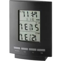
5.1 Base station (Receiver)
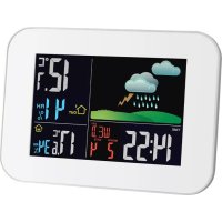
A: Display (Fig. 1):
Upper display
Indication of the indoor values
A 1: Symbol for indoor
A 2: Indoor temperature and humidity
A 3: Symbol for DST and DCF, time, weekday or seconds, date, optionally alarm time with alarm symbol
Lower display
Indication for the pool sensor
A 4: Symbol for pool sensor
A 5: Minimum water temperature with symbol, optionally symbol for alarm
A 6: Actual water temperature
A 7: Maximum water temperature with symbol, optionally symbol for alarm
A 8: CL 24 symbol for automatic reset of the maximum and minimum values
B: Buttons (Fig. 1):
B 1: MIN/MAXI- button B 2: ALARM/SET button
B 3: CHANNEL/+ button
C: Housing (Fig. 2):
C 1: Wall mounting hole C 2: Battery compartment
C 3: Stand (fold out)
5.2 Pool sensor (Fig. 3):
: Display:
D 1: Water temperature D 2: Channel number
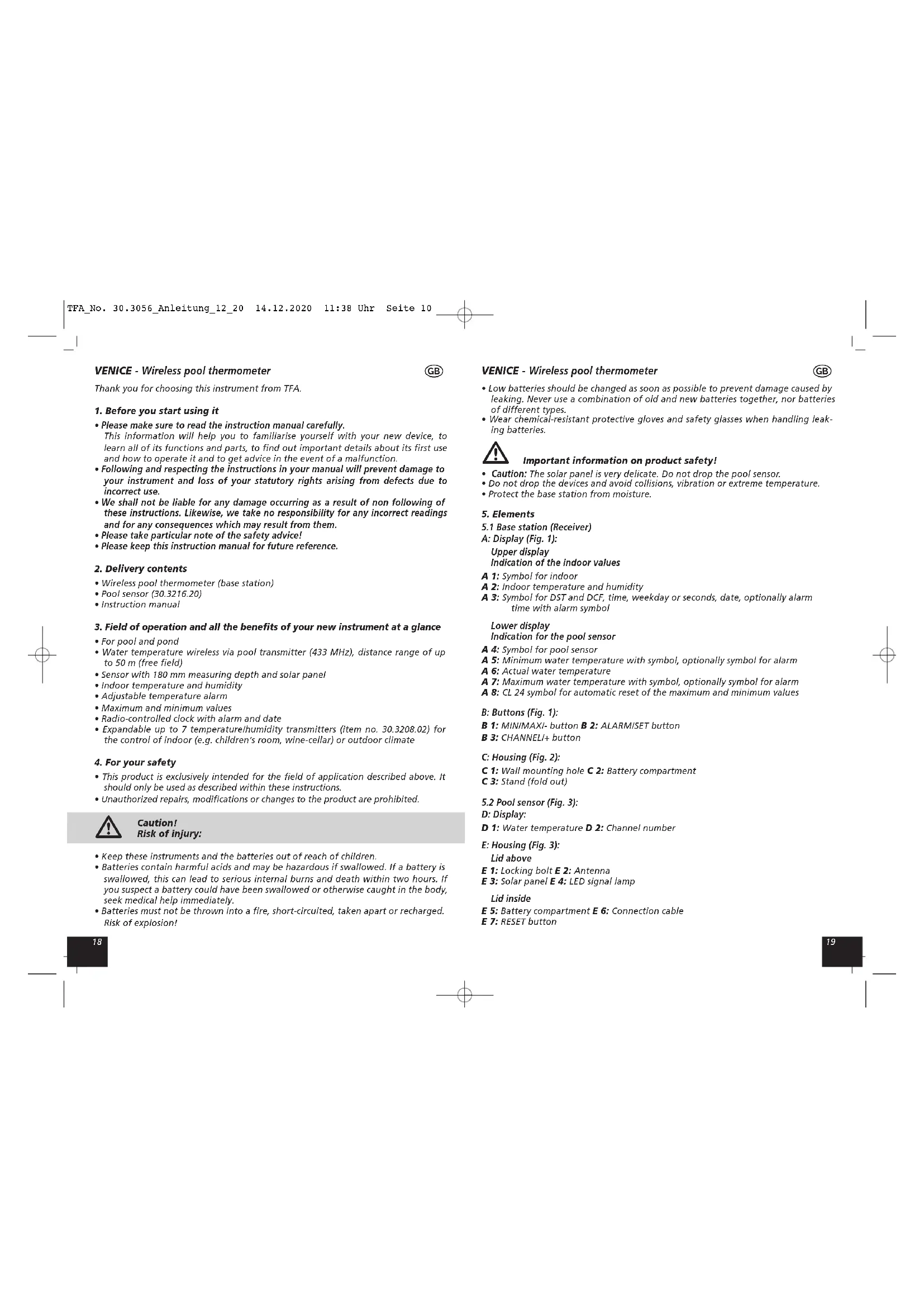
E: Housing (Fig. 3):
Lid above
E 1: Locking bolt E 2: Antenna
E 3: Solar panel E 4: LED signal lamp
Lid inside
E 5: Battery compartment E 6: Connection cable
E 7: RESET button
VENICE - Wireless pool thermometer

6. Getting started
6.1 Insert the batteries
- Place the instruments on a desk with a distance of approximately 1.5 meter. Avoid getting close to possible interference sources (Electronic devices and radio installations).
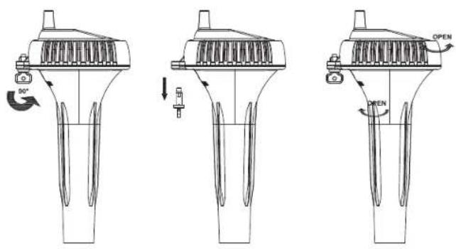
6.1.1 Installation of the pool sensor (Fig. 5)
- Turn the locking bolt 90^ and remove it.
- Turn the lid strongly in direction of the arrow (open), see page 78, fig. 5!
- Please pay attention to the connection cable when opening.
- Open the battery compartment of the pool sensor by lifting the battery compartment cover at the recess.
- Insert four new batteries 1,5 V AAA, polarity as illustrated.
• The LED signal lamp will be flashing. - On the display of the pool sensor appear the channel number 1 and the temperature in ^ C.
- Close the battery compartment and carefully screw the lid in direction of the arrow (close).
• Pay attention to the sealing ring. - Insert the locking bolt from the bottom side in the hole and lock the lid.
6.1.2 Installation of the base station
- Open the battery compartment and insert four new batteries 1.5 V AAA, polarity as illustrated.
• The device will alert you with a beep. - All LCD segments will be displayed briefly.
- On the upper display of the base station appear the indoor temperature and humidity.
- The pool sensor automatically uses channel number one and is displayed in the lower display. If the reception is successfully, on the display appear the water temperature with the maximum and minimum values.
- Close the battery compartment again.
6.2 Reception of the outdoor values
- After the batteries are inserted, the measuring values of the pool sensor will be transmitted to the base station. The LED signal lamp will be flashing. If the reception of the outdoor values fails, "-" appears on the display of the base station. Check the batteries and try it again. Check if there is any source of interference. Press the RESET button on the pool sensor.
- As soon as the base station received the radio-controlled time, you can start the initialization manually. Press and hold the CHANNEL/+ button for three seconds. A short beep will be heard and the base station will scan the outdoor values.
6.3 Reception of the DCF frequency signal
- The clock will now scan the DCF frequency signal and the DCF symbol will be flashing on the display. When the time code is received successfully after a few minutes, the radio-controlled time, the DCF symbol, optionally the Daylight Saving symbol and the date are displayed steadily on the display.
- The DCF reception always takes place every six hours.
VENICE - Wireless pool thermometer

• There are three different reception symbols:

flashing - reception is active
stays – reception is very good
No symbol – no reception / set time manually
- If the clock cannot detect the DCF-signal (for example due to disturbances, transmitting distance, etc.), the time can be set manually. The DCF symbol disappears and the clock will then work as a normal quartz clock. (see: Manual settings).
7. Note for radio-controlled time DCF
The time base for the radio-controlled time is a caesium atomic clock operated by the Physikalisch Technische Bundesanstalt Braunschweig. It has a time deviation of less than one second in one million years. The time is coded and transmitted from Mainflingen near Frankfurt via frequency signal DCF-77 (77.5 kHz) and has a transmitting range of approximately 1,500 km. Your radio-controlled clock receives this signal and converts it to show the precise time. Changeover from summer time or winter time is automatic. On the display appears a symbol during the Daylight Saving Time. The quality of the reception depends mainly on the geographic location. The quality of the reception depends mainly on the geographic location. Normally there should be no reception problems within a 1,500 km radius around Frankfurt.
Please take note of the following:
- The recommended distance to any interfering sources like computer monitors or TV sets is at least 1.5 - 2 meters.
- Inside ferro-concrete rooms (basements, superstructures), the received signal is naturally weakened. In extreme cases, please place the unit close to a window to improve the reception.
- During night-time, the atmospheric interference is usually less severe and reception is possible in most cases. A single daily reception is adequate to keep the accuracy deviation under 1 second.
8. Operation
- Attention: During the reception of the outdoor values and the radio-controlled time a button operation is not possible.
- Press and hold the MIN/MAXi- or CHANNEL/+ button in the respective setting mode for fast running.
- The device will automatically quit the setting mode if no button is pressed for a long period of time.
8.1 Manual settings
- Press and hold ALARM/SET button in normal mode.
• RCC appears on the display. - On (default) will be flashing and you can deactivate (OFF) the DCF reception with the MIN/MAX/- or CHANNEL/+ button.
- Press the ALARM/SET button to make the settings in the following sequence: Time zone (ZON - default OH), the 12 or 24 hours system (24 H - default), the hours, the minutes, the indication for the date (D-M default), the month, the day, the year and the possibility of the automatic reset of the maximum and minimum values (CLR - default ON). Press the MIN/MAXI- or CHANNEL/+ button to adjust it.
- Confirm the setting with the ALARM/SET button.
VENICE - Wireless pool thermometer

- The manually set time will be overwritten by the DCF time when the signal is received successfully and when the DCF reception is activated.
8.1.1 Setting of the time zone
- In the setting mode you can make the time zone correction (-12/+12).
- The time zone correction is needed for countries where the DCF signal can be received but the time zone is different from the German time (e.g. +1=one hour later).
• ZON appears on the display. - Press the MINIMAXI- or CHANNELI+ button.
8.1.2 Setting of the 12 or 24 hours display
- Press the MIN/MAX/- or CHANNEL/+ button in the setting mode to choose the 12 hours or 24 hours system.
- In the 12 hours system AM or PM (after 12 o'clock) appears on the display.
8.1.3 Setting of the date display
- Press the MIN/MAXI- or CHANNEL/+ button in the setting mode to choose the European date display (D-M first the day and then the month) or the American date display (M-D first the month and then the day).
8.1.4 Automatic reset of the maximum and minimum values
- In the setting mode you can activate or deactivate the automatic reset of the maximum and minimum values.
- CLR appears on the display and ON will be flashing.
- Press the MIN/MAX/- or CHANNEL/+ button to deactivate (OFF) or activate (ON) the automatic reset.
- If the automatic reset is activated the symbol CL24 appears on the display.
- The maximum and minimum values will be reset automatically every midnight at 0:00.
8.2 Maximum/Minimum function
- Press the MIN/MAXI-button.
• MAX appears on the display. - You can now read the highest value for the temperature and humidity for indoors. The highest water temperature remains on the display.
- Press the MIN/MAXI-button again.
• MIN appears on the display. - You can now read the lowest value for the temperature and humidity for indoors. The lowest water temperature remains on the display.
- Press the MINIMAXI-button again to return to normal mode.
8.2.1 Resetting the maximum and minimum values
8.2.1.1 Manual reset
- Press and hold the MIN/MAX/- button during the highest or lowest values are displayed. The values will be deleted and the values will be reset to the current state.
8.2.1.2 Automatic reset
- In the setting mode you can activate or deactivate the automatic reset of the maximum and minimum values (see: 8.1.4).
VENICE - Wireless pool thermometer

8.3 Display of seconds/weekday or date/year
• In normal mode on the display appear the time with seconds and the date.
- Press and hold the MINIMAXI-button for three seconds to change the display from seconds to weekday permanently.
- The indication of the year appears for 30 seconds. Afterwards the actual date will appear again.
8.4 Setting of the alarm
- In the alarm setting mode you can set a wake-up alarm and a Hillow-alarm for the pool sensor.
- Press the ALARM/SET button.
- ALM and 0:00 (default) or the last adjusted alarm time appear on the display. For the Hillow alarm 37,8/15,6 (default) or the last adjusted alarm limit appears.
8.4.1 Setting of the alarm time
- Press and hold the ALARM/SET button.
• The hour digits will be flashing - Press the MINIMAXI- or CHANNEL/+ button to adjust hours.
- Press the ALARM/SET button again and set minutes in the same way.
- Confirm the setting with the ALARM/SET button.
8.4.2 Setting of the alarm for the pool sensor
• The lower temperature limit will be flashing.
- Press the MINIMAXI- or CHANNEL/+ button to set the lower temperature limit.
- Press the ALARM/SET button again to set the higher temperature limit in the same way.
- Confirm the setting with the ALARM/SET button. Press the ALARM/SET button again to return to normal mode.
8.4.3 Activate the alarm
- To activate an alarm (alarm, Low-alarm, Hi-alarm), press and hold the ALARM/SET button for three seconds in the alarm setting mode while the corresponding value is flashing. If the alarm is activated, an alarm symbol appears beside the corresponding value.
- Deactivate the alarm value in the same way.
8.4.4 Case of alarm
• In the case of an alarm a beep will sound.
• The corresponding alarm symbol will be flashing.
- Press any button and the alarm will stop. The alarm setting remains active.
9. Positioning and fixing of the base station and the pool sensor
- With the foldable leg at the back of the base station it can be placed onto any flat surface or wall mounted at the respective location by the hanging hole at the back of the unit. Avoid the vicinity of any interfering field like computer monitors or TV sets and solid metal objects.
- The pool sensor floats on the water surface and measures the temperature in a water depth of about 180 mm. You can fix the pool sensor by a fastening rope. Pull the cord through the opening in the locking bolt (Fig. 4).
- With the solar panel the battery life of the pool sensor will be extended. The batteries are not charged.
VENICE - Wireless pool thermometer

- Check the transmission of the signal from the pool sensor to the base station (transmission range of up to 50 m in free field). In case of solid walls, especially with metal parts, the pool transmission range can be considerably reduced.
- If necessary choose another position for the base station.
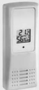
10. Additional transmitter (Cat.No. 30.3208.02) optionally available
- Beside the pool sensor, the base station is able to receive 7 additional transmitters for the control of indoor (e.g. children's room, wine-cellar etc.) or outdoor climate.
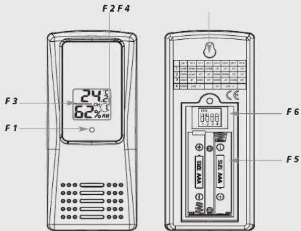
10.1 Elements Transmitter (Fig. 6):
Housing front:
F 1: Transmission signal lamp
Display:
F 2: Channel number
F 3: Temperature and humidity
Housing rear:
F 4: Wall mounting hole
F 5: Battery compartment
in the battery compartment:
F 6: Switch 1, 2, 3 and 4
10.2 Install the optional transmitters
- Open the screwed battery compartment of the transmitter.
- For the first transmitter (channel number two), slide down the first and the second switch and slide up the third switch.
- It is recommended to let the fourth switch permanently in the upper position, as the base station receives the temperature only in degrees Celsius ( ^ C).
- Insert two new batteries 1,5 V AAA, polarity as illustrated. On the display appear the measured temperature and humidity and the channel number 2.
- Channel number one is automatically reserved for the pool sensor.
- Close the battery compartment again.
- If you want to connect further transmitters, repeat the steps for channel number three until eight. The correct switch position for the transmitter 2-8 can be found in the table.
| Switch (F 6) | Function | |||
| 1 | 2 | 3 | 4 | |
| down down up | up CHANNEL 2 | |||
| down up down | up CHANNEL 3 | |||
| down up up | CHANNEL 4 | |||
| up down down | up CHANNEL 5 | |||
| up down up | CHANNEL 6 | |||
| up up down up | CHANNEL 7 | |||
| up up up up | CHANNEL 8 | |||
| — | — | — | u | p |
VENICE - Wireless pool thermometer

10.3 Reception of the transmitters by the base station
- The base station tries to receive the outdoor temperature and humidity values of the transmitters on channel number two until eight.
- You can also start the search for the transmitter manually. Choose the corresponding channel with the CHANNEL/+ button and press und hold the CHANNEL/+ button for three seconds. A short beep will be heard and the base station will scan the outdoor values.
- Press the CHANNEL/+ button on the base station to display sequentially the outdoor values for the desired transmitters. On the display appear the indoor values or the selected transmitter.
- Press the CHANNEL/+ button again after the last installed transmitter, on the display appears the circle symbol. On the upper display the values of the indoor sensor and the installed transmitters are displayed in sequence. To deactivate the function press the CHANNEL/+ button again.
- With the MINIMAXI- button you can recall the highest and lowest temperature and humidity values for all installed transmitters.
10.4 Positioning and fixing of the transmitters
- With the hanging hole at the back of the transmitter, the transmitter can be wall mounted at the respective location. Placed outside, choose a shady and dry position for the transmitter. (Direct sunshine falsifies the measurement and continuous humidity strains the electronic components needlessly).
11. Care and maintenance
- Clean the devices with a soft damp cloth. Do not use solvents or scouring agents.
- For a very good function keep the solar panel always clean. Clean the solar panel with a soft cloth and maybe a little glass- or display cleaner.
• After every battery replacement in the pool sensor, use a small amount of silicone grease for the seals. - Remove the batteries if you do not use the devices for a long period of time.
- Keep the devices in a dry place.
11.1 Battery replacement
- Change the batteries of the base station, when the battery symbol appears in the upper display beside the indoor temperature.
- Change the batteries of the pool sensor, when the battery symbol appears in the lower display beside the pool temperature.
- Change the batteries of the corresponding transmitter, when the battery symbol appears in the upper display beside the channel no. 2-8.
- Please note: When the batteries are changed, the contact between sensor and base station must be restored – so always insert new batteries into all units or start a manual transmitter search.
12. Troubleshooting
Problems Solution
No indication on the base → Ensure that the batteries' polarities are correct station/pool sensor → Change the batteries
VENICE - Wireless pool thermometer
GB
| No DCF reception → Activate DCF reception in the setting mode→ Press and hold the ALARM/SET button for three seconds and start the initialization manually→ Wait for attempted reception during the night→ Choose another place for the base station→ Manual setting of the clock→ Check if there is any source of interference.→ Restart the base station according to the manual | |
| No reception of the → No pool transmitter installedpool transmitter → Check the batteries of pool transmitterDisplay “- -” | (do not use rechargeable batteries!)→ Restart the pool transmitter and the base station according to the manual→ Start the manual search for the pool transmitter:Press and hold the CHANNEL/+ button on the base station→ Press the RESET button of the pool transmitter→ Choose another place for the base station→ Reduce the distance between the pool transmitter and the base station→ Check if there is any source of interference |
| No transmitter receptionDisplay “- -” | → No transmitter installed→ Check batteries of transmitter(do not use rechargeable batteries!)→ Restart the outdoor transmitter and the base station according to the manual→ Manual search for the transmitter according to the manual→ Choose another place for the transmitter and/or the base station→ Reduce the distance between the transmitter and the base station→ Check if there is any source of interference |
| Incorrect indication | → Change the batteries→ Use the calibration function |
If your device fails to work despite these measures contact the supplier from whom you purchased it.
13. Calibration function
- The radio-controlled pool thermometer allows the user to calibrate the display of temperature and humidity measurements on the base station with an external, better reference source. The user can make adjustments to the temperature and humidity displays within the measuring range.
13.1 Calibration of the temperature
- Press and hold at the same time the ALARM/SET and the CHANNEL/+ button for five seconds.
• The indoor temperature will be flashing. - Press the MIN/MAX/- or CHANNEL/+ button to adjust the indoor temperature.
VENICE - Wireless pool thermometer
GB
- Press the ALARMISET button and you can adjust the pool temperature and the outdoor temperature for the optional installed transmitters with the MINIMAXI-or CHANNEL/+ button.
- Press and hold the ALARM/SET button while the indoor or the outdoor temperature is flashing and the previous, unchanged value is displayed again.
- Confirm the setting with the ALARM/SET button.
13.2 Calibration of the humidity
- Press the ALARM/SET and the MIN/MAXI-button at the same time for five seconds.
- The indoor humidity will be flashing.
- Press the MINIMAXI- or CHANNEL/+ button to adjust the indoor humidity
- Press the ALARM/SET button and you can adjust the outdoor humidity for the optional installed transmitters with the MIN/MAX/- or CHANNEL/+ button.
- Press and hold the ALARM/SET button while the indoor or the outdoor humidity is flashing and the previous, unchanged value is displayed again.
- Confirm the setting with the ALARM/SET button.
14. Waste disposal
This product has been manufactured using high-grade materials and components which can be recycled and reused.
 | Never dispose of empty batteries and rechargeable batteries in house-hold waste. As a consumer, you are legally required to take them to your retail store or to an appropriate collection site depending on national or local regulations in order to protect the environment.The symbols for the heavy metals contained are:Cd=cadmium, Hg = mercury, Pb=leadThis instrument is labelled in accordance with the EU Waste Electrical and Electronic Equipment Directive (WEEE).Please do not dispose of this instrument in household waste. The user is obligated to take end-of-life devices to a designated collection point for the disposal of electrical and electronic equipment, in order to ensure environmentally-compatible disposal. |
15. Specifications
Base station:
| Measuring range indoorsTemperature 0°C... +60°C |
Resolution 0,1°C
Accuracy ±1°C
Humidity 20 ... 99 %
Resolution 1%
Accuracy ±5% (between 20...90%)
Power consumption Batteries 4 x 1,5 V AAA (not included) Use alkaline batteries
Dimensions 116 x 24 (65) x 126 mm
Weight 160 g (instrument only)
VENICE - Wireless pool thermometer
GB
Pool transmitter:
| Water temperature -40 ... +60°C |
| Resolution 0,1°C |
| Accuracy ±1°C |
| Measuring depth 180 mm |
| Range ca. 50 m (free field) |
| Transmission frequency 433 MHz |
| Maximumradio-frequency power < 10mW |
| Power consumption Batteries 4 x 1,5 V AAA (not included)Use alkaline batteries |
| Dimensions 95 x 106 x 220 mm |
| Weight 290 g (instrument only) |
Optional outdoor transmitter (not included):
| Measuring range outdoors Temperature -40 ... +60 °C | |
| Accuracy ±1°C | |
| Resolution 0,1°C | |
| Humidity | 10 ... 99% |
| Resolution 1 % | |
| Range max. 100 m (free field) | |
| Transmission frequency 433 MHz | |
| Maximum radio-frequency power < 10mW | |
| Power consumption 2 x 1,5 V AAA (batteries not included) Use alkaline batteries | |
| Dimensions 45 x 20 x 110 mm | |
| Weight 52 g (instrument only) | |
No part of this manual may be reproduced without written consent of TFA Dostmann. The technical data are correct at the time of going to print and may change without prior notice. The latest technical data and information about this product can be found in our homepage by simply entering the product number in the search box.
EU DECLARATION OF CONFORMITY
Hereby, TFA Dostmann declares that the radio equipment type 30.3056 is in compliance with Directive 2014/53/EU. The full text of the EU declaration of conformity is available at the following Internet address: www.tfa-dostmann.de/service/downloads/sce
www.tfa-dostmann.de
DÉCLARATION UE DE CONFORMITÉ
Precisione ±5% (@ 20...90%)
Precisie ±5% (@ 20...90%)
The image is too blurry to recognize any text content.
Fig. 5
text_image
Technical diagram illustrating three stages of a mechanical device with 90° rotation and open states labeled 'OPEN'.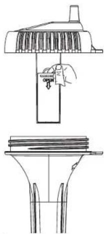
natural_image
Technical line drawing of a mechanical assembly with a handle and base, showing no text or symbols.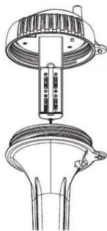
natural_image
Technical line drawing of a mechanical device with a top component and base, showing internal components without any text or symbols.Fig. 6
Zusätzlicher Sender (Kat.Nr.: 30.3208.02), optional erhältlich Additional transmitter (Cat.No. 30.3208.02) optionally available Émetteur supplémentaire (n° de l'art. 30.3208.02), disponible en option Trasmettitore supplementare (Cat. n. 30.3208.02), disponibile come optional Extra zender (cat. nr. 30.3208.02), verkrijgbaar als optie Emisor adicional (no. de cat. 30.3208.02), disponible como opción
text_image
F2 F4 F3 62% F1 F6 F5