DMT4010RMS - Multimeter Monacor - Free user manual and instructions
Find the device manual for free DMT4010RMS Monacor in PDF.
| Product type | Professional digital multimeter |
| Brand | Monacor |
| Model | DMT4010RMS |
| Display | LCD 3 3/4 digits (4000 counts), 41-segment bar graph |
| True RMS measurement | Yes (for AC voltage and current) |
| Measurement category | CAT III 1000 V, CAT IV 600 V |
| Maximum voltage | 1000 V DC/AC |
| Maximum current | 10 A (with 10 A H/1000 V fuse) |
| Maximum resistance | 40 MΩ |
| Maximum capacitance | 40 mF |
| Maximum frequency | 10 MHz |
| Temperature range | -20 °C to +760 °C (type K probe) |
| Continuity test | Built-in buzzer, threshold < 35 Ω |
| Diode test | Forward voltage up to 1.999 V |
| Enclosure protection rating | IP67 (dust-tight and temporary immersion) |
| Power supply | 1 9 V battery (not included) |
| Dimensions (W × H × D) | 85 × 180 × 54 mm |
| Weight | 430 g |
| Operating temperature range | -10 °C to +50 °C |
| Operating relative humidity | < 70% |
| Additional functions | Manual range selection, value hold (HOLD), MAX/MIN, peak display (PEAK), display illumination |
| Supplied accessories | Red and black test leads, type K temperature probe, multilingual stickers, isolation caps |
| Maintenance and cleaning | Clean the housing with a dry or slightly damp cloth, without chemicals |
| Spare parts and repairability | 9 V battery replaceable by user; fuses (F 10 A H/1000 V and F 500 mA H/1000 V) replaceable by qualified technician |
| General information | Auto power off after 30 min; outdoor use possible thanks to IP67 |
Frequently Asked Questions - DMT4010RMS Monacor
User questions about DMT4010RMS Monacor
0 question about this device. Answer the ones you know or ask your own.
Ask a new question about this device
Download the instructions for your Multimeter in PDF format for free! Find your manual DMT4010RMS - Monacor and take your electronic device back in hand. On this page are published all the documents necessary for the use of your device. DMT4010RMS by Monacor.
USER MANUAL DMT4010RMS Monacor
GB Before you switch on ...
We hope you will enjoy using your new MONACOR unit. Please read these operating instructions carefully prior to operation and keep them for later reference.
The English text starts on page 12.
natural_image
Two identical cylindrical objects with rounded tops, one labeled with the number 13 (no text or symbols on the objects themselves)Inhalt
1 Operating Elements and Connections 12
2 Safety Notes 13
3 Applications 13
4 Attaching the Label ..... 13
5 Operation 13
5.1 Connecting the test leads ..... 14
6 Measuring 14
6.1 Measuring voltages ..... 14
6.2 Measuring currents ..... 14
6.3 Measuring resistances ..... 15
6.4 Testing the continuity ..... 15
6.5 Testing diodes 15
6.6 Measuring capacitances ..... 15
6.7 Measuring frequencies ..... 16
6.8 Measuring temperatures ..... 16
7 Additional Functions ..... 16
7.1 Manual range selection ..... 16
7.2 Data hold function ..... 16
7.3 Indicating the maximum / minimum value ..... 16
7.4 Indicating short peaks ..... 17
8 Inserting a New Battery or Replacing Fuses .... 17
8.1 Inserting a battery ..... 17
8.2 Replacing fuses ..... 17
9 Specifications 18
All operating elements and connections described can be found on the fold-out page 3.
1 Operating Elements and Connections
1 Button "RANGE" for manual range selection
2 Button "HOLD" to hold a measured value
3 Button "MODE" to switch the measuring mode (e. g. DC or AC voltage measurement, temperature measurement in Celsius or Fahrenheit)
4 Jack "10A" for the red test lead for measuring currents up to 10 A max.
5 Jack “μA/mA” for the red test lead for measuring currents up to 400 mA max.
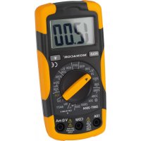
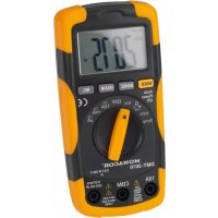
6 LC display with 3^3/4 -digit digital indication and bar graph
7 Button "PEAK" to indicate short peak values when measuring voltages and currents
8 Button "MAX / MIN" to indicate the maximum value and minimum value during a measurement
9 Button for the display illumination
10 Selector switch for the measuring functions
11 Jack "V Hz Ω CAP °C °F" for the red test lead when measuring voltages, frequencies, resistances and capacitances; when measuring temperatures, connect the positive pole of the type K temperature sensor to this jack
12 Jack "COM" for the black test lead or, when measuring temperatures, for the negative pole of the type K temperature sensor
13 Sleeves to seal the two red jacks not used to ensure protection of the meter according to IP 67 (e. g. to protect it against humidity for outdoor applications)
2 Safety Notes
The meter corresponds to all required directives of the EU and is therefore marked with €€
WARNING With this meter, dangerous voltages can be measured. Particular attention should be paid when measuring voltages equal to or higher than 42 V!
- Wear protective gloves to protect yourself against electric shock.
- When applying the test tips, make sure that your fingers will be protected behind the collars of the tips.
- Never perform any measurements when the meter or the test leads are damaged. Always replace damaged test leads by original test leads.
Please observe the following items in any case:
- If the sleeves (13) are used, the meter will be protected according to IP 67 and will also be suitable for outdoor applications. However, protect the meter against extreme temperatures (admissible ambient temperature range -10^ to +50^ ).
- For cleaning the housing, only use a soft cloth, slightly wet, if necessary; never use chemicals or abrasive detergents.
- No guarantee claims for the unit and no liability for any resulting personal damage or material damage will be accepted if the relevant safety regulations for handling voltages equal to or higher than 42 V are not observed, if the meter is used for other purposes than originally intended, if it is not correctly connected or operated, if it is overloaded or not repaired in an expert way.
If the meter is to be put out of operation definitively, take it to a local recycling plant for a disposal which is not harmful to the environment.
3 Applications

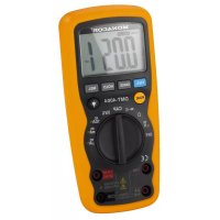
This digital multimeter DMT-4010RMS with automatic range selection is suited for professional applications. It features True RMS measurement to ensure accurate measuring results even in case of non-sinusoidal or distorted signal waveforms. Due to its weatherproof housing (IP 67 protection), it is suited for outdoor applications.
The meter will measure voltages up to 1000 V/\~, currents up to 10 A/\~, frequencies up to 10 MHz, resistances up to 40 MΩ, capacitances up to 40 mF and temperatures from -20 °C to +760 °C. It will also test diodes. A buzzer is provided for testing the continuity,
4 Attaching the Label
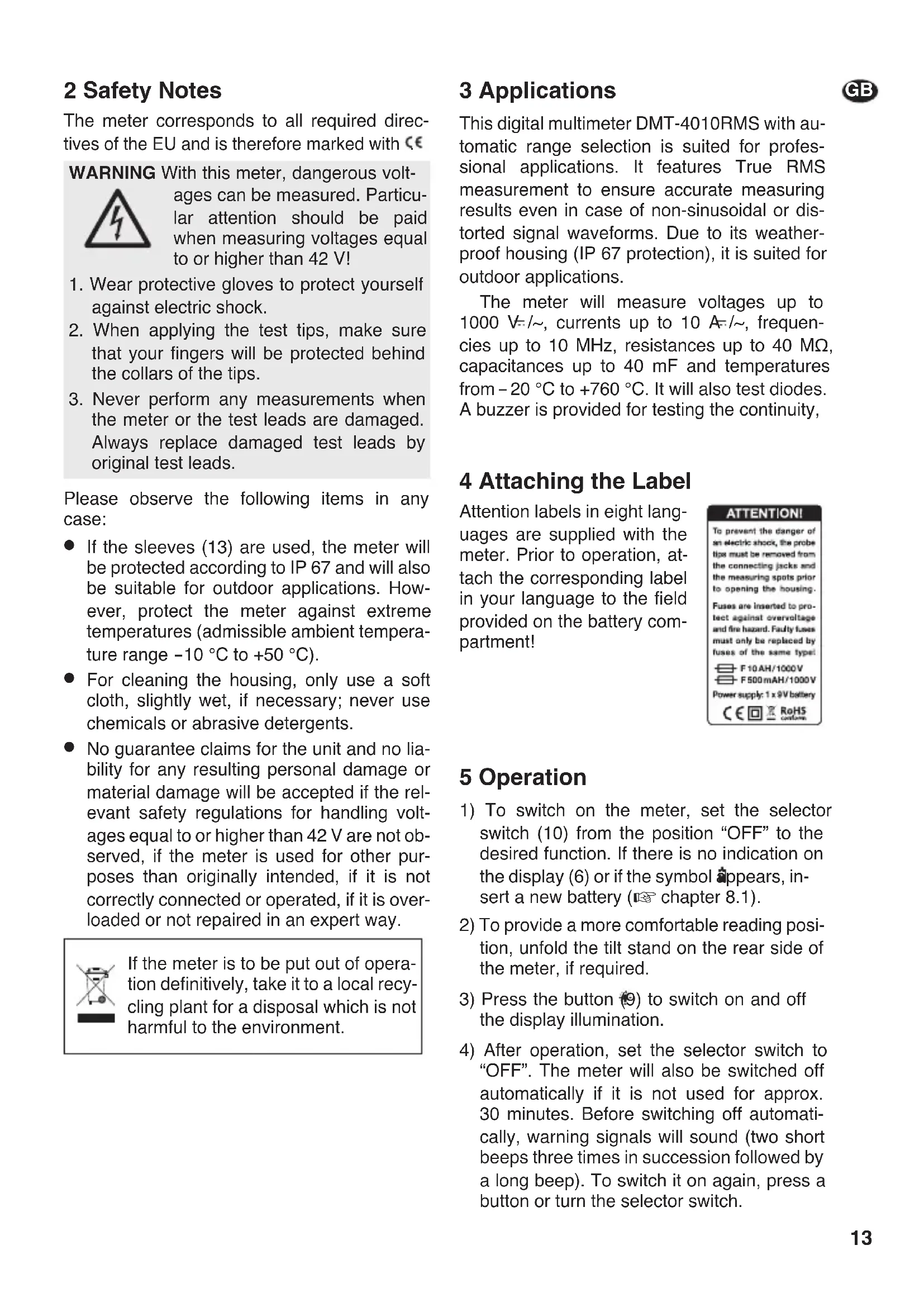
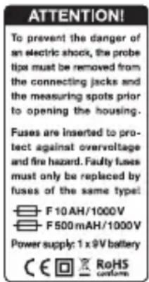
Attention labels in eight languages are supplied with the meter. Prior to operation, attach the corresponding label in your language to the field provided on the battery compartment!
text_image
ATTENTION! To prevent the danger of an electric shock, the probe tips must be removed from the connecting jacks and the measuring spots prior to opening the housing. Fuses are inserted to pro- tect against overvoltage and fire hazard. Faulty fuses must only be replaced by fuses of the same type: F 10 AH/1000V F 500 mAH/1000V Power supply: 1 x 9V battery € 📋 RoHS custom5 Operation
1) To switch on the meter, set the selector switch (10) from the position "OFF" to the desired function. If there is no indication on the display (6) or if the symbol appears, insert a new battery (chapter 8.1).
2) To provide a more comfortable reading position, unfold the tilt stand on the rear side of the meter, if required.
3) Press the button (9) to switch on and off the display illumination.
4) After operation, set the selector switch to "OFF". The meter will also be switched off automatically if it is not used for approx. 30 minutes. Before switching off automatically, warning signals will sound (two short beeps three times in succession followed by a long beep). To switch it on again, press a button or turn the selector switch.
If the meter is not used for a longer period, it is recommended to remove the battery to prevent any damage to the meter due to battery leakage.
5.1 Connecting the test leads
The meter is supplied with two test leads (red and black). They will allow to perform all measurements except for temperature measurements (chapter 6.8):
- The jack "COM" (12) is the common (-) jack for all measurements. Connect the black test lead to this jack.
- The jack "V Hz Ω CAP °C °F" (11) is the common (+) jack for all measurements, except for measuring currents. Connect the red test lead to this jack.
- For measuring currents up to 400 mA, connect the red test lead to the jack “ A/mA” (5).
- For measuring currents between 400 mA and 10 A, connect the red test lead to the jack "10A" (4).
For measuring, remove the protective caps from the test tips and replace them after use.
IMPORTANT! To ensure protection of the meter according to IP 67 (e. g. to protect it against humidity for outdoor applications), insert the sleeves (13) provided into the two red jacks not used.
6 Measuring
WARNING
Measurements in circuits carrying more than 42 V must only be made by persons able to recognize a hazard of contact and to take the required safety precautions. In case of measurements with a hazard of contact, avoid working on your own. Ask a second person to assist.
Caution: Before switching to another measuring function, always remove the test tips from the object to be measured to prevent damage to the meter!
6.1 Measuring voltages
WARNING
Take into account unexpected voltages on objects to be measured. Capacitors, for example, may be dangerously charged even if the voltage source has been switched off.
- Never use this meter for measuring circuits with corona discharges (high voltage). Risk of electrocution!
- The maximum voltage to be measured must not exceed 1000 V=\~/\~, otherwise you will risk your life!
Caution: Connect the red test lead to the jack "V Hz Ω CAP °C °F" (11). If it is connected to the jack "10A" (4) or "μA/mA" (5), the meter and the object to be measured may be damaged!
1) Set the selector switch (10) to the position "V≡" to activate the mode "DC voltage measurement" ("DC" will be displayed).
2) For AC voltage measurements, press the button "MODE" (3) ["AC" will be displayed]. To return to "DC", press the button "MODE" again.
3) Apply the test tips to the object to be measured and read the value on the display. If the red test tip is applied to the negative pole and the black tip to the positive pole when measuring DC voltages, there will be a minus sign in front of the value displayed.
6.2 Measuring currents
- The current to be measured must not exceed 10 A!
1) For measurements up to 400 mA, connect the red test lead to the jack “ A/mA” (5); for measurements up to 10 A, connect it to the jack “10A” (4). With unknown currents, start with the 10 A range to be on the safe side.
2) According to the intensity of current, set the selector switch (10) to the following position:
up to 4000 μA position “μA” ≈
4000 μA to 400 mA position “mA” ≈ 400 mA to 10 A position “10A” ≈
The mode “DC current measurement” will be activated (“DC” will be displayed).
3) For AC current measurements, press the button "MODE" (3) ["AC" will be displayed].
To return to "DC", press the button "MODE" again.
4) Insert the meter via the test leads into the circuit to be measured and read the value on the display. If the red test tip is applied to the negative pole and the black tip to the positive pole when measuring DC currents, there will be a minus sign in front of the value displayed.
If the current measured exceeds the admissible value of a measuring range, warning signals will sound and "OL" (overload) will be displayed. In this case, select the next higher range.
6.3 Measuring resistances
- Never measure a resistor when voltage is applied; always measure it separately, otherwise the measurement will be inaccurate. For this purpose, it may be necessary to solder it out of the circuit.
1) Set the selector switch (10) to the position "Ω → to activate the mode "resistance measurement".
2) Apply the test tips to the resistor and read the value on the display. As long as the resistance value between the test tips is >40 MΩ, “OL” will be displayed to indicate that the measuring range has been exceeded.
6.4 Testing the continuity
- Never test the continuity when voltage is applied, otherwise the measurement will be inaccurate.
The continuity buzzer will help to detect interruptions in the circuit.
1) Set the selector switch (10) to the position "Ω # to activate the mode "resistance measurement".
2) To switch to continuity test, press the button "MODE" (3) once (buzzer symbol will be displayed).
3) Apply the test tips to the measuring points. If the resistance value between the points is smaller than 35 , the internal buzzer will sound. The resistance value will be displayed up to 400 . With higher values, the overload indication “OL” will appear.
6.5 Testing diodes
- Never test a diode when voltage is applied; always test it separately, otherwise the measurement will be inaccurate. For this purpose, it may be necessary to solder the diode out of the circuit.
1) Set the selector switch (10) to the position "Ω → to activate the mode "resistance measurement".
2) To switch to diode test, press the button "MODE" (3) twice (diode symbol will be displayed).
3) Apply the black test tip to the cathode of the diode and the red test tip to the anode. With a measurement current of approx. 1 mA, a forward voltage up to 1.999 V will be displayed. If a value around 0 V is displayed, the diode has a short circuit. If “OL” is displayed, the diode is interrupted, reverse-biased (reverse the polarity of the diode) or has a higher forward voltage (e.g. some LEDs).
6.6 Measuring capacitances
WARNING
Never measure a capacitor when it is charged or when operating voltage is applied; otherwise you will risk an electric shock.
Switch off the power supply and discharge the capacitor before soldering it out of the circuit.
1) Set the selector switch (10) to the position "CAP".
2) Apply the test tips to the capacitor. With electrolytic capacitors, observe the polarity: Apply the red test tip to the positive pole, apply the black test tip to the negative pole.
Read the value on the display. With very high capacitances, the measuring process will require some time. It may take a few minutes before the reading on the display has stabilized. When measuring capacitances, the bar graph will have no function.
Note: If the display shows “diS.C”, the capacitor is charged and must be discharged before measuring. Due to the long discharge time, it is not recommended to discharge the capacitor via the multimeter.

6.7 Measuring frequencies
1) Set the selector switch (10) to the position "Hz".
2) Apply the test tips to the measuring points like for measuring voltages.
3) Read the frequency on the display.
6.8 Measuring temperatures
For measuring the surface temperature of objects, the meter is supplied with a type K temperature sensor with banana adapter plug. The temperature measurement is not suitable for medical purposes!
WARNING
To avoid electric shock, do not apply the temperature sensor to any objects carrying voltage.
1) Connect the sensor to the multimeter via the adapter plug: Connect the positive pole to the jack "V Hz Ω CAP °C °F" (11) and the negative pole to the jack "COM" (12).
To ensure protection of the meter according to IP 67 (e.g. to protect it against humidity for outdoor applications), insert the sleeves (13) provided into the two red jacks not used.
2) Set the selector switch (10) to the position “°C • °F”. After switching on, the mode “Fahrenheit” will be activated (“°F” will be displayed).
3) To switch to Celsius, press the button "MODE" (3) ["°C" will be displayed]. To return to "°F", press the button "MODE" again.
4) Apply the sensor to the object to be measured.
5) Once the reading has stabilized (after approx. 30 seconds), read the temperature on the display.
7 Additional Functions
7.1 Manual range selection
The optimum range for a measuring function will always be selected automatically when "AUTO" is displayed.
1) To hold a range selected automatically, press the button "RANGE" (1). "AUTO" will disappear and "MANU" will appear.
2) Each time the button "RANGE" is pressed, the next higher range will be selected. This will reduce the resolution of the measured value, but it will prevent permanent switching if the measured value fluctuates between two ranges.
When the highest possible range has been reached and the button is pressed again, the smallest range will be selected. If the range is too small, "OL" (overload) will be displayed. When measuring voltages and currents, warning signals will sound additionally.
3) To return to automatic range selection, keep the button "RANGE" pressed for approx. 2 seconds until "AUTO" appears instead of "MANU".
7.2 Data hold function
To hold a measured value on the display (e.g. to be able to read the value more easily when the test tips have been removed from the object to be measured), press the button "HOLD" (2). The digital display will hold the measured value, "HOLD" will appear and the automatic range selection will be deactivated ("MANU" will be displayed).
To deactivate the data hold function, press the button "HOLD". "HOLD" will disappear and the automatic range selection will be reactivated ("AUTO" will be displayed).
7.3 Indicating the maximum/minimum value
With the MAX/MIN function activated, the meter will record the maximum value and minimum value of a measurement and indicate them on the display. To activate this function, press the button "MAX / MIN" (8). The automatic range selection will be deactivated ("MANU" will be displayed). The button "MAX/MIN" will allow to switch between three indications:
- "MAX": The digital display will show the maximum value measured since the function has been activated. If a higher value is reached while measuring, the indication will be updated accordingly.
- "MIN": The digital display will show the minimum value measured since the function has been activated. If a lower value is
reached while measuring, the indication will be updated accordingly.
- "MAX/MIN" (flashing): The digital display will show the present reading.
To deactivate this function, keep the button "MAX/MIN" pressed for approx. 2 seconds. The automatic range selection will be reactivated ("AUTO" will be displayed).
To reset the values in order to perform a new MIN/MAX measurement, deactivate and reactivate the function.
7.4 Indicating short peaks
When measuring voltages (=/\~) and currents (=/\~), the PEAK function will allow to indicate peak values occurring too shortly to be recorded during the MAX/MIN measurement (chapter 7.3), e.g. short interfering pulses. It will be possible to measure peaks of a duration ≥ 1 ms.
1) When measuring voltages or currents, wait until the reading on the display has stabilized.
2) Keep the button "PEAK" (7) pressed until "CAL." is displayed: A calibration will be performed.
3) After calibrating, press the button "PEAK". The digital display will indicate the positive peak value of the measurement ("PMAX"). The automatic range selection will be deactivated ("MANU" will be displayed).
When the button “PEAK” is pressed again, the indication will change to the negative peak value of the measurement (“PMIN”).
If a higher or lower peak value is reached while measuring, the corresponding indication will be updated.
4) Use the button "PEAK" to switch between "PMAX" and "PMIN".
5) To deactivate this function, keep the button pressed for approx. 2 seconds until "PMAX" or "PMIN" disappears. The automatic range selection will be reactivated ("AUTO" will be displayed).
Note: If you select another measuring function with the selector switch (10) after calibrating, repeat the calibration for the new measuring function.
8 Inserting a New Battery or Replacing Fuses
WARNING
Before opening the housing, remove the test tips from the measuring points and the test leads from the jacks on the meter, otherwise you will risk an electric shock. Never operate the meter when it is open.
8.1 Inserting a battery
If nothing is displayed or if the symbol I = low battery) is displayed, insert a new 9 V battery.
1) Fold up the tilt stand on the rear side of the meter and release the two central screws of the battery compartment cover.
2) Remove the cover and insert a 9 V battery as indicated in the compartment.
3) Close the battery compartment and fasten the battery compartment cover.

Used batteries must not be placed in the household waste, always take them to a special waste disposal, e. g. collection container at your retailer.
8.2 Replacing fuses
If it is not possible to measure currents, check the internal fuses and have them replaced by qualified personnel.
1) On the rear side of the meter, release the six outer screws (two screws are situated under the tilt stand) and remove the rear housing shell.
2) Replace defective fuses by fuses of the same type only:
μA and mA range: F 500 mAH/1000 V 10 A range: F 10 AH/1000 V
3) Reassemble the housing shells and tightly fasten the screws.
GB 9 Specifications
LC display: ..... 21 mm digital display, 3 ^3 /4 digits (4000 counts), 41-segment bar graph
Measuring rate: ..... 2 measurements per second
Measuring category: . CAT III 1000 V and CAT IV 600 V
Overload indication: .. "OL" displayed
Voltage measurement, current measurement, resistance measurement, capacity measurement and frequency measurement 📋 table on the right
Temperature measurement
Temperature sensor: type K
Range: ..... -20 °C to +760 °C/-4 °F to +1400 °F
Resolution: 1^/1^
Accuracy: . . . . . . . . Celsius: ±(3 % + 5 digits), Fahrenheit: ±(3 % + 9 digits)
Overload protection: 1000 V=/\~
Continuity buzzer
Response threshold: < 35 Ω
Measurement
current: 1.5 mA max.
Overload protection: 1000 V=/\~
Diode test
Indication: ..... forward voltage up to 1.999 V
Accuracy: ±(10% + 5 digits)
Measurement
current: 1 mA approx.
Max. measurement
voltage: 3 V=
Overload protection: 1000 V=/\~
Protection class
of housing: ..... IP 67
Power supply: ..... 9 V battery (not supplied)
Operating conditions: . -10 °C to +50 °C, relative humidity < 70 %
Dimensions: 85 × 180 × 54 mm
Weight: 430 g
All accuracy values apply to the operating temperature range of 18 – 28 °C at a relative humidity < 70 %.
Subject to technical modification.
| Voltage/Current/Resistance/Capacitance/Frequency | |||
| Function Range Resolution Accuracy | |||
| DC voltageInput impedance 7.8 MΩOverload protection 1000 V=/~ | 400 mV 0.1 mV | ±(0.5% + 2 digits) | |
| 4 V 1 mV | |||
| 40 V 10 mV | |||
| 400 V 100 mV | |||
| 1000 V 1 V ±(0.8% + 2 digits) | |||
| AC voltageInput impedance 7.8 MΩTrue RMS measurement, 50 – 60 HzOverload protection 1000 V=/~ | 400 mV 0.1 mV | ±(0.8% + 3 digits) | |
| 4 V 1 mV | |||
| 40 V 10 mV | |||
| 400 V 100 mV | |||
| 1000 V 1 V ±(1.2% + 5 digits) | |||
| DC currentFuse: μA/mA range F 500 mAH/1000 V10Arange F10 AH/1000 V | 400 μA 0.1 μA | ±(1.2% + 3 digits) | |
| 4000 μA | 1 μA | ||
| 40 mA | 10 μA | ||
| 400 mA 100 μA | |||
| 10 A 10 mA | ±(2.5% + 3 digits) | ||
| AC currentTrue RMS measurement, 50 – 60 HzFuse: μA/mA range F 500 mAH/1000 V10 A range F 10 AH/1000 V | 400 μA 0.1 μA | ±(1.5% + 5 digits) | |
| 4000 μA | 1 μA | ||
| 40 mA | 10 μA | ||
| 400 mA 100 μA | |||
| 10 A 10 mA | ±(3.0% + 5 digits) | ||
| ResistanceOverload protection 1000 V=/~ | 400 Ω | 0.1 Ω | ±(0.8% + 5 digits) |
| 4 kΩ | 1 Ω | ±(0.8% + 2 digits) | |
| 40 kΩ | 10 Ω | ||
| 400 kΩ | 100 Ω | ||
| 4 MΩ 1 kΩ | ±(2.5% + 8 digits) | ||
| 40 MΩ | 10 kΩ | ||
| CapacitanceOverload protection 1000 V=/~ | 4 nF | 1 pF | ±(5.0% + 20 digits) |
| 40 nF | 10 pF | ±(5.0% + 7 digits) | |
| 400 nF | 0.1 nF | ±(3.0% + 5 digits) | |
| 4 μF 1nF | |||
| 40 μF 10 nF | |||
| 400 μF 0.1 μF | |||
| 4 mF | 0.001 mF | ±(10% + 10 digits) | |
| 40 mF | 10 mF | ||
| Frequency≤ 1 MHz: sensitivity > 0,5 V> 1 MHz: sensitivity > 3 VOverload protection 1000 V=/~ | 4 kHz | 1Hz | ±(1.2% + 3 digits) |
| 40 kHz | 10 Hz | ||
| 400 kHz | 100 Hz | ||
| 10 MHz 1 kHz | ±(1.5% + 4 digits) | ||
All rights reserved by MONACOR® INTERNATIONAL GmbH & Co. KG. No part of this instruction manual may be reproduced in any form or by any means for any commercial use.