DMT2004 - Multimeter Monacor - Free user manual and instructions
Find the device manual for free DMT2004 Monacor in PDF.

| Product type | Digital multimeter |
| Brand | Monacor |
| Model | DMT2004 |
| Display | LCD 3 ½ digits, 21 mm height |
| DC voltage measurement | 200 mV to 600 V, 5 ranges |
| AC voltage measurement | 200 V and 600 V, 2 ranges |
| DC current measurement | 2000 μA to 10 A, 4 ranges |
| Resistance measurement | 200 Ω to 2 MΩ, 5 ranges |
| Continuity test | Yes, with buzzer (threshold < 20 Ω) |
| Diode test | Yes, displays forward voltage up to 1.999 V |
| Battery test | 1.5 V and 9 V |
| HOLD function | Yes, holds displayed value |
| Display backlight | Yes, press button to activate |
| Measurement category | CAT III 250 V |
| Fuses | F 200 mAL/250 V (up to 200 mA) and F 10 AL/250 V (200 mA to 10 A) |
| Power supply | 1 9V battery (not included) |
| Dimensions | 68 × 138 × 37 mm |
| Weight | 200 g |
| Operating temperature | 0 °C to 50 °C |
| Relative humidity | < 70% |
| Maintenance and cleaning | Dry soft cloth, no chemicals or water |
| Safety | Do not use if damaged, replace fuses with same type, caution voltages > 42 V |
| Spare parts and repairability | Fuses and battery replaceable; other repairs by qualified technician |
Frequently Asked Questions - DMT2004 Monacor
User questions about DMT2004 Monacor
0 question about this device. Answer the ones you know or ask your own.
Ask a new question about this device
Download the instructions for your Multimeter in PDF format for free! Find your manual DMT2004 - Monacor and take your electronic device back in hand. On this page are published all the documents necessary for the use of your device. DMT2004 by Monacor.
USER MANUAL DMT2004 Monacor
Digitalmultimeter Digital Multimeter

text_image
MONACOR WWW.MONACOR.COM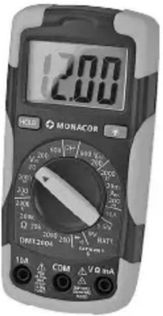
text_image
12.00 HOLD MONACOR VCC 200 600 400 V 200 200 200 200 200 200 200 200 200 Ω 75k 3.5V DMT2004 200 200 100 RATT 1mA COM VQ mADMT-2004
English ...... Page 12
Français....Page 20
Italiano ...... Pagina 28
These instructions are intended for persons with basic electrical knowledge. Please read the instructions carefully prior to operation and keep them for later reference.
Contents
1 Operating Elements and Connections ..... 12
2 Safety Notes 13
3 Applications 14
4 Operation 14
4.1 Connecting the test leads. 14
5 Measuring 15
5.1 Measuring voltages ..... 15
5.2 Measuring DC currents 16
5.3 Measuring resistances. 16
5.4 Testing the continuity. 16
5.5 Testing diodes ..... 17
5.6 Testing batteries 17
5.7 Data hold function 17
5.8 Activating the display illumination ..... 17
6 Replacing the Battery or the Fuses ..... 18
7 Specifications 18
All operating elements and connections described can be found on page 2.
1 Operating Elements and Connections
1 LC display
2 Button "HOLD" to hold a measured value
3 Button 📷 to activate /deactivate the display illumination
4 Selector switch for the measuring functions
5 Jack "10A" for the red test lead for measuring DC currents exceeding 200 mA to 10 A max.
6 Jack "V Ω mA" for the red test lead for all measurements, except for measuring DC currents exceeding 200 mA to 10 A max.
7 Jack "COM" for the black test lead
2 Safety Notes
The meter corresponds to all required directives of the EU and is therefore marked with €€
The meter corresponds to the relevant UK legislation and is therefore marked with UKCA.
WARNING: With this meter, dangerous voltages can be measured. Particular attention should be paid when measuring voltages equal to or higher than 42 V!
- Wear protective gloves to protect yourself against electric shock.
- When applying the test tips, make sure that your fingers will be protected behind the collars of the tips.
- Never perform any measurements when the meter or the test leads are damaged. Always replace damaged test leads by original test leads.
Please observe the following items in any case:
- The device is suitable for indoor use only. Protect it against dripping water and splash water, high air humidity and heat (admissible ambient temperature range 0–50°C).
- For cleaning only use a dry, soft cloth; never use water or chemicals.
- No guarantee claims for the device and no liability for any resulting personal damage or material damage will be accepted if the relevant safety regulations for handling voltages equal to or higher than 42 V are not observed, if the meter is used for other purposes than originally intended, if it is not correctly connected or operated, if it is overloaded or not repaired in an expert way.
If the device is to be put out of operation definitively, dispose of the device in accordance with local regulations.
3 Applications
This digital multimeter DMT-2004 is suited for measuring voltages up to =\~/\~ 250 V, currents up to= 10 A and resistances up to 2 MΩ. Furthermore, it will test diodes and batteries. A buzzer is provided for testing the continuity.
4 Operation
1) Caution labels in eight languages are supplied with the meter. Attach the corresponding label in your language (see figure on the right) to the field provided on the housing cover on the rear side of the meter!
2) To switch on the meter, set the selector switch (4) from the position "OFF" to the desired function. An indication will appear on the display (1). If the display remains dark or if the symbol 📄 appears, insert a new battery ➕ chapter 6.
3) To provide a more comfortable reading position, unfold the tilt stand on the rear side of the meter.
4) Always switch off the meter after operation (set the selector switch to "OFF") to prevent unnecessary battery consumption. If the meter is not used for a longer period, it is recommended to remove the battery to prevent any damage due to battery leakage.
4.1 Connecting the test leads
The meter is provided with three test jacks:
- The jack "COM" (7) in the middle is the common (−) jack for all measurements. Connect the black test lead to this jack.
- The jack "V Ω mA" (6) on the right is the common (+) jack for all measurements, except for measuring currents exceeding 200 mA. Connect the red test lead to this jack.
- For measuring currents exceeding 200 mA, connect the red test lead to the jack "10A" (5) on the left.
For measuring, remove the protective caps from the test tips and replace them after use.
ATTENTION!
To prevent the danger of an electric shock, the probe tips must be removed from the connecting jacks and the measuring spots prior to opening the housing.
Fuses are inserted to protect against overvoltage and fire hazard. Faulty fuses must only be replaced by fuses of the same type!

F 10 Al/250 V F 200 mAl/250 V
Power supply: 1 x 9 V battery
5 Measuring

WARNING: Measurements in circuits carrying more than 42 V must only be made by persons able to recognize a hazard of contact and to take the required safety precautions. In case of measurements with a hazard of contact, avoid working on your own. Ask a second person to assist.
Caution: Before switching over to another measuring function, always remove the test tips from the object to be measured to prevent damage to the meter!
With unknown voltage values or current values, start with the highest measuring range to prevent overload of the meter. Then select the smallest possible measuring range (e.g. to measure = 15 V, use the range "20 VDC" instead of the range "200 VDC") to obtain a high accuracy. If a measuring range is exceeded, "1" will be displayed. In this case, select the next higher range.
5.1 Measuring voltages
WARNING: Take into account unexpected voltages on objects to be measured. Capacitors, for example, may be dangerously charged even if the voltage source has been switched off.
- Never use this meter for measuring circuits with corona discharges (high voltage). Danger to life!
- The maximum voltage to be measured must not exceed ==/\~ 250V, otherwise you will risk your life!
Caution: When measuring voltages, do not connect the red test lead to the jack "10A" (5), otherwise the meter and the object to be measured may be damaged!
For measuring AC voltages, set the switch (4) to one of the two ranges "VAC"; for measuring DC voltages, set it to one of the five ranges "VDC". Apply the test tips to the object to be measured and read the value on the display. If the red test tip is applied to the negative pole and the black tip to the positive pole when measuring DC voltages, there will be a minus sign in front of the value displayed.
5.2 Measuring DC currents
- The current to be measured must not exceed 10 A!
- Currents between 200 mA and 10 A must not be measured for more than 30 seconds. There must be an interval of 15 minutes between the individual measurements, otherwise the meter and the test leads may be damaged!
For measurements up to 200 mA, set the switch (4) to one of the three ranges “ADC”. For measurements exceeding 200 mA to 10 A, connect the red test lead to the jack “10A” (5) and set the switch to the position “10A”. Insert the meter via the test leads into the circuit to be measured and read the measured value on the display. If the red test tip is applied to the negative pole and the black tip to the positive pole, there will be a minus sign in front of the value displayed.
5.3 Measuring resistances
- Never measure a resistor when voltage is applied; always measure it separately, otherwise the measurement will be inaccurate. For this purpose, it may be necessary to solder the resistor out of the circuit.
Set the selector switch (4) to one of the ranges “Ω”. Apply the test tips to the resistor and read the value on the display.
If there is no resistor between the test tips or if the resistor value is ≥ 2 M , “1” will be displayed.
5.4 Testing the continuity
- Never test the continuity when voltage is applied, otherwise the measurement will be inaccurate.
The continuity test will check the current flow for interruption. Set the selector switch (4) to the position ▶ Apply the test tips to the measuring points. The resistance value (up to 1999 Ω) will be displayed. If it is smaller than 20 Ω approx., the internal buzzer will sound.
If the circuit is open, "1" will be displayed.
5.5 Testing diodes
- Never measure a diode when voltage is applied; always measure it separately, otherwise the measurement will be inaccurate. For this purpose, it may be necessary to solder the diode out of the circuit.
Set the selector switch (4) to the position Apply the black test tip to the cathode of the diode and the red test tip to the anode. With a measurement current of 1 mA max., the forward voltage up to 1.999 V will be displayed.
If a value around 0 V is displayed, the diode has a short circuit.
If “1” is displayed, the diode is interrupted, connected in reverse direction (reverse the polarity of the diode) or has no contact to the test tips.
5.6 Testing batteries
It will be possible to test 1.5 V and 9 V batteries. According to the battery type, set the switch (4) to the position “1.5V” or “9V”. Apply the black test tip to the negative pole and the red test tip to the positive pole of the battery. The battery voltage will be displayed.
| Battery type | Charge status | ||
| high weak low | |||
| 9 V battery | >8.2 V | 7.2 V to 8.2 V | <7.2 V |
| 1.5 V battery | >1.35 V | 1.22 V to 1.35 V | <1.22 V |
5.7 Data hold function
It will be possible to hold a measured value on the display, e. g. to be able to read the value more easily when the test tips have been removed from the object to be measured. For this purpose, press the button "HOLD" (2). "HOLD" will appear on the display. To return to the present value, deactivate the function with the button "HOLD" ("HOLD" will disappear).
5.8 Activating the display illumination
To activate the display illumination, press the button ⚙ (3). To deactivate it, press the button once again.
6 Replacing the Battery or the Fuses
A If nothing is displayed or if the symbol = low battery is displayed, insert a new 9 V battery.
B If it is not possible to measure currents, check the internal fuses and have them replaced by skilled personnel.
You will find the battery compartment and the fuse holders under the housing cover on the rear side of the meter.
WARNING: Before opening the housing, remove the test tips from the measuring points and the test leads from the jacks on the meter, otherwise you will risk an electric shock. Never operate the meter when it is open.
1) Fold up the tilt stand, release the two screws of the housing cover, then remove the cover.
2) To replace the battery, remove the old battery, connect the battery contacts to the new battery and insert it into the compartment.
Never put batteries in the household waste. Always dispose of the batteries in accordance with local regulations.
Always replace a defective fuse by one of the same type (see Specifications).
3) Fasten the screws of the cover again before setting the meter into operation.
7 Specifications
Display: 3 12 digits, 21 mm LCD
Measuring rate: ..... 2 measurements per second
Measuring category: ... CAT III 250 V
Voltage measurement:. . ==/\~ 250 V max.,
200 mV range: overload protection == /\~ 200V
Fuses
up to 200 mA: ..... F 200mAL/250V
200mA to 10A:..... F 10AL/250V
Resistance measurement/
continuity test ..... Overload protection== /\~ 250 V for 15 s max.
Input resistance:....>1 MΩ
Frequency range VAC: . . . 45–450 Hz
Diode test: ..... display of the forward voltage up to 1.999 V, measurement current 1 mA max., max. measurement voltage 2.8 V approx.
Continuity buzzer: ..... response threshold < 20 Ω approx.
Battery test: .... test current 6 mA (9 V battery) or 100 mA (1.5 V battery)
Operating conditions: .. 0–50°C, relative humidity < 70%
Power supply: ..... 9 V battery (not supplied)
Dimensions, weight: ... 68 × 138 × 37 mm, 200 g
Measuring ranges
| Range | Resolution | Accuracy Range | Resolution | Accuracy | |||
| V_DC | 200 mV | 0.1 mV | 0±(0.5% + 2 digits) | Ω | 200Ω | 0.1 Ω | ±(0.8% + 2 digits) |
| 2000 mV | 1 mV 200 | Ω | 1 Ω | ||||
| 20V0.01 V | 20 k | Ω | 0.01 kΩ | ||||
| 200V0.1 V | ±(0.8% + 2 digits) | 200 kΩ | 0.1 kΩ | ||||
| 600 V 1 V | 2000 k | Ω | 1 kΩ | ±(1.0% + 2 digits) | |||
| V_AC | 200V0.1 V | ±(1.2% + 10 digits)50μA 60Hz | A_DC | 2000 μA | 1 μA | ±(1.0% + 2 digits) | |
| 600 V 1 V | 20 mA | ||||||
| BAT T. | 9V | 10 mV | ±(1.0% + 2 digits) | 200 mA | 100 μA | ±(1.2% + 2 digits) | |
| 1.5V | 1 mV | 10A | 10 mA | ±(2.0% + 2 digits) | |||
Subject to technical modification.
All rights reserved by MONACOR® INTERNATIONAL GmbH & Co. KG. No part of this instruction manual may be reproduced in any form or by any means for any commercial use.