296319 - Electric oven BARTSCHER - Free user manual and instructions
Find the device manual for free 296319 BARTSCHER in PDF.
User questions about 296319 BARTSCHER
0 question about this device. Answer the ones you know or ask your own.
Ask a new question about this device
Download the instructions for your Electric oven in PDF format for free! Find your manual 296319 - BARTSCHER and take your electronic device back in hand. On this page are published all the documents necessary for the use of your device. 296319 by BARTSCHER.
USER MANUAL 296319 BARTSCHER
natural_image
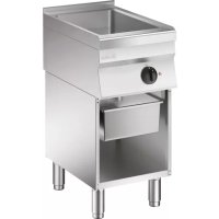
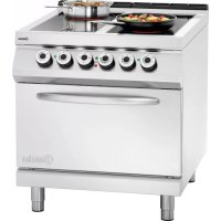
Two stainless steel kitchen appliances with control panels and side legs, one with a lid and the other with a pot (no visible text or symbols)INSTALLAT I ONS-, BEDIENUN GS-UND W ARTUNGSA NW EISU NGE N
INSTALLATION, OP ERATING AND MAINT ENANCE NSTR UCTIONS
MA NUEL D'INSTALLATION, D'UTILISATION ET D'E NTRETIEN
text_image
Technical diagram of a portable stove with labeled components and dimensions4.3. Typenschild
natural_image
Three identical cooking pots with different liquid levels and a crossed-out stand, no text or symbols present.text_image
Illustration showing three cooking pots with crossed-out black marks, likely indicating a cooking or heating step.natural_image
Simple diagram with three colored circles and a central vertical line, no text or symbols present
natural_image
Simple black horizontal line with a small circle at the top (no text or symbols)text_image
Technical diagram showing mechanical assembly with labeled components and directional arrows, including a 3D view and cross-sectional views.natural_image
Technical line drawing of a portable stove or oven with labeled component A (no text or symbols beyond label)natural_image
Technical line drawing of a mechanical assembly with labeled component M and alignment indicator (no readable text or symbols)Symbole
DE
text_image
Diagram showing a device with warning symbols and signal waves, including a lightning bolt and signal icon.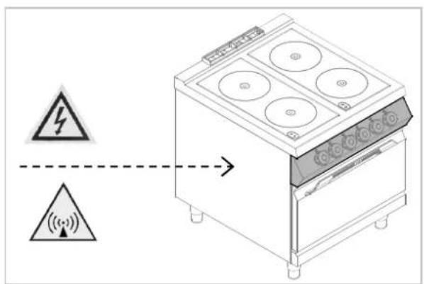
text_image
Diagram showing a device with warning symbols and signal icons, including a lightning bolt symbol and signal waves.
text_image
Diagram showing electrical hazard symbols and signal transmission from a stove to a lamp, with warning labels.4.1. General guidelines 4
4.2. Description of the appliance 4
4.3. Index plate 5
4.4. Exchange of components (service technician) 5
4.5. Protection systems 5
- USE AND OPERATION 6
5.1. Description of the use the device....6
5.2. Switching the cooking zone on/off....6
5.3. Operating manual....7
- CLEANING AND MAINTENANCE 8
6.1. Guidelines on cleaning and maintenance 8
6.2. Correct maintenance 9
6.3. Cleaning of the ceramic hob 9
- PROBLEMS DURING OPERATION 9
7.1. Detection of failures and their fixing 10
7.2. Error codes....10
7.3. Generator's error messages (E1).... 11
- INSTALLATION 12
8.1. Packaging and unpacking 12
8.2. Installation (service technician) 12
8.3. Installation of the appliance in a line 13
8.4. Connection to the mains (service technician) 13
8.5. Technical acceptance (service technician) 15
- APPLIANCE DISPOSAL 15
ATTACHMENTS....I
Bartscher GmbH
APPLIANCE DISPOSAL 15
C
Cleaning of ceramic plate 9
Connection to the mains 13
Correct maintenance 9
D
Description of the appliance 4
Description of the use the device 6
E
Error codes 10
Exchange of components 5
G
General guidelines 4
Guidelines on cleaning 8
Guidelines on regular use of the appliance 7
|
Index plate 5
Installation 12
Installation of the appliance in a line 13
L
Longer interval in the use of the appliance 7
M
Maintenance 8
0
Operation manual 7
P
Packaging 12
PROBLEMS DURING OPERATION 9
Protection systems 5
S
SAFETY 3
Switching the cooking zone on/off 6
T
Technical acceptance 15
Temperature controller 6
U
Unpacking 12
3. SAFETY

Read carefully the guidelines and
instructions in the instruction manual before you use the appliance.
The instruction manual contains general information on how to safely use and maintain the appliance. Retain the manual for future reference.

Electric installation conforms to CEI EN
60335-1 and 60335-2-36 regulation.

To prevent any hazard, the damaged
mains power cable may be replaced by the manufacturer or service personnel only.
The manufacturer took extra care when designing and manufacturing to prevent any safety or health hazard to the personnel operating the appliance.
Please read carefully the guidelines in the instruction manual and instructions placed directly onto the appliance. Above all, observe all the safety instructions.
Do not intervene in or remove the protective devices installed in the appliance. Non-compliance may lead to severe safety and health hazard against people. We recommend to perform a few tests to know the layout and main functions of the control panel, particularly those to switch the appliance on and off.
The appliance is intended only for the use it has been designed for and any other use is considered as the use not in compliance with the intended use.
The manufacturer is not liable for material damage or damage to person caused by misapplication or incorrect application of the appliance.
Any maintenance work that requires special technical license or special skills may be performed by qualified personnel only.
To provide hygiene and protect foods from dirt, all the elements that have direct or indirect contact with the foods and all border areas must be thoroughly cleaned. Use only the cleaning agents intended for use in contact with food and avoid using flammable agents or harmful to health.
After each use of the appliance make sure that all the heating elements and control elements have been switched off and the cable unplugged.
In case of prolonged interval in using the appliance disconnect all power supply cables and thoroughly clean the inside and outside elements of the appliance.

In direct connection to the mains
the safety switch should be supplied where wire joints dilation is large enough to secure disconnection in category III overvoltage, which is in accordance with the installation rules.

To prevent any risks, the damaged
supply cable must be replaced only by the manufacturer or electrician.

The device requires some safety
measures during installation, positioning, fixing, and connecting to the power supply. See chapter 8 „INSTALLATION”).

Do not clean the device with direct
stream of water.

If the surface of the glass hob is
broken, immediately disconnect the device from the power supply.

Do not place any plastic containers on
hot surfaces of the glass hob.

In order to avoid overheating, do
not place any aluminum foil or metal plates on the surface of the device.
i Scientific research has proved that the induction cooker poses no threat. Nevertheless, people with cardiac pacemaker should keep a distance of at least 60 from the working device.
Remember that wearable items, such as e.g. rings, watches etc. may get hot when they are close to the cooker's hob.
4. GENERAL INFORMATION AND WARNINGS
4.1. General guidelines
The manual has been edited by the manufacturer to provide the authorized personnel with the information necessary to work with the appliance. We recommend the intended readers to read the manual carefully and comply with the information. By reading the information contained in the manual, hazards against people health and safety may be prevented.
Retain the manual in an easily available place throughout the time of use of the appliance to have access and refer to the required information at any time.
Special symbols, described below, have been used to stress important information or draw attention to essential data:
Warning

Indicate important safety instructions. You should acquire the proper conduct to prevent hazard against people health and safety or not to cause any damage.
Caution

Indicate essentials technical data that you cannot ignore.
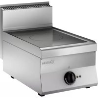
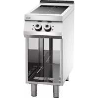
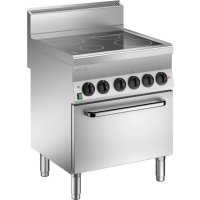
4.2. Description of the appliance
An electric cooker with an induction ceramic hob has been designed and manufactured for preparing and cooking food products in the area of commercial gastronomy.
1) Induction hob: glass ceramics
2) Cooking zone: consists of a module which transfers heat to the pot;
3) Temperature control knob: activates, deactivates and adjusts the power of the cooking zone.
4) Adjustable feet
5) Power indicator: it shows the activity of the cooking zone.
6) Alarm indicator: it shows possible malfunctions of the cooking zone.

text_image
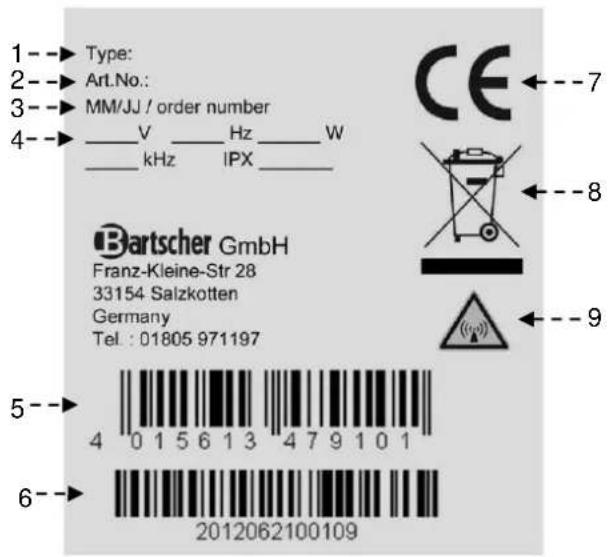
Technical diagram of a kitchen appliance with numbered components and dashed alignment lines4.3. Index plate
The index plate indicated in the drawing is mounted directly onto the device. There are all guidelines and information on the plate required for safe use.
1) Model No.
2) Code-No.:
3) Production date
4) Supply Voltage / frequency / power / magnetic field frequency / type of protection
5) EAN number
6) Serial numbers
7) CE Marking
8) WEEE symbol
9) "Electromagnetic field" symbol
text_image
1--► Type: 2--► Art.No.: 3--► MM/JJ / order number 4--► V Hz W ___ kHz IPX ____ CE ←--7 Bartscher GmbH Franz-Kleine-Str 28 33154 Salzkotten Germany Tel: 01805 971197 5-- 4 0 1 5 6 1 3 4 7 9 1 0 1 6-- 20120621001094.4. Exchange of components (service technician)

Before exchange of the component on all the existing protection es.

In particular, switch off the electric supply with the electrical potential switch. If necessary, exchange the used components to the original spare parts.
We are not liable for personal injury or damage to the components that arise due to application of other spare parts than original or intervention into the appliance without the manufacturer's consent that may have altered the safety requirements.
4.5. Protection systems
The device is equipped with the following protection systems:
- Pot detection device: It is a device which deactivates a cooking zone if there is no pot on it or if the pot is empty.
- Temperature detection device: It is a device which deactivates a cooking zone if the temperature is too high. As soon as the temperature drops below the alarm threshold, the device switches on automatically.
Check every day that the protection devices are mounted correctly and operational.
5. USE AND OPERATION
5.1. Description of the use the device
The elements controlling the essential functions are located on the control panel of the device.
A) Temperature control knob: it controls the heating power of the cooking zone
B) Green indicator light: it indicates heating of the cooking zone.
C) Red indicator light: it indicates potential malfunctioning of the cooking zone.

text_image
Front cooking zone position A Rear cooking zone position Green power indicator light B Cooking zone power Max. position C Red alarm indicator light A5.2. Switching the cooking zone on/off
In order to activate the cooking zone follow these instructions:
A) Start the automatic switch-off to turn on the electrical connection.
B) Place a pot with the food to be cooked on the selected cooking zone.
C) Turn the temperature control knob (A) clockwise, to activate the cooking zone with a minimum power, the green indicator light will come on.
D) Next, set the temperature control knob in a desired position.
E) Set the temperature control knob to 10, to switch the cooking zone to maximum power.
F) Set the temperature control knob to 0, to switch the cooking zone off. The green indicator light (V) will go off.
G) Start the automatic switch-off to turn off the electrical connection, when needed.
If a pot is removed for a short time, the generator ceases to supply power and when the pot is put in the cooking zone again, the device starts working again with the selected power.
If you simultaneously use a few pots to cook, make sure that the handles do not cross and that they are not over the cooking zone. Depending on the material, handles may become hot.

Pos. 0


Pos. 10

natural_image
Two circular mechanical components with holes, shown in a row (no text or symbols visible)5.3. Operating manual
Longer interval in the use of the appliance
When you plan not to use the appliance for the prolonged time, follow the instructions below:
- Turn on the automatic switch-off to disconnect from the mains;
- Thoroughly clean the appliance and surrounding areas;
- Apply the vaseline oil on the stainless steel surfaces;
- Perform all maintenance works.
Guidelines on regular use of the appliance
Due to the particular nature of the induction field, the cookware must have a plane magnetic bottom.
Use only cookware made of iron / enameled iron, cast iron / enameled cast iron, steel or stainless steel, if they are marked as suitable for induction cooking (acquaint yourself with the description of cookware).
Pans need to have a diameter within the range from 160 to 260 mm.

Products which are not mentioned chapter are automatically regarded luded and not suitable for use.
To ensure correct use of the device follow the guidelines below:
➢ Use only accessories provided by the manufacturer:
Use cooking zones for heating pots only, do not heat food directly on the induction hob.
The device and its vicinity should be always kept clean.
➢ Always use cookware with the diameter smaller than cooking zones.

natural_image
Three cooking pots with different sizes and a crossed-out baking pan (no text or symbols)➢ Use only pots with flat bottom.

natural_image
Three identical line drawings of cooking pots with crossed-out black marks, no text or symbols present.Frying pans for steaks made of cast iron and other metal alloys are not suitable for use on the ceramic hob, because a bottom thickness may lead to dangerous concentration of heat on the induction hob. Besides, rough bottom may scratch the surface and the metal alloy may leave permanent stains.
Use only food grade cleaning agents.
- Avoid overflowing of boiling liquids or spilling them on the hob.
Do not switch the cooking zones on without appropriate pot or pan or with empty pot or pan.
Do not place hot pans or pots on the cold cooking zones.
Keep minimum distance between the pots, make sure they do not touch each other.
Switch the cooking zone off when removing the pot from the hob to prevent reactivation of the system when it is not desired.
Do not place any materials (paper, cardboard, textiles etc.) between the pot and the cooking zone as they may catch fire.

Do not use cooking zones without Switch the cooking zones off when re not used.

Do not try to protect the induction with an aluminum foil during its ion.
i Thoroughly clean and dry pot bottoms before placing them on the cooking zone. Corrugated bottoms of pots and frying pans may leave marks and grooves when moved on the cooker.
Objects made of metal heat up fast when they are placed on the active cooking zone. Do not place any objects on the induction cooker (cans, closed boxes, aluminum, cutlery, rings, keys, watches etc.), but pots and pans.
Do not place any credit, phone cards, tapes or other magnetic objects on the surface of the glass hob of the induction cooker.
During the operation, air vents in the lower part of the device cannot be blocked or covered with pots or pans
Be careful, because sudden power supply switch-off creates a danger of burns, because cooking zones may still remain hot.
Test run
After connecting the device, perform a test run.
- Remove a pot from the cooking zone.
- Set the cooking level to "0".
- Switch the power supply on (green indicator light will flash quickly).
- Green and red indicator lights cannot remain lit or flashing.
- Set the desired cooking level.
- Green indicator light must flash evenly at 1 second intervals (pot detection mode).

- There should be no messages about device malfunctioning.
- Red indicator light should not be lit.
- Put a pot filled with water with diameter of at least 12 cm on the cooking zone.
- Green indicator light should be constantly lit.

- Set the maximum power.
- A fan must automatically start after a few minutes.
Place a pot or pan always in the middle of the hob. Do not heat empty cookware without supervision. Pans should not be heat up to more than 300 °C.
In case of any malfunctions, see chapter "Problems during operation"
6. CLEANING AND MAINTENANCE
6.1. Guidelines on cleaning and maintenance

Before you start maintenance
works, turn on all the mounted protective devices.
In particular, disconnect the electric power supply by means of the automatic switch-off.
6.2. Correct maintenance
Proper maintenance includes daily cleaning of all components which have contact with food products, and regular maintenance of drain pipes.
Careful maintenance ensures the best performance, longer life of the appliance and proper operation of the protective devices.
Never direct the water stream or high pressure jet towards the appliance.
To clean the stainless steel, do not use iron wool or iron brush as they may leave iron particles on the surface that form rust in result of oxidation.
In the case of prolonged intervals in the use of the appliance, apply the vaseline oil onto all the stainless steel surfaces.
Do not use any clearing agents that contain substances hazardous or harmful to health (solvents, petrol. etc.).
At the end of the working day clean:
▶ ceramic hob;
device.
Regularly instruct the specialist personnel to perform the following maintenance works:
▶ check the electric installation;
induction generation performance test.
6.3. Cleaning of the ceramic hob
Follow the instructions below:
➢ Switch the cooking zones off and leave to cool off;
➢ Activate the automatic switch-off to turn off the electrical connection;
Clean the cooking zone with a sponge and neutral cleaning agent.
➢ Residues and stains on the ceramic surfaces must be quickly and immediately removed when the induction hob is still hot.
➢ Wipe the induction hob and dry it afterwards.

Do not use any water jets on the induction hob, in particular when it is still hot.
Do not pour water directly onto the induction hob.
Do not use any abrasive cleaning agents!
In order to remove stubborn stains the cooker may be covered with cloth soaked in the cleaning agent for the night. Repeat cleaning the next day.
In order to remove food residues and fat splashes use a special scraper for ceramic hobs.
7. PROBLEMS DURING OPERATION
The information below is provided to recognize and repair any failures that may occur when operating the appliance.
Some of the failures can be repaired by the user, others require thorough specialist knowledge. Such problems may be solved exclusively by the qualified personnel.
7.1. Detection of failures and their fixing
| Failure Possible reason Solution | ||
| Insufficient heating of the cooking zone | Unsuitable cookware Use suitable cookware | |
| Continuous heating of cooking zone at maximum power | Defective temperature control knob | Check/replace the knob |
| Cooking zone operates without a pot | Defective pot detection | Replace the generator or have it repaired |
| Small metal objects are heated up | Defective pot detection | Replace the generator or have it repaired |
| Cooking zone does not heat up | Pot diameter smaller than 12 cm or defective pot detection | Use suitable pots |
| Damaged generator | Replace the generator or have it repaired | |
| The device does not respond | Fuses blown or power cable damaged | Check the network connection |
| The fuses glow when the appliance is switched on | Generator short-circuit | Replace the generator or have it repaired |
7.2. Error codes
Malfunction errors are detected by the generator and reported to the operator
When error occurs, a green indicator light makes one long flash followed by short flashes. Short flashes are repeated at equal intervals. A total number of short flashes corresponds to the error number.
This is a sequence of green indicator light flashes for error: E1 ↔ 06:

text_image
long long1 2 3 4 5 6 1 2 3 4 5 6Red indicator light is lit for a long time in case of error

natural_image
Simple diagram with three colored circles and a central vertical line, no text or symbols present
natural_image
Simple black horizontal line with a small circle at the top (no text or symbols)7.3. Generator's error messages (E1)
| Error code Name Possible reason Solution | |||
| E1 ↔ 01 | Overload current | Inappropriate cookware Use appropriate cookware | |
| Defective or damage inductor Check the inductor | |||
| E1 ↔ 02 | No induction current | No inductor or current at the power dividers | Connect the inductor |
| E1 ↔ 03 | IGBT temperature too high | Air vents blocked, fan contaminated, faulty IGBT temperature sensor | Clear the air ventsClean the fanContact the service company. |
| E1 ↔ 04 | Cooking zone temperature too high or too low | Empty pot | Remove the pot, switch the cooker off and wait a few minutes until the cooking zone cools down. |
| Defective temperature sensor Replace the sensor | |||
| Defective output stage Replace the generator | |||
| E1 ↔ 05 | Broken cable at the control unit | Cable has a loose contact or is broken | Switch the generator off, check the cable, replace if necessary |
| Digital service has a wrong ID. | Switch the generator off, check the DIP switch, possibly switch on. | ||
| Control unit error Check / replace a control unit | |||
| E1 ↔ 06 | Internal temperature too high or too low | Air vents blocked, contaminated fan, faulty internal temperature sensor | Clear air vents, clean the fan |
| E1 ↔ 07 | Inductor temperature | Inductor temperature too high | Remove pots, switch off and wait a few minutes until cooking zones cool down |
| Defective temperature sensor Replace sensor | |||
| E1 ↔ 08 | Mains voltage phases | No mains voltage phase or insufficient network quality | Check mains voltage phases |
| E1 ↔ 10 | Communication | LIN or CAN-bus error, no connection between the keypad and the generator | Disconnect the device from the power supply and check the connection |
| E1 ↔ 11 | Start-up | Unnecessary service field connected | Set the service field or connect to the appropriate controller |
| Digital service field has an incorrect ID | Switch the generator off and set the DIP switch correctly | ||
| Error during start-up of the equipment | Wait approx. 30 seconds for the device to update automatically | ||
| E1 ↔ 13 | Power supply connection: | Error when the supply voltage is too high or too low | Check the power supply connection |
| E1 ↔ 14 | Power adapter error | Error when the supply voltage is too high or too low | Check the power supply connection |
| E1 ↔ 15 | Empty pot protection | Power supply error | Turn off the main protection and turn it on again after a few seconds |
| Empty pot | Remove the pot, switch off and wait a few minutes until cooking zone cools down. | ||
| Defective temperature sensor Replace the temperature sensor | |||
8. INSTALLATION
8.1. Packaging and unpacking
During unloading and when installing the appliance follow the information from the manufacturer placed directly on the packaging and in this manual.
To lift and transport the product plan to use a fork lift or stacker, and pay attention to even weight distribution to avoid a risk of tilting of the packaging (avoid excessive incline!).

When using a lift truck, pay attention power cable and location of feet.
The packaging consists of the carton packaging and wooden pallet. There are symbols printed on the carton packaging that according to the international agreements inform about the regulations to follow when loading and unloading, transporting and storing the appliance.

THIS SIDE UP

CAUTION GLASS

KEEP DRY
When collecting the goods check if the packaging is complete and has not been damaged during transport.
Any damage should be immediately reported to the shipping company.
Unpack the appliance as soon as possible to check if the appliance is not damaged.
Do not use a sharp object to cut the carton box. It may damage the stainless steel inside the box.
Remove the carton packaging from bottom to top. When unpacked check if the appliance is according to the order.
In case of any difference inform the sales agent immediately.

Do not store the packaging materials (nylon bags, polystyrene foam, clips ...) in the reach of children!
Remove the protective PVC layer from the out and inner surfaces. If possible, do not use any metal tools.
8.2. Installation (service technician)
All the stages of the installation must be carefully planned.
The location should be equipped with all supply connections and production waste outlet. The location should also be properly lit and comply with all hygiene and sanitary requirements according to the binding regulations.
The appliance should be installed with the minimum 5 cm clearance from the wall.
Locate the device in the horizontal position by adjusting the individual feet.

To ensure the correct operation of appliance, the appliance must be bed and operated in the thoroughly rated room only.

Do not install in the vicinity of other device which may generate high temperatures
8.3. Installation of the appliance in a line
To fix the appliance in a line (neighboring) follow the steps:
-
Dismantle the control panel, and remove the cast iron frame from the chimney if necessary.
-
Apply the sealing tape (A) onto the joining sides.
-
Place the appliances next to each other and in a horizontal position (by adjusting the feet).
-
Connect the appliances with the joining elements.

text_image
Technical diagram showing mechanical assembly steps with labeled components and directional arrows8.4. Connection to the mains (service technician)
The device may be connected to the power supply only by the authorized and qualified personnel, when the valid regulations are followed and when appropriate material is used in accordance to the regulations.
The device is delivered adjusted to 400V 3N\~50/60 Hz working voltage.
The correct cross section of the cable is presented in the attachments and should be determined by the electrician.

To prevent any risks the damaged supply cable must be replaced only by the manufacturer or electrician.

Before connection to the power supply, make sure that the device has been initially connected with the appropriate all-pole switch with a contact opening of min. 3 mm.
To correctly connect the device, follow the guidelines below.
Remove the cover from the terminal strip (A).

natural_image
Technical line drawing of a portable stove with labeled component A (no text or symbols beyond label)Connect the switch-off to the terminal strip (B) of the device, as shown in the drawing and block diagram (see the attachment). Use the H07RN-F cable or better.
▶ Firmly press the end of the cable (C).
▶ Replace the terminal strip cover.

text_image
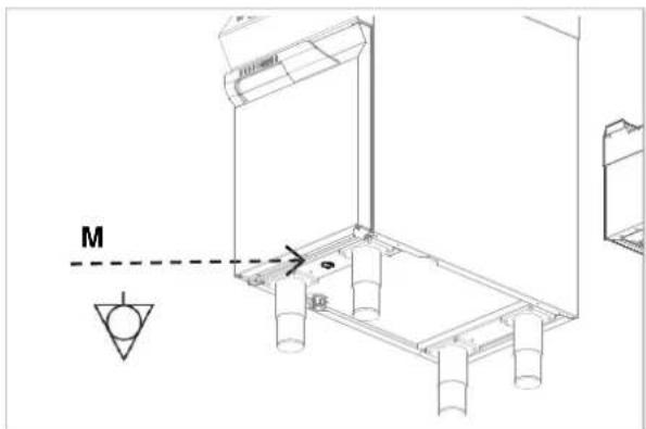
B CThe device is equipped with the equipotential clamp (M). The terminal is marked with
appropriate sticker: .
natural_image
Technical line drawing of a mechanical assembly with cylindrical components and a dashed line labeled 'M' (no text or symbols beyond basic geometry)Designation
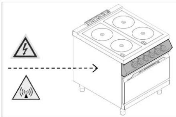
The following symbol WARNING! Electromagnetic field" informs that the electromagnetic field generated during the operation of the device may lead to hazards to the user
text_image
Diagram showing a kitchen appliance with warning symbols and signal transmission arrows, indicating electrical hazard or safety warning.
text_image
Diagram showing a device with warning symbols and signal waves, including a lightning bolt and signal icon.
text_image
Diagram showing electrical hazard symbols and signal transmission from a stove to a lamp, with warning labels in Chinese.8.5. Technical acceptance (service technician)
Before the first use, the device must be checked in order to inspect proper functioning of every component and detect possible defects
It is recommended to run the following check-ups:
- Check that the energy supply voltage is the same as of the device voltage.
- Turn on the automatic switch-off to check the electrical connections.
- Check that the protection devices work correctly.
9. APPLIANCE DISPOSAL

The appliance is marked in conformity with the European Directive 2002/96/EG WASTE ELECTRICAL AND ELECTRONIC EQUIPMENT (WEEE).

By disposing the appliance in balance with the regulations the user routes towards prevention of adverse s on environment and health.

The symbol on the product or attached manual indicates that the product cannot be considered as ordinary household waste and should be transferred to a special collection point
for electrical and electronic appliances for recycling.
Local waste management regulations should be observed.
Further information on procedure, reusing and recycling of the product is available in local offices, waste management unit or with the product sales agent.
Bartscher GmbH
- DYSFONCTIONNEMENTS....9
natural_image
Two black circular mechanical components with adjustment arrows, no visible text or symbols5.3. Mode d'emploi
natural_image
Three illustrated cooking pots with different liquid levels and a crossed-out baking pan (no text or symbols)natural_image
Three identical line drawings of a cooking pot with liquid and crossed-out black marks (no text or symbols)natural_image
Simple diagram with three colored circles and a central vertical line, no text or symbols presenttext_image
Technical diagram showing mechanical assembly steps with labeled components and directional arrowsnatural_image
Technical line drawing of a portable stove or oven with labeled component A (no text or symbols beyond label)text_image
Diagram showing a kitchen appliance with warning symbols and signal transmission arrows, indicating electrical hazard or signal flow.
text_image
Diagram showing a device with warning symbols and signal waves, including a lightning bolt and signal icon.
text_image
Diagram showing a cooking oven with warning symbols and signal transmission arrows, indicating electrical hazard or safety warning.text_image
Technical diagram of a kitchen appliance with numbered components and dashed alignment linesnatural_image
Simple line drawing of two cooking pots with steam rising, one crossed out by a diagonal line (no text or symbols)natural_image
Three identical line drawings of a pot with a lid, one marked with a crossed-out black symbol, the other with a cross symbol (no text or labels)natural_image
Simple diagram with three colored circles and a central vertical line, no text or symbols presenttext_image
Technical diagram showing mechanical assembly with labeled components and directional arrows, including a circular component and numbered parts A and g.natural_image
Technical line drawing of a mechanical device with labeled component A (no text or symbols beyond label)natural_image
Technical line drawing of a mechanical assembly with labeled component M and reference lines (no text or symbols beyond labels)Simboli
IT
Il seguente simbolo

DENZA!
text_image
Diagram showing a kitchen appliance with warning symbols and signal icons, indicating electrical hazard or safety warning.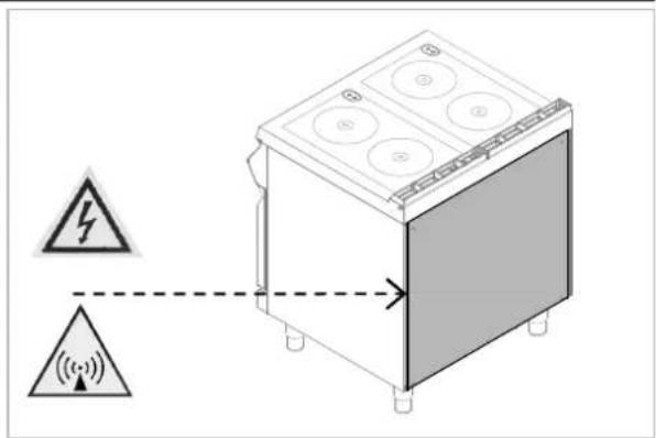
text_image
Diagram showing a device with warning symbols and signal waves, including a lightning bolt and signal wave icon.
text_image
Diagram showing electrical hazard symbols and warning signs on a stove appliance, with warning triangle and signal icon indicating electrical hazard.text_image
Illustration showing three cooking pots with different liquid levels and a crossed-out pan, likely indicating a cooking or heating scenario.text_image
Illustration showing three cooking pots with crossed-out black X marks, likely indicating a cooking or heating scenario.natural_image
Simple diagram with three colored circles and a central vertical line, no text or symbols present
natural_image
Simple black horizontal line with a small circle at the top (no text or symbols)text_image
Technical diagram showing mechanical assembly steps with labeled components and directional arrowsnatural_image
Technical line drawing of a portable stove with labeled component A (no text or symbols beyond label)text_image
Diagram showing a device with warning symbols and signal waves, indicating electrical hazard or safety warning.
text_image
Diagram showing a device with warning symbols and signal waves, including a lightning bolt and signal icon.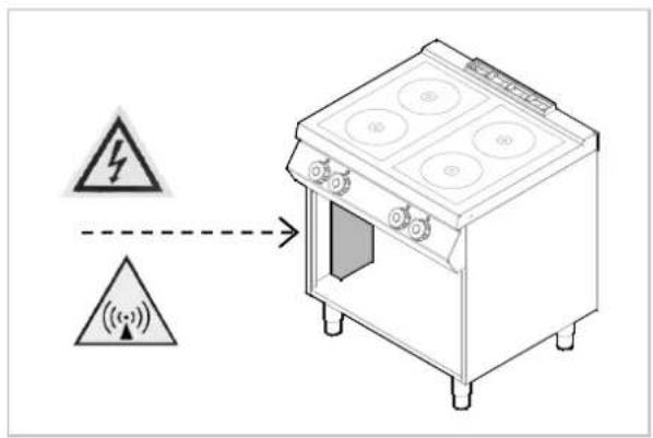
text_image
Diagram showing a kitchen appliance with warning symbols and signal icons, indicating electrical hazard or safety warning.text_image
Technical diagram of a kitchen appliance with numbered components and dashed alignment linestext_image
Illustration showing three cooking pots with different sizes and a crossed-out cooking pan, likely indicating a cooking or heating scenario.natural_image
Three identical illustrations of cooking pots with crossed-out black X marks, no text or symbols present.natural_image
Simple diagram with three colored circles and a central vertical line, no text or symbols present7.3. Comunicados sobre os erros do gerador (E1)
text_image
Technical diagram showing mechanical assembly with labeled components and directional arrows, including a circular component and force indicators.natural_image
Technical line drawing of a mechanical device with labeled component A (no text or symbols beyond label)natural_image
Technical line drawing of a mechanical assembly with labeled component M and reference lines (no text or symbols beyond labels)Símbolos
PT
text_image
Diagram showing a device with warning symbols and signal transmission arrows, indicating electrical hazard or safety warning.
text_image
Diagram showing a device with warning symbols and signal waves, including a lightning bolt and signal wave icon.
text_image
Diagram showing electrical hazard symbols and warning signs on a stove appliance, with warning triangle and signal icon indicating electrical hazard.- WERKINGSSTORING....9
7.1. Storingen herkennen en oplossen 10
7.2. Foutcodes....10
7.3. Foutberichten van de generator (E1) 11
- INSTALLATIE 12
text_image
Technical diagram of a kitchen appliance with numbered components and dashed alignment lines4.3. Typeplaat
natural_image
Two black circular mechanical components with holes, shown in a 3D rendering (no text or symbols visible)natural_image
Three identical line drawings of a cooking pot with liquid and a crossed-out pan, no text or symbols present.natural_image
Three identical line drawings of a cooking pot with liquid and a crossed-out pan, no text or symbols present.natural_image
Simple diagram with three colored circles and a central vertical line, no text or symbols present7.3. Foutberichten van de generator (E1)
text_image
Technical diagram showing mechanical assembly with labeled components and directional arrows, including a circular component and force indicators.natural_image
Technical line drawing of a portable stove or oven with labeled component A (no text or symbols beyond label)text_image
Diagram showing a cooking oven with warning symbols and signal indicators, likely illustrating safety or monitoring system.
text_image
Diagram showing a device with warning symbols and signal waves, including a lightning bolt symbol and a warning triangle.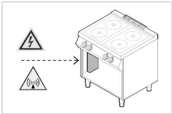
text_image
Diagram showing a cooking oven with warning symbols and signal icons, indicating electrical hazard or safety warning.8.5. Technische afname (onderhoudsmonteur)
Regulator temperature 6
Rozpakowanie 12
T
natural_image
Two black circular mechanical components with adjustment knobs, shown against a light gray background (no text or symbols)natural_image
Illustration of three cooking pots with different sizes and shapes, one marked with a crossed-out pan (no text or symbols)natural_image
Three identical illustrations of cooking pots with crossed-out black lines, no text or symbols present.natural_image
Simple diagram with three colored circles and a central vertical line, no text or symbols present
natural_image
Simple black horizontal line with a small circle at the top (no text or symbols)
CHRONIĆ PRZED
WILGOCIA
text_image
Technical diagram showing mechanical assembly with labeled components and directional arrows, including Z, i, A, and g axes.natural_image
Technical line drawing of a portable stove or oven with labeled component A (no text or symbols beyond label)text_image
Diagram showing a kitchen appliance with warning symbols and signal indicators, including a lightning bolt symbol and signal waves.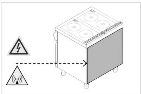
text_image
Diagram showing a device with warning symbols and signal waves, including a lightning bolt and signal icon.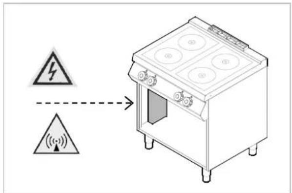
text_image
Diagram showing a house appliance with warning symbols and signal icons, indicating electrical hazard or safety warning.natural_image
Two identical gray square diagrams with black cross-like and straight lines, no text or symbols present.INDUCTION 2 x 5000 watt E.G.O.

text_image
400 303 950 905314 288 200 200 115 670 165ID092M01
ANSCHLUSSSCHEMA - CONNECTION CARD - FICHE DES RACCORDEMENTS - SCHEDA ALLACCIAMENTI - FICHA DE ENLACES - ESQUEMA DAS CONEXÕES - PLAN AANSLUITINGEN - SCHEMAT PODŁĄCZENIA

text_image
950 905 60 180 750 900 510 150 85715
text_image
800 150 100 300 100 150 75 240 510 150 20580 ONLY 220-240V 3~ 640 8080 20 800
natural_image
Two identical gray square diagrams with internal cross-like lines and dots, no text or symbols present.INDUCTION 2 x 5000 watt E.G.O.
text_image
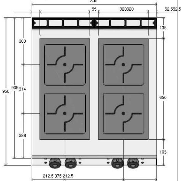
55 320320 52.552.5 135 303 905 314 950 288 650 165 212.5 375 212.5
text_image
380-415V 3~ 50/60Hz ID71 : 4G x 1.5 mmq In=12 A ID91 : 4G x 1.5 mmq In=16 A L1 L2 L3 - - + PE C COOKING ZONECOOKING ZONE ON 1234 Pin1=0 Pin2=1 ON 1234 Pin1=1 Pin2=0 = Section 0.5 mmq = Section 4 mmq = Section 6 mmq PE 3 2L1 LIN PwrMgml tt + gn + POTI Lamps CONTROL D PwrMgml tt + Sn + POTI C Lamps B PwrMgml tt + gn + POTI A GENERATOR Channel D Channel C Channel B Channel A Res. Flat Wok FlatFwdWok FlatFwdWok FlatFwdWok + Pu + ?F + ?W - + + Pu + ?F + ?W - + + Pu + ?F + ?W - + N2 Node ID Control FF 0 A FF 1 B ON 2 C ON 3 D 71 91 380-415V 3~ 50/60Hz FV122 6 POLI - 40 A - 450 V 3500 watt (2x) 5000 watt (2x) CAVO H05SJ-K Section 4 mmq COOKING ZONE B COOKING ZONE C| 1 2 3 4 | PIN1 | PIN2 | Node ID | Control |
| OFF | OFF | 0 | A | |
| ON | OFF | 1 | B | |
| OFF | ON | 2 | C | |
| ON | ON | 3 | D |
| 71 | 91 | |
| ALIMENTAZIONE FEETU | 380-415V 3~ 50/60Hz | |
| M = MORSETTIERA TERMINAL | FV122 6 POLI - 40 A - 450 V | |
| POTENZA INDUTTORE POWER | 3500 watt (2x) | 5000 watt (2x) |
| CABLAGGIO CABLE | CAVO H05SJ-K Section 4 mmq | |
text_image
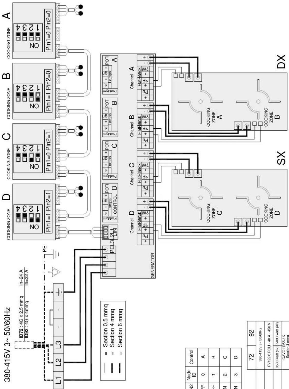
380-415V 3~ 50/60Hz ID72 : 4G x 2.5 mmq In=24 A ID92 : 4G x 4mmq In=32 A L1 L2 L3 - - PE COOKING ZONE D COOKING ZONE C COOKING ZONE B COOKING ZONE A Pin1=1 Pin2=1 Pin1=0 Pin2=1 Pin1=1 Pin2=0 Pin1=0 Pin2=0 = Section 0.5 mmq = Section 4 mmq = Section 6 mmq PEL3 LIN PwMgml nt + qnl + POTI PtWmgnl nt + qnl + POTI PtWmgnl nt + qnl + POTI PtWmgnl nt + qnl + POTI PtWmgnl nt + qnl + POTI PtWmgnl nt + qnl + POTI PtWmgnl nt + qnl + POTI PtWmgnl nt + qnl + POTI PtWmgnl nt + qnl + POTI PtWmgnl nt + qnr + POTI PtWmgnl nt + qnr + POTI PtWmgnl nt + qnr + POTI PtWmgnl nt + qnr + POTI PtWmgnl nt + qnr + POTI PtWmgnl nt + qnr + POTI PtWmgnl nt + qnr + POTI PtWmgnl nt + qnr + POTI PtWmgnl nt + qnr + POTIPtWmgnl nt + qnr + POTI PtWmgnl nt + qnr + POTI PtWmgnl nt + qnr + POTI PtWmgnl nt + qnr + POTI PtWmgnl nt + qnr + POTI PtWmgnl nt + qnr + POTI PtWmgnl nt + qnr + POTI PtWmgnl nt + qnr + POTI PtWmgn l n GENERATOR Channel D Channel C Channel B Channel A + Pu FlatFswok - + + Pu FlatFswok - + + Pu FlatFswok - + + Pu FlatFswok - + SN SX DX N2 Node ID Control FF 0 A FF 1 B ON 2 C ON 3 D 72 92 380-415V 3~ 50/60Hz FV122 6 POLI - 40 A - 450 V 3500 watt (4x) 5000 watt (4x) CAVO H0SSJ K Section 4 mmq| 1 2 3 4 | PIN1 | PIN2 | Node ID | Control |
| OFF | OFF | 0 | A | |
| ON | OFF | 1 | B | |
| OFF | ON | 2 | C | |
| ON | ON | 3 | D |
| 72 | 92 | |
| ALIMENTAZIONE FEED | 380-415V 3-50/60Hz | |
| M = MORSETTIERA TERMINAL | FV122 6 POLI - 40 A - 450 V | |
| POTENZA INDUTTORE POWER | 3500 watt (4x) | 5000 watt (4x) |
| CABLAGGIO CABLE | CAVO H05SJ-K Section 4 mmq | |
NOTE
NOTE
DE
IN COMPLIANCE WITH THE LAW IN FORCE, IT IS PROHIBITED TO REPRODUCE AND/OR DISTRIBUTE THIS MANUAL IN ANY WAY WITHOUT THE AUTHORISATION OF THE PROPRIETOR!
FR
AUX TERMES DE LA LOI, LA PROPRIETE DE CETTE NOTICE EST RESERVEE. IL EST DONC INTERDIT DE LA REPRODUIRE ET/OU DE LA DISTRIBUER SOUS QUELQUE FORME QUE CE SOIT SANS NOTRE AUTORISATION!