
115090 - Electric oven BARTSCHER - Free user manual and instructions
Find the device manual for free 115090 BARTSCHER in PDF.
| Product Type | Professional gas lava stone grill |
| Brand | Bartscher |
| Model | 115090 |
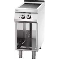
| Usage | Professional, direct cooking of food (meats, fish, vegetables) |
| Power Supply | Gas and electric (piezoelectric igniter) |
| Gas Type | Adaptable (interchangeable injectors) |
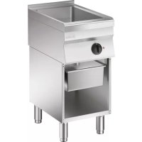
| Material | Polished stainless steel |
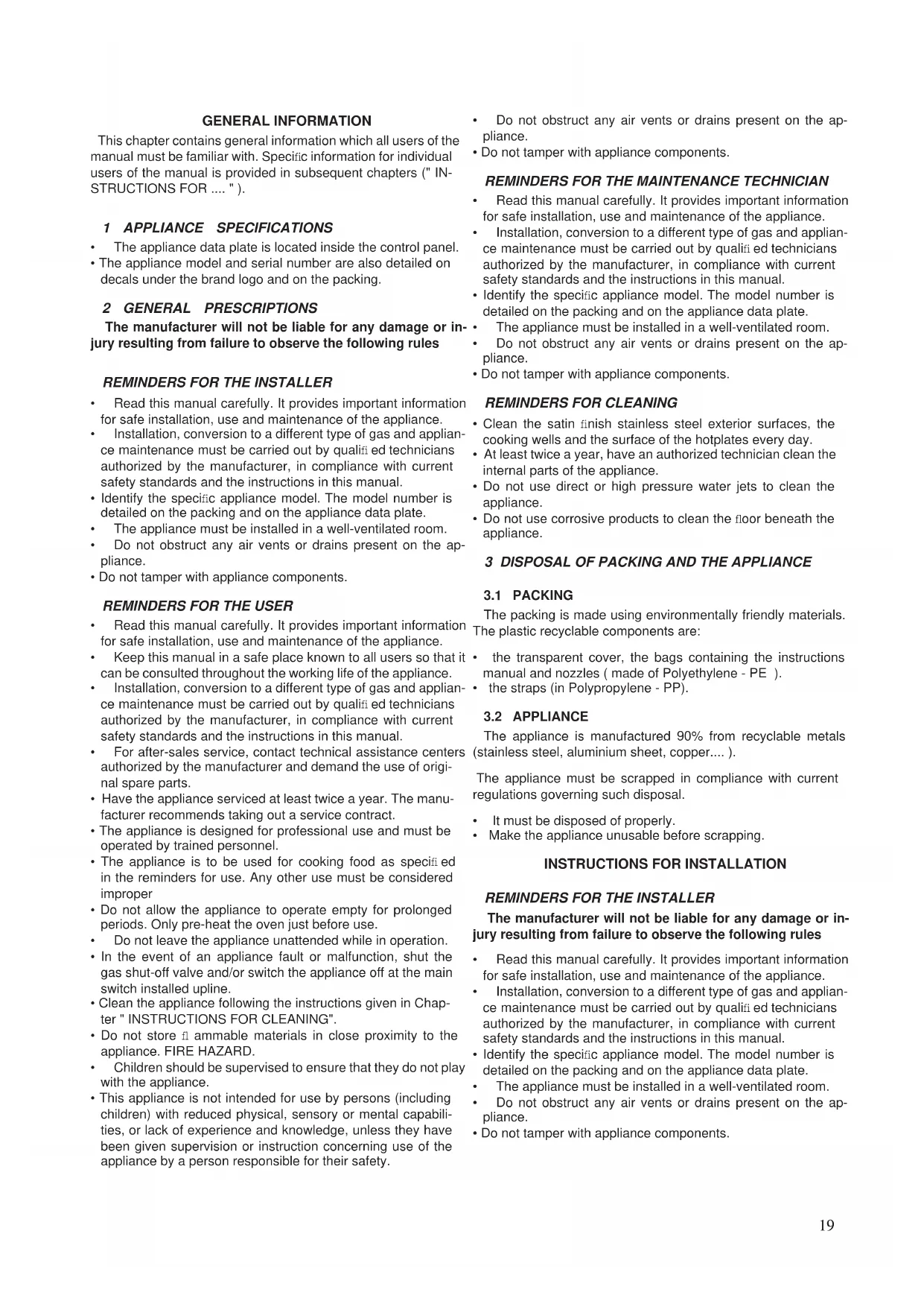
| Cooking Surface | Cast iron or steel grates, tilting/horizontal fish grill |
| Lava Stone | Volcanic, diameter 25-30 mm, max length 50 mm, 6 kg per burner |
| Grease Collection | Removable collection drawer |
| Ignition | Pilot light with piezoelectric igniter, min/max flame adjustment |
| Safety | Thermocouple, pilot light, safety shut-off |
| Installation | On base, not built-in, min distance 10 cm from walls |
| Electrical Connection | Omnipolar circuit breaker, H05 RN-F cord, grounding |
| Gas Connection | According to standards, flue type A1, B21 or B11 |
| Daily Maintenance | Clean stainless steel surfaces with non-abrasive products |
| Periodic Maintenance | Internal cleaning by approved technician at least 2 times per year |
| Spare Parts | Injector, main burner, pilot light, thermocouple, spark plug, gas valve |
| Repairability | Intervention by qualified installer, original parts recommended |
| Standards | Compliant with EN1717, current water and safety regulations |
Frequently Asked Questions - 115090 BARTSCHER
User questions about 115090 BARTSCHER
0 question about this device. Answer the ones you know or ask your own.
Ask a new question about this device
Download the instructions for your Electric oven in PDF format for free! Find your manual 115090 - BARTSCHER and take your electronic device back in hand. On this page are published all the documents necessary for the use of your device. 115090 by BARTSCHER.
USER MANUAL 115090 BARTSCHER
Read the general informations immediately!
G Attacco arrivo gas - Gasanschluss - Gas connection
Arriveè gaz - Union da gas - Gasaansluiting -
EN 10226-1 R 1/2; EN ISO 228-1 G 1/2 (DK)
DATI TECNICI - TECHNICAL DATA - TECHNISCHE DATEN - CARACTERISTIQUES TECHNIQUES - DATOS TECNICOS - TECHNISCHE GEGEVENS
| T1 | ||||||||
| Ugelli e regolazioni - Düsen und Einstellungen - Nozzles and settingsBuses et les paramètres - Boquillas y los ajustes - Nozzles en instellingen | ||||||||
| Paese - LandCountry - Pays - País | Gas - Gaz | Pa (mbar) | GPL64G | EGL62T | OGPL64G | 6NGL/G400 | ||
| GPL68G | EGL64T | OGPL68G | 6NGL/G800 | |||||
| AT - BE - BG - CH - CZ - DEDK - EE - ES - FI - FR - GBGR - HR - IE - IT - LT - LULV - NO - PL - PT - RO - SESI - SK - TR | G20G20/G25 | 2020/25 | UM | 205 205 205 | 205 | 205 | ||
| P | 27 27 27 27 | |||||||
| A (mm) | 0 | 0 | 0 | |||||
| Um | 140 140 140 | 140 | ||||||
| DE | G25 | 20 | UM | 220 220 220 | 220 | 220 | ||
| P | 27 27 27 27 | |||||||
| A (mm) | 0 | 0 | 0 | |||||
| Um | 140 140 140 | 140 | ||||||
| NL G25 | 25 | UM | 205 205 205 | 205 | 205 | |||
| P | 27 27 27 27 | |||||||
| A (mm) | 0 | 0 | 0 | |||||
| Um | 140 140 140 | 140 | ||||||
| HU | G20 | 25 | UM | 190 190 190 | 190 | 190 | ||
| P | 27 27 27 27 | |||||||
| A (mm) | 0 | 0 | 0 | |||||
| Um | 140 140 140 | 140 | ||||||
| HU | G25.1 | 25 | UM | 220 220 220 | 220 | 220 | ||
| P | 27 27 27 27 | |||||||
| A (mm) | 0 | 0 | 0 | |||||
| Um | 140 140 140 | 140 | ||||||
| BE - BG - CY - CZ - DK - EEES - FI - FR - GB - GR - HRHU - IE - IT - LT - LU - LVMT - NL - NO - PT - RO - SESI - SK - TR | G30/G31 | 28-30/3728-30 | UM | 130 130 130 | 130 | 130 | ||
| P | 14 14 14 14 | |||||||
| A (mm) | 0 | 0 | 0 | |||||
| Um | 90 90 90 90 | |||||||
| PL | G30/G31 | 37 | UM | 125 125 125 | 125 | 125 | ||
| P | 14 14 14 14 | |||||||
| A (mm) | 0 | 0 | 0 | |||||
| Um | 90 90 90 90 | |||||||
| AT - CH - DE - HU | G30/G31 | 50 | UM | 115 115 115 | 115 | 115 | ||
| P | 14 14 14 14 | |||||||
| A (mm) | 0 | 0 | 0 | |||||
| Um | 90 90 90 90 | |||||||
| IT - CH - SE - DK | G110 | 8 | UM | 480 480 480 | 480 | 480 | ||
| P | 50 50 50 50 | |||||||
| A (mm) | 0 | 0 | 0 | |||||
| Um | reg reg reg reg | |||||||
| SE | G120 | 8 | UM | 420 420 420 | 420 | |||
| P | 50 50 50 50 | |||||||
| A (mm) | 0 | 0 | 0 | |||||
| Um | reg reg reg reg | |||||||
| Um : Ugello MAX - Düse MAX - MAX nozzle - Buse MAX - Boquilla MÁX. - Sproeier MAX | ||||||||
| Um : Ugello MIN - Düse MIN - MIN nozzle - Buse MIN - Boquilla MIN - Sproeier MIN | ||||||||
| P : Pilota - Zündbrenner - Pilot - Veilleuse gaz - Piloto - Waakvlam | ||||||||
| A : Apertura Aereatore - Öffnen Luftring - Aerator Opening - Ouverture Aérateur - Abertura del aireador - Opening beluchter | ||||||||
| Pa : Pressione di allacciamento - Anschlussdruck - Supply pressurePression de raccordement - Pressión de conexión - Aansluitdruck | ||||||||
| reg : Regolato - Eingestellt - Regulated - Régie - Regulado - Geregeld | ||||||||
DATI TECNICI - TECHNICAL DATA - TECHNISCHE DATEN - CARACTERISTIQUES TECHNIQUES - DATOS TECNICOS - TECHNISCHE GEGEVENS
| T2 | |||||
| Categorie a pressioni - Kategorien e Druck - Categories and pressures - Catégories et pressions - Las categorías y las presiones - Categorieën en druk | |||||
| Paese - Land - Country - Pays - Pais | CategoriaKategorieCategoryCatégorieCategoríaCategorie | GasGaz | Pressione di allacciamentoAnschlussdruckSupply pressurePression de raccordementPressión de conexiónAansluitdruck(mbar) | ||
| Nom.Neen.Norm.Normal | Min. Max. | ||||
| LU; PL I2E G20 20 17 25 | |||||
| NO I2H G20 20 17 25 | |||||
| NL I2L G25 25 20 30 | |||||
| LU I3+ G30/G31 28-30/37 20/25 35/45 | |||||
| NO; NL; CY; MT I3B/P G30/G31 28-30 25 35 | |||||
| PL | I3B/P G30/G31 37 | 25 | 45 | ||
| BE; FR | II2E+3+ | G20/G25 | 20/25 | 17 | 25/30 |
| G30/G31 28-30/37 20/25 | 35/45 | ||||
| DE | II2ELL3B/P | G20 | 20 | 17 25 | |
| G25 | 20 | 18 25 | |||
| G30/G31 | 50 | 42,5 | 57,5 | ||
| ES; GB; GR; IE; IT; PT; SK | II2H3+ | G20 | 20 | 17 25 | |
| G30/G31 28-30/37 20/25 | 35/45 | ||||
| FI; BG; EE; LV; LT; CZ; SI; TR; HR; RO | II2H3B/P | G20 | 20 | 17 25 | |
| G30/G31 | 28-30 | 25 35 | |||
| AT; CH | II2H3B/P | G20 | 20 | 17 25 | |
| G30/G31 | 50 | 42,5 | 57,5 | ||
| HU | II2HS3B/P | G20 | 25 | 18 33 | |
| G25.1 | 25 | 18 33 | |||
| G30/G31 | 28-30 | 25 35 | |||
| HU | II2HS3B/P | G20 | 25 | 18 33 | |
| G25.1 | 25 | 18 33 | |||
| G30/G31 | 50 | 42,5 | 57,5 | ||
| SE | III1ab2H3B/P | G20 | 20 | 17 | 25 |
| G30/G31 | 28-30 | 25 35 | |||
| G110 | 8 | 6 | 15 | ||
| G120 | 8 | 6 | 15 | ||
| DK | III1a2H3B/P | G20 | 20 | 17 | 25 |
| G30/G31 | 28-30 | 25 35 | |||
| G110 | 8 | 6 | 15 | ||
| IT; CH | II1a2H | G20 | 20 | 17 | 25 |
| G110 | 8 | 6 | 15 | ||
T3
| Dati tecnici apparecchiature gas - Technische Daten gasgeräte - Technical data of gas appliancesCaractéristiques techniques des appareils à gaz - Datos técnicos de los equipos de gas - Technische gegevens gasapparaten | ||||||||||||||||
| Modelli Modelle Models Modèles Modelos Modellen A | Modelli Modelle Models Modèles Modelos Modellen B | Modelli Modelle Models Modèles Modelos Modellen C | Modelli Modelle Models Modèles Modelos Modellen D | Larghezza Breite Width Largeur Anchura Breedte | 5 W | Consumo gas complessivo - Gasamtgasverbrauch - Totala gas consumptionConsommation totale de gaz - Consumo total de gas - Totaal gasverbruik | ||||||||||
| G20 (20) | G25 (25) | G25 (20) | G20 (25) | G25.1 (25) | G110 (8) | G120 (8) | G30 (29) | G30 (37) | G30 (50) | |||||||
| mm kW | m3/h | m3/h | m3/h m3/h | m3/h m3/h | m3/h m3/h | kg/h kg/h | kg/h kg/h | |||||||||
| GPL64G | EGL62T | OGPL64G 6 | NGL/G400 4 | 00 7 0,74 | 0,86 | 0,86 | 0,74 | 0,86 1,81 | 1,61 | 0,55 | 0 | 5 | 5 0 | , | 5 5 | |
| GPL68G | EGL64T | OGPL68G | 6NGL/G800 | 800 | 14 | 1,48 | 1,72 | 1,72 | 1,48 | 1,72 | 3,61 | 3,21 | 1,10 | 1,10 | 1,10 | |
FIGURE - ABB. - FIG.


REMINDERS FOR CLEANING 19
3 DISPOSAL OF PACKING AND THE APPLIANCE....19
INSTRUCTIONS FOR INSTALLATION....19
REMINDERS FOR THE INSTALLER....19
4 REFERENCE STANDARDS AND LAWS....20
5 UNPACKING 20
6 POSITIONING....20
7 FUMES EXHAUST SYSTEM....20
8 CONNECTIONS....20
INSTRUCTIONS FOR USE....21
REMINDERS FOR THE USER 21
11 POSITIONING THE GRILLES 21
12 USING THE GAS LAVA STONE GRILL....21
13 PROLONGED DISUSE 21
INSTRUCTIONS FOR CLEANING....22
REMINDERS FOR CLEANING 22
14 GAS LAVA STONE GRILL 22
INSTRUCTIONS FOR MAINTENANCE 22
REMINDERS FOR THE MAINTENANCE TECHNICIAN 22
15 CONVERSION TO A DIFFERENT TYPE OF GAS 22
16 COMMISSIONING 22
17 TROUBLESHOOTING 22
18 REPLACING COMPONENTS....22
REMINDERS FOR REPLACING COMPONENTS....22
This chapter contains general information which all users of the manual must be familiar with. Specific information for individual users of the manual is provided in subsequent chapters ("INSTRUCTIONS FOR ....").
1 APPLIANCE SPECIFICATIONS
• The appliance data plate is located inside the control panel.
- The appliance model and serial number are also detailed on decals under the brand logo and on the packing.
2 GENERAL PRESCRIPTIONS
The manufacturer will not be liable for any damage or injury resulting from failure to observe the following rules
REMINDERS FOR THE INSTALLER
- Read this manual carefully. It provides important information for safe installation, use and maintenance of the appliance.
- Installation, conversion to a different type of gas and appliance maintenance must be carried out by qualified technicians authorized by the manufacturer, in compliance with current safety standards and the instructions in this manual.
- Identify the specific appliance model. The model number is detailed on the packing and on the appliance data plate.
• The appliance must be installed in a well-ventilated room. - Do not obstruct any air vents or drains present on the appliance.
- Do not tamper with appliance components.
REMINDERS FOR THE USER
- Read this manual carefully. It provides important information for safe installation, use and maintenance of the appliance.
- Keep this manual in a safe place known to all users so that it can be consulted throughout the working life of the appliance.
- Installation, conversion to a different type of gas and appliance maintenance must be carried out by qualified technicians authorized by the manufacturer, in compliance with current safety standards and the instructions in this manual.
- For after-sales service, contact technical assistance centers authorized by the manufacturer and demand the use of original spare parts.
- Have the appliance serviced at least twice a year. The manufacturer recommends taking out a service contract.
- The appliance is designed for professional use and must be operated by trained personnel.
- The appliance is to be used for cooking food as specified in the reminders for use. Any other use must be considered improper
- Do not allow the appliance to operate empty for prolonged periods. Only pre-heat the oven just before use.
- Do not leave the appliance unattended while in operation.
- In the event of an appliance fault or malfunction, shut the gas shut-off valve and/or switch the appliance off at the main switch installed upline.
- Clean the appliance following the instructions given in Chapter "INSTRUCTIONS FOR CLEANING".
- Do not store fl ammable materials in close proximity to the appliance. FIRE HAZARD.
• Children should be supervised to ensure that they do not play with the appliance. -
This appliance is not intended for use by persons (including children) with reduced physical, sensory or mental capabilities, or lack of experience and knowledge, unless they have been given supervision or instruction concerning use of the appliance by a person responsible for their safety.
-
Do not obstruct any air vents or drains present on the appliance.
- Do not tamper with appliance components.
REMINDERS FOR THE MAINTENANCE TECHNICIAN
- Read this manual carefully. It provides important information for safe installation, use and maintenance of the appliance.
- Installation, conversion to a different type of gas and appliance maintenance must be carried out by qualified technicians authorized by the manufacturer, in compliance with current safety standards and the instructions in this manual.
- Identify the specific appliance model. The model number is detailed on the packing and on the appliance data plate.
• The appliance must be installed in a well-ventilated room. - Do not obstruct any air vents or drains present on the appliance.
- Do not tamper with appliance components.
REMINDERS FOR CLEANING
- Clean the satin finish stainless steel exterior surfaces, the cooking wells and the surface of the hotplates every day.
- At least twice a year, have an authorized technician clean the internal parts of the appliance.
- Do not use direct or high pressure water jets to clean the appliance.
- Do not use corrosive products to clean the floor beneath the appliance.
3 DISPOSAL OF PACKING AND THE APPLIANCE
3.1 PACKING
The packing is made using environmentally friendly materials. The plastic recyclable components are:
- the transparent cover, the bags containing the instructions manual and nozzles (made of Polyethylene - PE).
• the straps (in Polypropylene - PP).
3.2 APPLIANCE
The appliance is manufactured 90% from recyclable metals (stainless steel, aluminium sheet, copper....).
The appliance must be scrapped in compliance with current regulations governing such disposal.
• It must be disposed of properly.
• Make the appliance unusable before scrapping.
INSTRUCTIONS FOR INSTALLATION
REMINDERS FOR THE INSTALLER
The manufacturer will not be liable for any damage or injury resulting from failure to observe the following rules
- Read this manual carefully. It provides important information for safe installation, use and maintenance of the appliance.
- Installation, conversion to a different type of gas and appliance maintenance must be carried out by qualified technicians authorized by the manufacturer, in compliance with current safety standards and the instructions in this manual.
- Identify the specific appliance model. The model number is detailed on the packing and on the appliance data plate.
• The appliance must be installed in a well-ventilated room. - Do not obstruct any air vents or drains present on the appliance.
- Do not tamper with appliance components.
4 REFERENCE STANDARDS AND LAWS
Install the appliance in compliance with current safety standards.
Install the appliance in compliance with the prescriptions of EN1717 and the water pollution regulations in force in your country.
5 UNPACKING
Check the state of the packing and in the event of damage, ask the delivery person to inspect the goods.
- Remove the packing
- Remove the protective film from the external panels. Use a suitable solvent to remove any residual adhesive from the panels
6 POSITIONING
- The overall dimensions of the appliance and the position of connections are given on the installation diagram at the start of this manual.
- The appliance can be installed singly or in combination with other appliances in the same product range.
- The appliance is not suitable for integrated installation.
- Position the appliance at least 10 cm from adjacent walls. This distance can be reduced in the presence of non-combustible walls or heat-insulated walls.
6.1 APPLIANCE ASSEMBLY WITH BASE
Follow the instructions provided with the type of support utilized.
6.2 JOINING APPLIANCES TOGETHER IN LINE
- Place the appliances side by side and adjust the tops to the same height.
- Unite the appliances using the special unionjoint-coverings supplied upon request
7 FUMES EXHAUST SYSTEM
Create a fumes exhaust system based on the "Type" of appliance. The "Type" is stated on the appliance data plate.
7.1 APPLIANCE TYPE "A1"
- Position the "A1" type appliance below an extractor hood to ensure smoke and fumes generated by cooking are removed
7.2 APPLIANCE TYPE "B21"
- Position the "B21" type appliance below an extractor hood
7.3 APPLIANCE TYPE "B11"
- Fit the "B11" type appliance with a suitable flue, available from the appliance manufacturer Follow the assembly instructions provided with the flue.
- Connect the flue to a 150/155 mm diameter hose, heat resistant to 300°C.
- Vent to the outside or into an efficient flue. The hose length must not exceed 3 metres.
8 CONNECTIONS
The position and dimensions of connections are given in the installation diagram at the start of this manual.
8.1 ELECTRICAL CONNECTIONS
Check that the appliance is designed to operate at the voltage and frequency of the power supply present on site. Check the details given on the appliance data plate.
- At an easily accessible point upline of the appliance, fit an all-pole disconnect switch of suitable capacity with a contact breaking distance of at least 3 mm, and a highly sensitive differential protection device. The maximum permitted leakage current is 1 mA/kW.
- A flexible rubber cable with insulation specifications not lower than type H05 RN-F must be used for connection.
- Connect the power supply cable to the terminal board as shown in the wiring diagram supplied with the appliance.
- Secure the power supply cable with the cable clamp.
- Protect the power supply cable on the outside of the appliance with a rigid plastic or metal pipe.
8.2 PROTECTIVE EARTH AND EARTH BONDING CONNECTIONS
Connect the appliance to an efficient ground circuit. Connect the earth conductor to the terminal with the symbol 1/2 located next to the main terminal board.
Connect the metal structure of the appliance to the equipotential node. Connect the conductor to the terminal with the
symbol ▽ on the outside part of the bottom.
8.3 CONNECTION TO THE WATER SUPPLY
The appliance must be connected to a potable water supply. The water inlet pressure must be between 150 kPa and 300 kPa. Use a pressure reducer if the inlet pressure is above the maximum permitted level.
- Install a mechanical filter and a shut-off valve upstream of the appliance in an easily accessible point.
- Make sure the water circuit is free from ferrous particles before connecting the filter and the appliance.
- Seal any unused connectors with a plug.
- Once the appliance has been installed, check for gas leaks at the connection points.
8.4 CONNECTION TO THE WATER DRAIN
The water drainage system must be provided using materials resistant to temperatures of 100\ °C . The bottom of the appliance must not be subjected to steam produced by drainage of hot water.
9.1 REPLACING THE MAIN BURNER NOZZLE AND ADJUSTING THE PRIMARY AIR FLOW
- Remove the control panel.
- Unscrew nozzle UM and change it with the proper one according to Table T1.
- Loose fixing screw V and operating on the shutter adjust primary air inlet at the distance "A" indicated on Table T1.
- Screw down fixing screw V and seal it with red paint.
9.2 REPLACING THE MINIMUM ADJUSTMENT SCREW
- Remove the control panel.
- Unscrew the minimum adjustment screw Um and replace it with the proper one indicated Table T1.
- Re-assemble all parts. For assembly, proceed in reverse order.
9.3 REPLACING THE PILOT BURNER NOZZLE
- Remove the control panel.
- Undo connector R.
- Remove nozzle UP and replace it with the one indicated in table T1.
- Retighten the connector R. Re-assemble all parts.
- For assembly, proceed in reverse order.
10 COMMISSIONING
See Chapter "INSTRUCTIONS FOR MAINTENANCE"
INSTRUCTIONS FOR USE
REMINDERS FOR THE USER
The manufacturer will not be liable for any damage or injury resulting from failure to observe the following rules
- Read this manual carefully. It provides important information for safe installation, use and maintenance of the appliance.
- Keep this manual in a safe place known to all users so that it can be consulted throughout the working life of the appliance.
- Installation, conversion to a different type of gas and appliance maintenance must be carried out by qualified technicians authorized by the manufacturer, in compliance with current safety standards and the instructions in this manual.
- For after-sales service, contact technical assistance centers authorized by the manufacturer and demand the use of original spare parts.
- Have the appliance serviced at least twice a year. The manufacturer recommends taking out a service contract.
- The appliance is designed for professional use and must be operated by trained personnel.
- The appliance is to be used for cooking food as specified in the reminders for use. Any other use must be considered improper
- Do not allow the appliance to operate empty for prolonged periods. Only pre-heat the oven just before use.
- Do not leave the appliance unattended while in operation.
- In the event of an appliance fault or malfunction, shut the gas shut-off valve and/or switch the appliance off at the main switch installed upline.
- Clean the appliance following the instructions given in Chapter "INSTRUCTIONS FOR CLEANING".
- Do not store fl ammable materials in close proximity to the appliance. FIRE HAZARD.
- Do not obstruct any air vents or drains present on the appliance.
- Do not tamper with appliance components.
• Children should be supervised to ensure that they do not play with the appliance. - This appliance is not intended for use by persons (including children) with reduced physical, sensory or mental capabilities, or lack of experience and knowledge, unless they have been given supervision or instruction concerning use of the appliance by a person responsible for their safety.
Important: To avoid flames, always remove any deposits of food, dirt or oil left over from the previous cooking cycles before switching on the appliance.
11 POSITIONING THE GRILLES
FISH GRID
- The cooking grille can be used in two positions: sloping or horizonta.
CAST IRON GRILLES FOR MEAT
- The cooking grille can be used in two positions: sloping or horizonta.
STAINLESS STEEL GRILLES FOR MEAT
• The cooking grille can be used in positions sloping.
12 USING THE GAS LAVA STONE GRILL
REMINDERS FOR USE
- The appliance is designed for cooking foods directly on the grille (steaks, hamburgers, fish, vegetables, etc.).
- The grill must not be used to heat pans or saucepans.
Loading the lava stone
- The appliances come complete with 1 packs of lava stone for each brazier (cooking zone).
• Each pack weighs 6 kg. - The lava stones have a min. diameter of 25mm, a max. diameter of 30mm and a max. length of 50mm, with a +/- 5% tolerance.
- Distribute the contents of one pack evenly between the braziers. Do not under any circumstances use more lava stone than recommended.
Grease collection tray
Any grease from cooking which drips into the grill and passes through the brazier is collected in the grease collection tray. Periodically empty and clean this tray.
BURNER IGNITION AND EXTINCTION
The gas tap control knob has the following positions:

★Pilot ignition
Minimum flame
Maximum flame
Pilot ignition
Press and turn the knob to position*. Press the knob down fully and light the pilot using the piezoelectric igniter.
- Hold the knob down for about 20 seconds before releasing it. If the pilot fl ame goes out, repeat the operation.
Main burner ignition
Turn the knob from position★ " to "
Next, depending on cooking requirements, turn the knob to any position between "▲" and "▲".
Switching off
To switch the main burner off, turn the knob to position★".
To switch off the pilot flame, press and turn the knob to position

13 PROLONGED DISUSE
Before any prolonged disuse of the appliance, proceed as follows:
• Clean the appliance thoroughly.
- Rub stainless steel surfaces with a cloth soaked in Vaseline oil to create a protective film.
- Leave lids open.
- Shut off taps and main switches upline of appliances.
Following prolonged disuse, proceed as follows: - Inspect the appliance thoroughly before using it again.
- Allow electric appliances to operate at the lowest temperature for at least 60 minutes.
INSTRUCTIONS FOR CLEANING
REMINDERS FOR CLEANING
The manufacturer will not be liable for any damage or injury resulting from failure to observe the following rules
- Disconnect the appliance electric supply, if present, before carrying out any operation.
- Clean the satin finish stainless steel exterior surfaces, the cooking wells and the surface of the hotplates every day.
- At least twice a year, have an authorized technician clean the internal parts of the appliance.
- Do not use direct or high pressure water jets to clean the appliance.
- Do not use corrosive products to clean the floor beneath the appliance.
SATIN FINISH STAINLESS STEEL SURFACES
- Clean the surfaces with a cloth or sponge using water and proprietary non-abrasive detergents. Follow the direction of the satin fi nish lines. Rinse repeatedly and dry thoroughly.
- Do not use pan scourers or other iron items.
- Do not use chemical products containing chlorine.
- Do not use sharp objects which might scratch and damage the surfaces.
COLLECTION TRAYS
Clean the surface, removing grease, oil, food residue etc...
- Lift up and remove the cooking grille and the brazier containing the lava stone.
- Proceed to clean the burner around the flame zone and along the flame protector apertures using a wire brush to eliminate all traces of dust, burnt-on residue and refractory material used in the brazier, whilst taking care not to enlarge the flame apertures.
INSTRUCTIONS FOR MAINTENANCE
REMINDERS FOR THE MAINTENANCE TECHNICIAN
The manufacturer will not be liable for any damage or injury resulting from failure to observe the following rules
- Read this manual carefully. It provides important information for safe installation, use and maintenance of the appliance.
- Installation, conversion to a different type of gas and appliance maintenance must be carried out by qualified technicians authorized by the manufacturer, in compliance with current safety standards and the instructions in this manual.
- Identify the specific appliance model. The model number is detailed on the packing and on the appliance data plate.
• The appliance must be installed in a well-ventilated room. - Do not obstruct any air vents or drains present on the appliance.
- Do not tamper with appliance components.
15 CONVERSION TO A DIFFERENT TYPE OF GAS
See Chapter " Instructions for installation "
16 COMMISSIONING
Following installation, conversion to a different type of gas or any maintenance operations, check appliance operation. In the event of any malfunction, consult the next Paragraph "Troubleshooting".
16.1 GAS APPLIANCES
Switch on the appliance as directed in the instructions and reminders for use given in Chapter "INSTRUCTIONS FOR USE" and check:
• the gas supply pressure (see next Paragraph).
- the correct ignition of the burners and the effectiveness of the fumes removal system.
16.1.1 CHECKING THE GAS SUPPLY PRESSURE
- To measure the gas supply pressure use a manometer with a minimum definition of 0.1 mbar.
- Remove the control panel.
- Remove the screw from the pressure test point PP and connect the manometer to the test point.
- Make the measurement with the appliance in operation.
IMPORTANT! If the gas supply pressure is not within the limits (Min. - Max) indicated in Table T2, cease operation of the appliance and contact the gas utility company. - Disconnect the manometer and retighten the retaining screw on the pressure connection.
17 TROUBLESHOOTING
The pilot burner does not light
Possible causes:
• Insufficient gas supply pressure.
- Blocked tubing or nozzle.
• Defective gas tap or valve.
- Igniter defective or not properly connected.
- Igniter or igniter wire defective.
Pilot burner goes out during use
Possible causes:
• Insuffi cient gas supply pressure.
• Defective gas tap or valve.
- Defective thermocouple or insufficient heating.
• Thermocouple incorrectly connected to gas tap or valve.
- Knob of gas tap or valve not pressed sufficiently.
The main burner does not light ( even though pilot is lit )
Possible causes:
• Defective burner ( gas outlet holes clogged ).
18 REPLACING COMPONENTS
REMINDERS FOR REPLACING COMPONENTS.
- Disconnect the appliance electric supply, if present, before carrying out any operation.
• After replacing a gas system component, check for gas leaks at connection points.
- After replacing an electrical system component, check it is correctly wired.
Replacing the gas tap
- Remove the control panel.
- Remove and replace the component.
- Re-assemble all parts. For assembly, proceed in reverse order.
Replacing the pilot burner and thermocouple.
- Remove the control panel.
- Remove the grilles, lava stone and support brazier.
- Remove and replace the component.
- Re-assemble all parts. For assembly, proceed in reverse order.
Replacing the main burner.
- Remove the grilles, lava stone and support brazier.
- Remove and replace the component.
- Re-assemble all parts. For assembly, proceed in reverse order.
19 CLEANING THE INTERIOR
• Check the condition of the inside of the appliance.
- Remove any built-up dirt.
- Check and clean the fumes exhaust system.
20 MAIN COMPONENTS
- Main burner
- Pilot burner
- Thermocouple
- Igniter
- Piezoelectric ignition
Gas tap - Brazier
- Volcanic lava stone
INFORMATIONS GÉNÉRALES 25
1 DONNÉES DE L'APPAREIL 25
2 AVERTISSEMENTS GÉNÉRAUX 25
AVERTISSEMENTS POUR L'INSTALLATEUR....25
AVERTISSEMENTS POUR L'UTILISATEUR....25
8 RACCORDEMENTS....26
9 GRILL À PIERRE DE LAVE GAZ 27
10 MISE EN SERVICE....27
INSTRUCTIONS POUR L'UTILISATION....27
AVERTISSEMENTS POUR L'UTILISATEUR....27
11 POSITIONNEMENT DES GRILLES 27
12 UTILISATION DU GRILL À PIERRE DE LAVE AU GAZ....27
13 PÉRIODES D'INACTIVITÉ 28
INSTRUCTIONS POUR LE NETTOYAGE....28
AVERTISSEMENTS POUR LE NETTOYAGE 28
14 GRILL À PIERRE DE LAVE GAZ....28
INSTRUCTIONS POUR L'ENTRETIEN 28
17 RÉSOLUTION DES DYSFONCTIONNEMENTS....29
17.1 GRILL À PIERRE DE LAVE GAZ....29
18 REMPLACEMENT DE PIÈCES....29
AVERTISSEMENTS POUR LE REMPLACEMENT DE PIÈCES....29
18.1 GRILL À PIERRE DE LAVE GAZ....29
19 NETTOYAGE DES PIÈCES INTERNES 29
20 PIÈCES PRINCIPALES 29
20.1 GRILL À PIERRE DE LAVE GAZ....29
INFORMATIONS GÉNÉRALES
3 AFVOER VAN DE VERPAKKING EN HET APPARAAT ALS AFVAL 37
INSTRUCTIES VOOR DE INSTALLATIE 38
7 DAMPAFVOERSYSTEEM 38
8 VERBINDINGEN....38
9 LAVASTEEN GASGRILL....39
10 INBEDRIJFSTELLING 39
INSTRUCTIES VOOR HET GEBRUIK....39
3 AFVOER VAN DE VERPAKKING EN HET APPARAAT ALS AFVAL
3.1 VERPAKKING
8.4 VERBINDING MET DE WATERAFVOERPUNTEN
- DATI TECNICI - TECHNICAL DATA - TECHNISCHE DATEN - CARACTERISTIQUES TECHNIQUES - DATOS TECNICOS - TECHNISCHE GEGEVENS
- 1 APPLIANCE SPECIFICATIONS
- 2 GENERAL PRESCRIPTIONS
- REMINDERS FOR THE INSTALLER
- REMINDERS FOR THE USER
- REMINDERS FOR THE MAINTENANCE TECHNICIAN
- REMINDERS FOR CLEANING
- 3 DISPOSAL OF PACKING AND THE APPLIANCE
- 3.1 PACKING
- 3.2 APPLIANCE
- INSTRUCTIONS FOR INSTALLATION
- 4 REFERENCE STANDARDS AND LAWS
- 5 UNPACKING
- 6 POSITIONING
- 6.1 APPLIANCE ASSEMBLY WITH BASE
- 6.2 JOINING APPLIANCES TOGETHER IN LINE
- 7 FUMES EXHAUST SYSTEM
- 7.1 APPLIANCE TYPE "A1
- 7.2 APPLIANCE TYPE "B21
- 7.3 APPLIANCE TYPE "B11
- 8 CONNECTIONS
- 8.1 ELECTRICAL CONNECTIONS
- 8.2 PROTECTIVE EARTH AND EARTH BONDING CONNECTIONS
- 8.3 CONNECTION TO THE WATER SUPPLY
- 8.4 CONNECTION TO THE WATER DRAIN
- 9.1 REPLACING THE MAIN BURNER NOZZLE AND ADJUSTING THE PRIMARY AIR FLOW
- 9.2 REPLACING THE MINIMUM ADJUSTMENT SCREW
- 9.3 REPLACING THE PILOT BURNER NOZZLE
- 10 COMMISSIONING
- INSTRUCTIONS FOR USE
- THE MANUFACTURER WILL NOT BE LIABLE FOR ANY DAMAGE OR INJURY RESULTING FROM FAILURE TO OBSERVE THE FOLLOWING RULES
- 11 POSITIONING THE GRILLES
- FISH GRID
- CAST IRON GRILLES FOR MEAT
- STAINLESS STEEL GRILLES FOR MEAT
- 12 USING THE GAS LAVA STONE GRILL
- REMINDERS FOR USE
- LOADING THE LAVA STONE
- GREASE COLLECTION TRAY
- BURNER IGNITION AND EXTINCTION
- PILOT IGNITION
- MAIN BURNER IGNITION
- SWITCHING OFF
- 13 PROLONGED DISUSE
- INSTRUCTIONS FOR CLEANING
- SATIN FINISH STAINLESS STEEL SURFACES
- COLLECTION TRAYS
- INSTRUCTIONS FOR MAINTENANCE
- 15 CONVERSION TO A DIFFERENT TYPE OF GAS
- 16 COMMISSIONING
- 16.1 GAS APPLIANCES
- 16.1.1 CHECKING THE GAS SUPPLY PRESSURE
- 17 TROUBLESHOOTING
- THE PILOT BURNER DOES NOT LIGHT
- PILOT BURNER GOES OUT DURING USE
- THE MAIN BURNER DOES NOT LIGHT ( EVEN THOUGH PILOT IS LIT )
- 18 REPLACING COMPONENTS
- REMINDERS FOR REPLACING COMPONENTS
- REPLACING THE GAS TAP
- REPLACING THE PILOT BURNER AND THERMOCOUPLE
- REPLACING THE MAIN BURNER
- 19 CLEANING THE INTERIOR
- 20 MAIN COMPONENTS
- INFORMATIONS GÉNÉRALES
- 3 AFVOER VAN DE VERPAKKING EN HET APPARAAT ALS AFVAL
- 3.1 VERPAKKING
- 8.4 VERBINDING MET DE WATERAFVOERPUNTEN
Brand : BARTSCHER
Model : 115090
Category : Electric oven