LC151 - Motion detector DSC - Free user manual and instructions
Find the device manual for free LC151 DSC in PDF.

| Product Type | Outdoor dual technology motion detector (passive infrared and microwave) |
| Brand | DSC |
| Model | LC151 |
| Dimensions (L × H × D) | 160 mm × 70 mm × 45 mm |
| Weight | 210 g |
| Power Supply | 9.6 to 16 VDC |
| Current Consumption | Active: 24 mA (±5%); Standby: 21 mA (±5%) |
| Detection Range | Up to 15 m (15 to 49 ft) |
| Detection Angle | 90° (horizontal plane) |
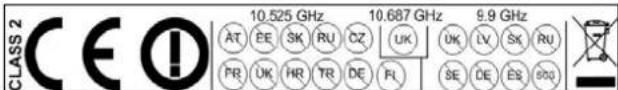
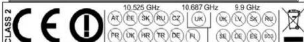
| Technologies | Passive infrared (PIR) and microwave (X-band, 9.9/10.525/10.687 GHz) |
| Sensitivity Adjustment | PIR sensitivity potentiometer + microwave intensity jumper (H/L) |
| Pet Immunity | Up to 15 kg without filter; up to 36 kg with LC-F1-15X filter |
| Temperature Compensation | Dual slope |
| Protections | Front and rear tamper, weatherproof (IP), protection against sunlight, wind (30 m/s), snow, rain, RF and EMI interference |
| Alarm Output | Form C relay (NC/C/NO), 28 VDC 0.1 A, duration 2 sec (±0.5) |
| Operating Temperature | -35°C to +55°C |
| Maintenance | No maintenance required |
| Security | Intrusion detection, alarm, tamper (cover removal and base removal) |
| Accessories / Spare Parts | Outdoor mounting bracket LC-B1-15X; Curtain/long range lens LC-L3-15X; Pet filter LC-F1-15X |
| Warranty | 12 months (material and manufacturing defects) |
| Compliance | R&TTE Directive (1999/5/EC), EMC, Low Voltage, RoHS; EN300440, EN301489, EN50130, FCC, IC |
Frequently Asked Questions - LC151 DSC
User questions about LC151 DSC
0 question about this device. Answer the ones you know or ask your own.
Ask a new question about this device
Download the instructions for your Motion detector in PDF format for free! Find your manual LC151 - DSC and take your electronic device back in hand. On this page are published all the documents necessary for the use of your device. LC151 by DSC.
USER MANUAL LC151 DSC
Dual-Tech Motion Sensor (Single PIR & Microwave) with adjustable Pet Immunity
INSTALLATION INSTRUCTIONS
& USER MANUAL
natural_image
Technical line drawing of a mechanical device with no visible text or symbolsP/N: 7131720 ver.B
1 General.... 3
2 Features 3
3 Assembly description....4
4 Detection Pattern.... 5
5 Selecting mounting location....7
6 Detector Installation....8
7 Terminal Block Connections.... 10
7.1 Wire Size Requirements.... 10
8 Settings & Adjustments 11
8.1 Detection beam direction.... 11
8.2 Detection beam range setting 11
8.3 Sensitivity Adjustment.... 11
8.4 Indications setting.... 12
9 Operation....14
10 Test procedure 14
11 Accessories.... 14
12 Specifications 15
1 General
The LC-151 is a unique motion detector utilizing a single (two elements) passive infra-red element and Microwave technology for use outdoors in harsh environments.
The LC-151 is designed for outdoor use in the most severe and climatic conditions and may also accommodate pets with the addition of optional pet immunity lenses.
EN
High reliability is achieved by combining both dual tech hardware with highly sophisticated software, greatly reducing the possibility of false alarms.
The active elements are comprised of a single (two elements) PIR and advanced Microwave detector inside a stylish, rigid plastic body.
These special optics combined with a Microwave Doppler sensor assures elimination of “false alarms” while maintaining high security standards for the detection of human intruders into the protected area.
The detection sensitivity and range is controlled by a potentiometer allowing fine tuning, so that the correct detection pattern will be set for every installation.
The LC-151 is designed to protect large areas and can easily be installed on walls in order to provide a solid protection of the area while rejects interferences from birds and small animals due to the optional “PET MASK” optics.
2 Features
- Microwave detection based on Doppler concept.
• N.O. & N.C. relays switched at the same time.
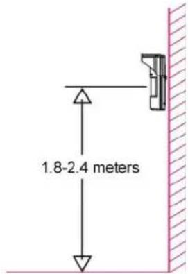
• Installation height is calibration free from 1.8m to 2.4m (5.9 to 7.8 ft) - Pet Immune up to 15kg (33lb) without pet immunity lens or up to 36kg (80lb) when using supplied LC-F1-15X pet immunity lens.
• PIR sensitivity adjustment. - MW intensity selection.
• Temperature compensation. - Microcontroller signal processing.
- Front and back tamper protection.
- Unique waterproof and sealed plastic design.
• Detection Range: Up to 15m (49 ft) - Detects human intruders walking or running.
- No maintenance required.
• High RFI/EMI Immunity. - Protection from: direct sunlight, wind up to 30 m/sec (98 ft/sec), snow and rain, small animals, removal of top cover and removal from mounting bracket.
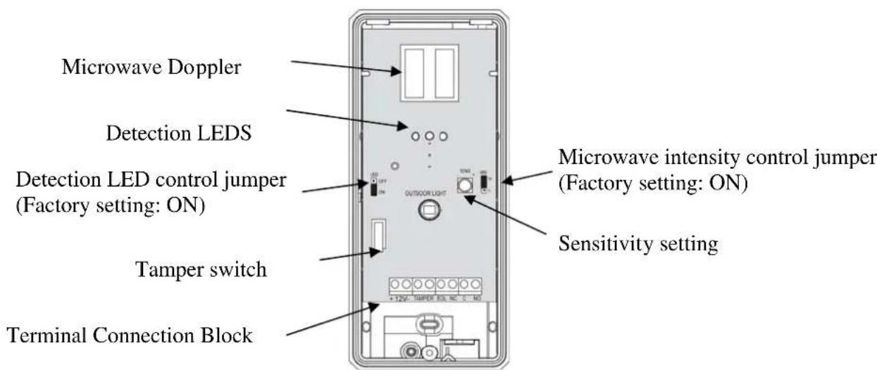
3 Assembly description
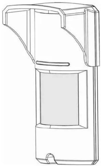
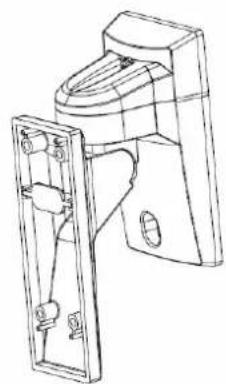
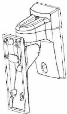
The LC-151 is a robust yet small detector which includes a large LED indicator that can be easily observed from long distances to provide indication of intrusion. Using the supplied mounting bracket, the LC-151 can be easily mounted to walls using the provided mounting screws. For installations requiring the detection beam to be adjusted horizontally or vertically to obtain the desired field of protection use the LC-B1-15X Outdoor Mounting Bracket pictured below. (not included)
natural_image
Technical line drawing of a device housing with internal components and mounting brackets (no text or symbols)LC-151 Outdoor Motion Detector
natural_image
Technical line drawing of a mechanical device with no visible text or symbolsLC-B1-15X Outdoor Mounting Bracket
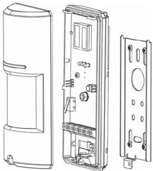
The LC-151 consists of two detection elements:
- PIR element
- Microwave element
The following drawing shows all internal elements:
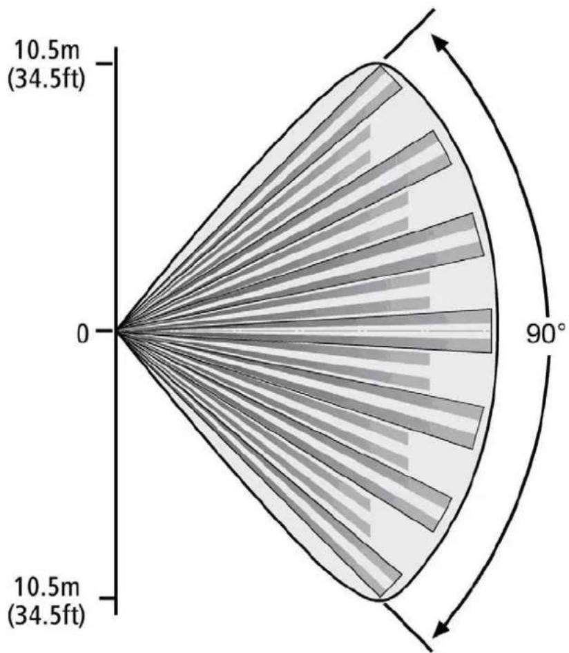
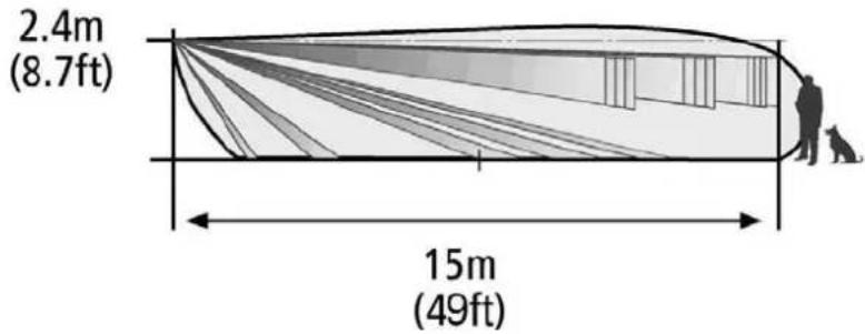
4 Detection Pattern
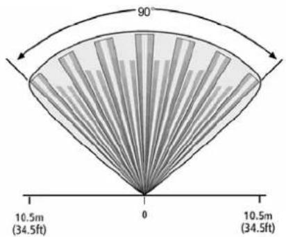
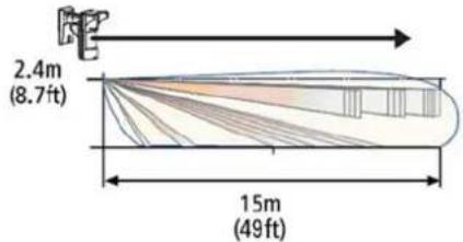
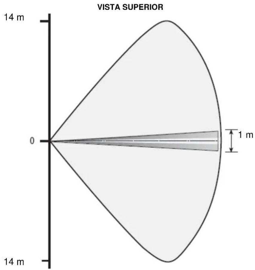
The LC-151 has a 90° top view PIR and MW detection pattern with over 15m (49 ft) detection distance (when installed at 2.4m (7.8 ft) above the ground surface).
EN
Standard Lens
TOP VIEW
radar
| Angle (°) | Value | | --------- | --------- | | 0 | 0 | | 90 | 10.5 | | 180 | 10.5 | | 270 | 10.5 | | 360 | 10.5 | | 450 | 10.5 | | 540 | 10.5 | | 630 | 10.5 | | 720 | 10.5 | | 810 | 10.5 | | 900 | 10.5 | | 1000 | 10.5 | | 1100 | 10.5 | | 1200 | 10.5 | | 1300 | 10.5 | | 1400 | 10.5 | | 1500 | 10.5 | | 1600 | 10.5 | | 1700 | 10.5 | | 1800 | 10.5 | | 1900 | 10.5 | | 2000 | 10.5 | | 2100 | 10.5 | | 2200 | 10.5 | | 2300 | 10.5 | | 2400 | 10.5 | | 2500 | 10.5 | | 2600 | 10.5 | | 2700 | 10.5 | | 2800 | 10.5 | | 2900 | 10.5 | | 3000 | 10.5 | | 3100 | 10.5 | | 3200 | 10.5 | | 3300 | 10.5 | | 3400 | 10.5 | | 3500 | 10.5 | | 3600 | 10.5 | | 3700 | 10.5 | | 3800 | 10.5 | | 3900 | 10.5 | | 4000 | 10.5 | | 4100 | 10.5 | | 4200 | 10.5 | | 4300 | 10.5 | | 4400 | 10.5 | | 4500 | 10.5 | | 4600 | 10.5 | | 4700 | 10.5 | | 4800 | 10.5 | | 4900 | 10.5 | | 5000 | 10.5 | | 5100 | 10.5 | | 5200 | 10.5 | | 5300 | 10.5 | | 5400 | 10.5 | | 5500 | 10.5 | | 5600 | 10.5 | | 5700 | 10.5 | | 5800 | 10.5 | | 5900 | 10.5 | | 6000 | 10.5 | | 6100 | 10.5 | | 6200 | 10.5 | | 6300 | 10.5 | | 6400 | 10.5 | | 6500 | 10.5 | | 6600 | 10.5 | | 6700 | 10.5 | | 6800 | 10.5 | | 6900 | 10.5 | | 7000 | 10.5 | | 7100 | 10.5 | | 7200 | 10.5 | | 7300 | 10.5 | | 7400 | 10.5 | | 7500 | 10.5 | | 7600 | 10.5 | | 7700 | 10.5 | | 7800 | 10.5 | | 7900 | 10.5 | | 8000 | 10.5 | | Note: The angle '9o' indicates the total sum of all other sectors for the data point at the center of the chart.SIDE VIEW
The LC-151 can differentiate between pets and human bodies and alert accordingly by utilizing microwave movement detection combined with a PIR detection beam.
An intrusion is defined by the PIR detection beam being crossed and a microwave detection occurring, causing an alarm.
No alarm will be generated if only the PIR detection beam is crossed or if only a microwave detection occurs.
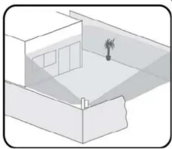
5 Selecting mounting location
The installation of the LC-151 requires a solid, level base for the mounting bracket and must be located in a manner that when the detector is mounted, it is facing the center of the
desired detection zone.
It is recommended that the detector will face a solid border limiting the detection area, such as the building structure or fencing wall, to avoid undesired detection range.
The protected area must be free from obstacles like walls, fences, trees, ditches and other microwave detectors.
natural_image
Isometric line drawing of a room with a small tree on the wall (no text or symbols)EN
Choose a location most likely to intercept an intruder according to detection pattern on page 5.
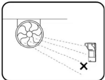
Avoid the following Installation Locations:
- Facing direct sunlight.
- Facing areas subject to rapid temperature changes.
- Mounted at more than 10^ from the vertical or horizontal plane.
- Facing metal doors.
- Near direct sources of heat or airflow.
- Clear all physical obstacles from the detection area (e.g. plants, laundry, etc.)
- Clear all light reflecting surfaces from the detection area, including puddles or other standing water.
- Avoid installation on the following types of ground: Thick vegetation, Grass (un-mown), Water, Sand and Metal.
natural_image
Diagram showing a fan emitting beams to a wall-mounted device with a cross mark indicating alignment (no text or symbols present)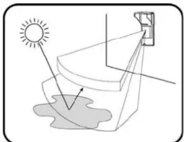
natural_image
Diagram showing sunlight illuminating a curved surface with a small object nearby (no text or symbols)NOTES:
- Recommended installation height is 2.1m (6.8 ft).
- The PIR sensor detects motion crossing the beam; it is less sensitive detecting motion towards the detector.
- The LC-151 performs best when provided with a constant and stable environment.
- In order to ensure suitable operation of the LC-151, the type of ground should be one of the following: Asphalt concrete, Cement, Soil, Clay, Gravel or Grass (mown).
- Sensitivity adjustment may be required upon extreme temperature changes.
Extremely high temperature will reduce detection range. Extremely low temperature will increase detection range.
Choose proper installation location to avoid resetting.
6 Detector Installation
Important! Prior to installation, read both "Operation" and "Selecting the mounting location" sections carefully.
- Install the detector in such manner that the intruder is most likely to cross the detection area from side to side.
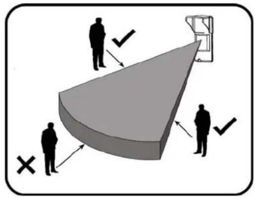
- The detector is to be installed at height of 1.8 to 2.4 meters (5.9 to 7.8 ft), ideally 2.1m (6.8 ft)
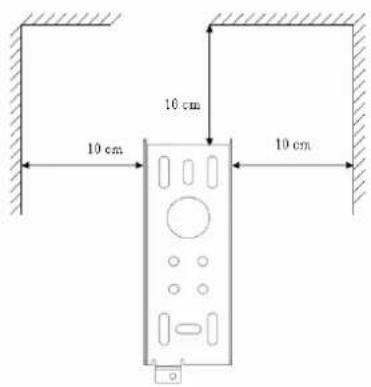
- Make sure to attach the metal bracket to a leveled straight and firm wall, leaving 10cm (3.9 inches) from the top and 10cm (3.9 inches) from both sides, for easy installation and maintenance.
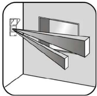
- Placing the detector on perpendicular wall is required for guarding a side window opening. Alternately the LC-B1-15X Outdoor Mounting bracket can be installed on the same wall, allowing the detector beam to be rotated towards the window.
natural_image
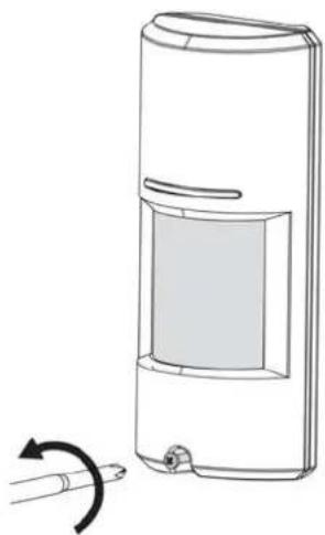
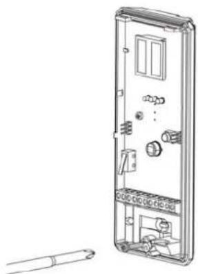
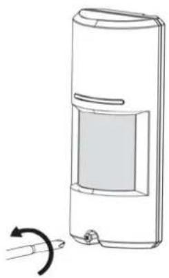
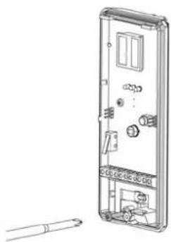
3D diagram of a room corner with a wall-mounted monitor and two angled beams, no text or symbols present- Open the detector unwinding the bottom screw.
natural_image
Diagram of a handheld device with a scroll wheel and a curved arrow indicating rotation (no text or symbols)- Release the rear metal bracket by unwinding internal bottom screw.
natural_image
Technical line drawing of a device interior with labeled components and a separate cylindrical component (no text or symbols present)7. Release the detector body from the metal bracket by pulling the detector up and out.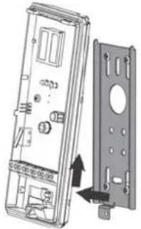 | 8. Attach the rear bracket to the wall using mounting screws.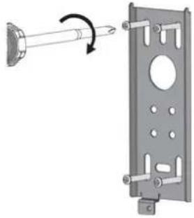 |
9. Insert wires through provided access hole and wiring channels.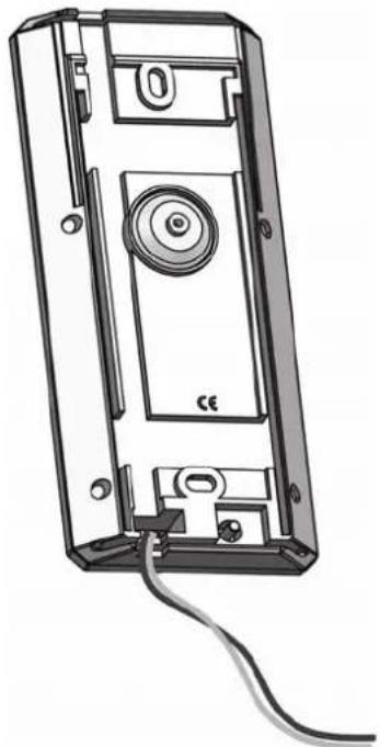 | 10. Attach the sealing sponge pad to the wire opening from the rear side after the wires have been connected and prior to final product affixing to the mounted bracket.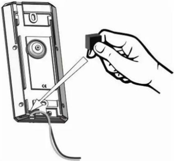 |
11. Place the detector on the mounting bracket from top side down and then lock the screw at the bottom.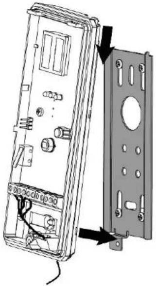 | 12. If Pet immunity up to 15kg (33lb) is desired do not install the LC-F1-15X mechanical pet filter.If Pet immunity up to 36kg (80lb) is desired install the LC-F1-15X mechanical pet filter.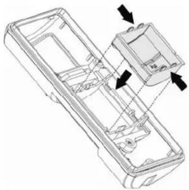 |
7 Terminal Block Connections
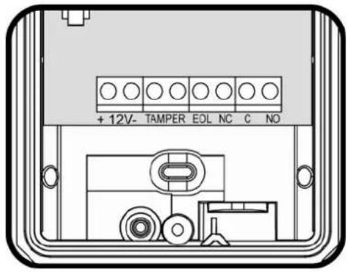
Terminal 1 - Marked “+” (+12V) - Connect to a positive Voltage of 9.6 -16Vdc source (usually from the control panel)
Terminal 2 - Marked “-” (GND) - Connect to the ground of the control panel.
Terminals 3 & 4 - Marked "TAMPER" - If a Tamper function is required connect these Terminals to a normally closed 24-Hour Tamper Zone on the control panel.
If the top cover of the detector is opened or the detector is detached from installation wall, an immediate alarm signal will be sent to the control panel.
Terminal 5 - Marked "EOL" - End of line – optional terminal for end of line resistors connections.
Terminals 6, 7 & 8 - Marked “NC / C / NO” - These are the output relay contacts of the detector. Connect to a zone input on the control panel. When an intruder is detected, alarm relays (N.C. and N.O.) will switch for 1.8 sec.
7.1 Wire Size Requirements
Use #22 AWG or larger wires. Use the following table to determine required wire gauge and length.
| Wire Length [m] | 205 | 310 | 510 | 870 | ||
| Wire Length [ft.] | 800 | 1200 | 2000 | 3400 | ||
| Wire Gauge [#] | 22 | 20 | 18 | 16 |
8 Settings & Adjustments
8.1 Detection beam direction
The LC-151 detection beam direction is fixed. As a result, it is recommended to face the intrusion area with the detector.

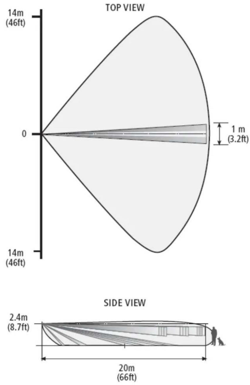
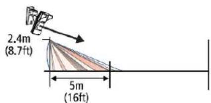
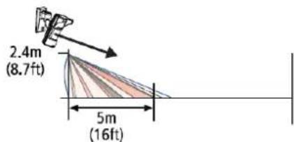
8.2 Detection beam range setting
The detection range may be set by tilting the detector while installed using the LC-B1-15X Outdoor Mounting Bracket. The range may vary between 5 and 15m (16ft to 49ft).
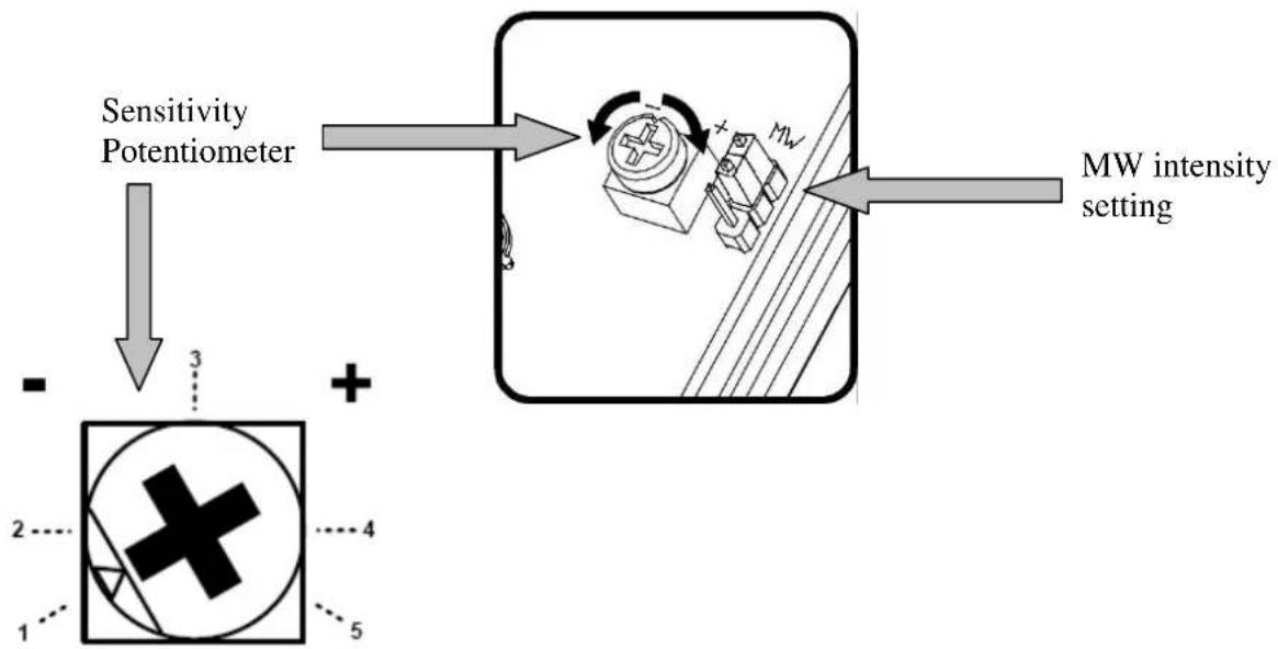
8.3 Sensitivity Adjustment
The calibration of detector sensitivity is performed by a single sensitivity potentiometer and a Microwave intensity jumper. Changing the PIR sensitivity and microwave intensity affects immunity to environmental noises and allows the detector to operate without nuisance alarms in noisier environments. The microwave intensity jumper is marked with "H" (high) and "L" (low) settings. The sensitivity potentiometer is marked with "-" to "+". Position "-" is the minimum sensitivity and position "+" is the maximum sensitivity. The PIR sensitivity and microwave intensity must be adjusted according to environmental conditions as follows:
flowchart
graph TD
    A["Sensitivity Potentiometer"] --> B["Device with MW"]
    B --> C["MW intensity setting"]
    D["Input 1: Circle with cross symbol"] --> E["+"]
    E --> F["Output 2: Cross symbol"]
    G["Input 3: Down arrow"] --> H["+"]
    H --> I["Output 4: Down arrow"]
    J["Input 5: Down arrow"] --> K["+"]
    K --> L["Output 5: Down arrow"]
| Environment type Potentiometer position MW jumper position | |||
| Low risk At position 5 |  | [HKX8] |  |
| Risk Between positions |  | [S39T] |  |
| 3 and 4 | — | ||
| High risk Between positions |  | [HVAC] | [HXXX] |
| 4 and 5 | |||
| Very high risk Between positions | [KSZH] | [2CTB] | [6AHO] |
| 3 and 4 | |||
| Noisy area Between positions |  | - | [0ZK6] |
| 2 and 3 | |||
| Extremely Noisy area At position 1 |  | -[GT36] | [032A] |
Note: Adjust sensitivity according to environmental conditions!
- Low risk: very stable environment without interference from parking garages, parking space, playgrounds, football fields, service roads, etc.
- Risk: Stable environment with some trees, bushes, flowerpots, planters, etc.
- High risk: Unstable environment with different types of vegetation and grass and puddles.
- Very high risk: Unstable environment with winds and small pets, rats, mice, birds.
- Noisy area: Unstable environment with vegetation and water sources like swimming pool, lake, canal, weeds as well as small pets like cats and rabbits.
- Extremely Noisy are very unstable environment subjected to wind, snow, rain, with vegetation, water and large pets like dogs.
For Example:
If the detector is used in a space which contains several bushes and a swimming pool the environmental conditions should be considered a "Noisy Area"
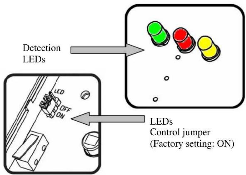
8.4 Indications setting
The LC-151 has 3 LEDs that each points at different indication:
- Green LED indicates PIR detection.
- Yellow LED indicates Microwave detection.
- Red LED – Indicates an alarm (logic AND of both Mircowave and PIR).
When the LED jumper is in the "ON" position the LEDs will be active. When the LED jumper is in the "OFF" position, the LEDs will not activate.
EN
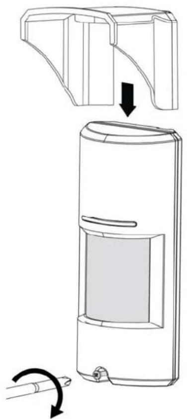
- Place the top cover to the base and close it using the bottom screw.
- Place the top visor in place.
natural_image
Diagram of a device with a handle and internal panel, showing a step-by-step assembly (no text or symbols)9 Operation
Note! Connect the LC-151 to a positive Voltage output of 9.6 -16Vdc source.
Use only a listed power limited source.
The detector shall be provided with minimum of 4 hours of standby power from either a listed compatible control unit or power supply.
- The detector begins a 30 second warm up period once connected to power.
- If the LEDs are enabled, they will sequentially flash from left to right for the duration of the 30 seconds warm up period.
- Once the warm up period is complete, the detector is ready for use.
10 Test procedure
Walk Test
IMPORTANT NOTE: Once installed, the unit should be thoroughly tested to verify proper operation and coverage. After installation, the unit should be tested annually by the installer. The end user should be instructed on how to perform a weekly walk test.
Make sure LEDs control is set to "ON"
Ensure the detector has completed the 30 second warm up period before walk testing.
Make sure that the protected area is cleared of all people.
Create motion in the entire area where coverage is desired by walking perpendicular to the detection pattern.
Look at the LEDs whenever motion is detected - all LEDs are turned ON.
Allow 5 sec. between each test for the detector to stabilize.
Walk across the entire area where coverage is desired. Should the coverage be incomplete, readjust sensitivity or relocate the detector.
Once coverage is as desired the LEDs should be disabled.
11 Accessories
| Device | Part | Numbe |
| Outdoor Mounting bracket LC-B1-15X | ||
| PIR Corridor/Long Range Lens LC-L1-15X | ||
| 36kg (80lb) PET Filter LC-F1-15X |
12 Specifications
| Detection Method PIR AND MW | |
| Microwave Frequency X-band (9.9GHz / 10) | 525GHz / 10.687GHz) |
| Power Input 9.6 to 16Vdc | |
| Current Draw Active: 24mA ( ± 5%); Standby: | 21mA ( ± 5%) |
| Temp Compensation Dual slope temperature compensation | |
| Alarm Period 2 sec ( ± 0.5sec) | |
| Alarm Outputs | Form C (NC, NO, Common)28Vdc 0.1 A with 10 Ohm |
| Tamper Switch(s) | Two SwitchesN.C 28Vdc 0.1 A with 10 Ohm Series protection resistorsOpens when cover is removed from unit's base or if base is removed from wall |
| Warm up Period 30sec ( ± 5sec) | |
| LED Indicator | Green LED for PIR detectionYellow LED for Microwave detectionRed LED for alarm conditionAll LEDs are ON during ALARM |
| RF Immunity 10 V/m plus 80% AM from 80 MHz to 2GHz | |
| ElectroStatic Immunity 6kV contact, 8kV air | |
| Transient Immunity 1kV | |
| Operation Temp -35°C ~ +55°C (-31°F ~ +131°F) | |
| Dimensions 160 mm x 70 mm x 45 mm (6.3" x 2.7" x 1.7") | |
| Weight 210gr. (0.45 lb) | |
| European directives | RTTE directive:1999/5/ECEMC directive: 2004/108/ECLow Voltage directive: 2006/95/ECRoHS directive: 2002/95/EC |
| European standards requirements: | EN300 440-2; EN301 489-1; EN50130-4 +A1 +A2; EN61000-6-3+A11EN60950-1EN50131-1 / EN50131-2-4 / EN50130-5 |
| USA & Canada | 47CFR part 15, subpart C, section 15.245; 47CFR part 15, subpart BRSS210; ICES-003 |
| Protection Degree | IEC 60529: IP 65 |
• Specifications are subject to change without prior notice.
FCC COMPLIANCE STATEMENT
FCC ID: F5309LC151
CAUTION: Changes or modifications not expressly approved by Digital Security Controls could void your authority to use this equipment.
This equipment generates and uses radio frequency energy and if not installed and used properly, in strict accordance with the manufacturer's instructions, may cause interference to radio and television reception. It has been type tested and found to comply with the limits for Class B device in accordance with the specifications in Subpart "B" of Part 15 of FCC Rules, which are designed to provide reasonable protection against such interference in any residential installation. However, there is no guarantee that interference will not occur in a particular installation. If this equipment does cause interference to television or radio reception, which can be determined by turning the equipment off and on, the user is encouraged to try to correct the interference by one or more of the following measures:
- Re-orient the receiving antenna
- Relocate the alarm control with respect to the receiver
- Move the alarm control away from the receiver
- Connect the alarm control into a different outlet so that alarm control and receiver are on different circuits.
If necessary, the user should consult the dealer or an experienced radio/television technician for additional suggestions. The user may find the following booklet prepared by the FCC helpful: "How to Identify and Resolve Radio/Television Interference Problems". This booklet is available from the U.S. Government Printing Office, Washington, D.C. 20402, Stock # 004-000-00345-4.
INDUSTRY CANADA COMPLIANCE STATEMENT
IC:160A-LC151
The term 'IC:' before the radio certification number only signifies that Industry Canada technical specifications were met.
RTTE Compliance Statement:
Hereby, DSC, declares that this device is in compliance with the essential requirements and other relevant provisions of Directive 1999/5/EC.
The complete R & TTE Declaration of Conformity can be found at www.dsc.com/intl/rttedirect.htm.
Limited Warranty
Digital Security Controls warrants that for a period of 12 months from the date of purchase, the product shall be free of defects in materials and workmanship under normal use and that in fulfillment of any breach of such warranty, Digital Security Controls shall, at its option, repair or replace the defective equipment upon return of the equipment to its repair depot. This warranty applies only to defects in parts and workmanship and not to damage incurred in shipping or handling, or damage due to causes beyond the control of Digital Security Controls such as lightning, excessive voltage, mechanical shock, water damage, or damage arising out of abuse, alteration or improper application of the equipment.
The foregoing warranty shall apply only to the original buyer, and is and shall be in lieu of any and all other warranties, whether expressed or implied and of all other obligations or liabilities on the part of Digital Security Controls. Digital Security Controls neither assumes responsibility for, nor authorizes any other person purporting to act on its behalf to modify or to change this warranty, nor to assume for it any other warranty or liability concerning this product.
In no event shall Digital Security Controls be liable for any direct, indirect or consequential damages, loss of anticipated profits, loss of time or any other losses incurred by the buyer in connection with the purchase, installation or operation or failure of this product.
Motion detectors can only detect motion within the designated areas as shown in their respective installation instructions. They cannot discriminate between intruders and intended occupants.
Motion detectors do not provide volumetric area protection. They have multiple beams of detection and motion can only be detected in unobstructed areas covered by these beams. They cannot detect motion which occurs behind walls, ceilings, floor, closed doors, glass partitions, glass doors or windows. Any type of tampering whether intentional or unintentional such as masking, painting, or spraying of any material on the lenses, mirrors, windows or any other part of the detection system will impair its proper operation.
Passive infrared motion detectors operate by sensing changes in temperature. However their effectiveness can be reduced when the ambient temperature rises near or above body temperature or if there are intentional or unintentional sources of heat in or near the detection area. Some of these heat sources could be heaters, radiators, stoves, barbeques, fireplaces, sunlight, steam vents, lighting and so on.
Warning: Digital Security Controls recommends that the entire system be completely tested on a regular basis. However, despite frequent testing, and due to, but not limited to, criminal tampering or electrical disruption, it is possible for this product to fail to perform as expected.
Important Information: Changes or modifications not expressly approved by Digital Security Controls could void the user's authority to operate this equipment.
LC-151
FR
natural_image
Technical line drawing of a mechanical component or housing (no text or symbols)natural_image
Technical line drawing of a device housing with internal components and mounting holes (no text or symbols)natural_image
Technical line drawing of a mechanical device with no visible text or symbols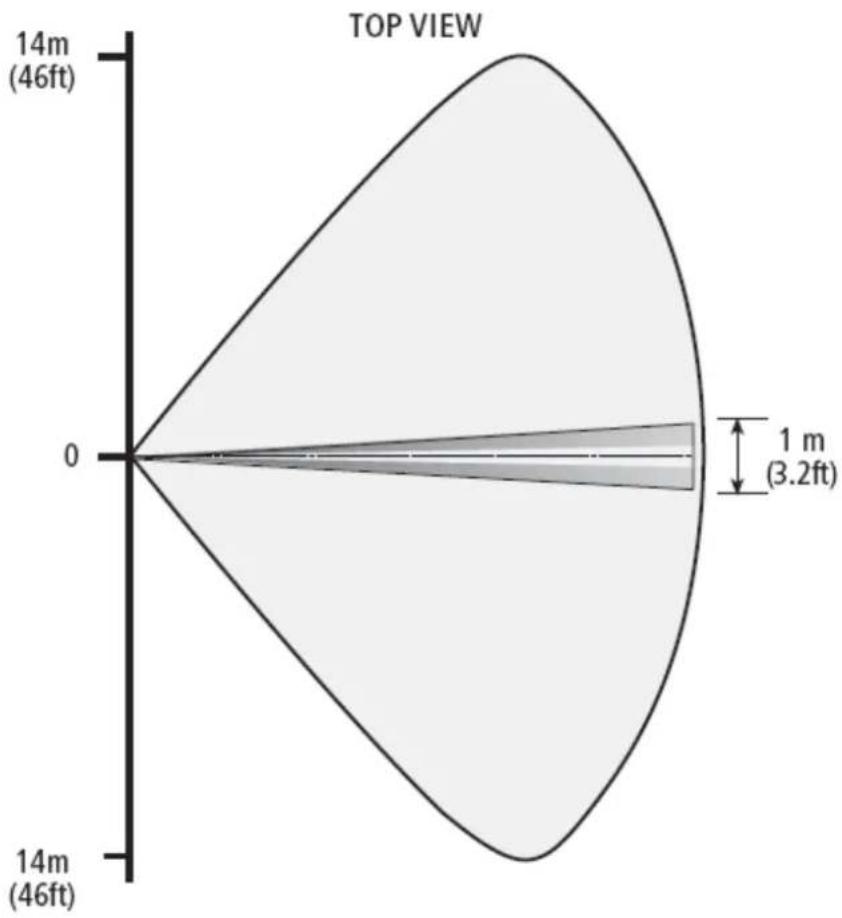
radar
| Dimension | Value | | --------- | --------- | | Top View | 14m (46ft)| | Bottom Left | 0 | | Bottom Right | 1 m (3.2ft) |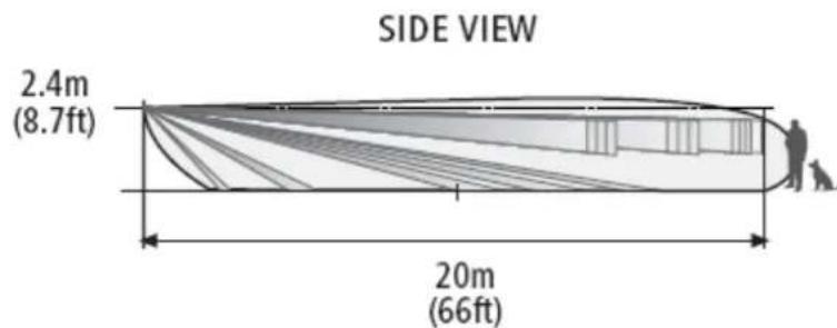
other
| Section | Height (m) | | ------------- | ---------- | | Top Section | 2.4 | | Bottom Section| 20 |natural_image
Isometric line drawing of a room with a small tree and wall, no text or symbols presentnatural_image
Diagram showing a fan emitting light rays from a wall-mounted device, with a cross symbol indicating a detection or measurement point (no text or labels present)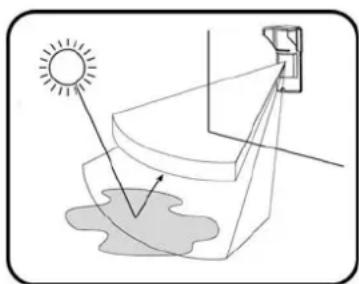
natural_image
Diagram showing sunlight entering a curved structure with a wall-mounted panel, no text or symbols presentREMARQUE :
natural_image
3D diagram of a room corner with two walls, one containing a mirror and the other a shelf, showing structural connections (no text or symbols)natural_image
Diagram of a handheld device with a scroll wheel and scroll wheel, showing a curved arrow indicating rotation (no text or symbols present)natural_image
Technical line drawing of a device rear panel with internal components and a pencil for scale (no text or symbols)FR
natural_image
Line drawing of a cylindrical device with a rectangular panel and a small protrusion, no text or symbols present.21 Fonctionnement
The complete R & TTE Declaration of Conformity can be found at www.dsc.com/intl/rttedirect.htm.
Garantie limitée
natural_image
Technical line drawing of a mechanical component or housing (no text or symbols)natural_image
Technical line drawing of a device housing with internal components and mounting holes (no text or symbols)natural_image
Technical line drawing of a mechanical device with no visible text or symbolsnatural_image
Isometric line drawing of a room with a potted plant on the wall (no text or symbols)natural_image
Diagram showing a fan emitting light rays from a device, with a cross mark indicating a specific point (no text or symbols present)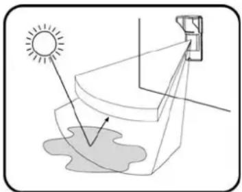
natural_image
Diagram showing sunlight illuminating a curved surface with a small object nearby (no text or symbols)OBSERVACION:
natural_image
3D diagram of a room interior with walls, shelves, and a door (no text or symbols)natural_image
Line drawing of a handheld electronic device with a scroll wheel and indicator lights, showing no text or symbols.natural_image
Technical line drawing of a device interior with labeled components and a separate cylindrical component (no text or symbols present)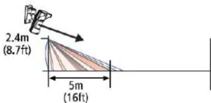
natural_image
Line drawing of a cylindrical device with a rectangular panel and a small pen beside it (no text or symbols)33 Operación
Hereby, DSC, declares that this device is in compliance with the essential requirements and other relevant provisions of Directive 1999/5/EC.
The complete R & TTE Declaration of Conformity can be found at www.dsc.com/intl/rttedirect.htm.
Garantía limitada
natural_image
Technical line drawing of a mechanical device with no visible text or symbolsnatural_image
Technical line drawing of a device housing with internal components and mounting holes (no text or symbols)Detector de movimentos para ambientes externos LC-151
natural_image
Technical line drawing of a mechanical device with no visible text or symbolsnatural_image
Diagram of a curved structure with internal diagonal lines and a small human silhouette, no text or symbols present.15 m
radar
| Angle (m) | Value | | --------- | ----- | | 0 | 0 | | 14 | 14 |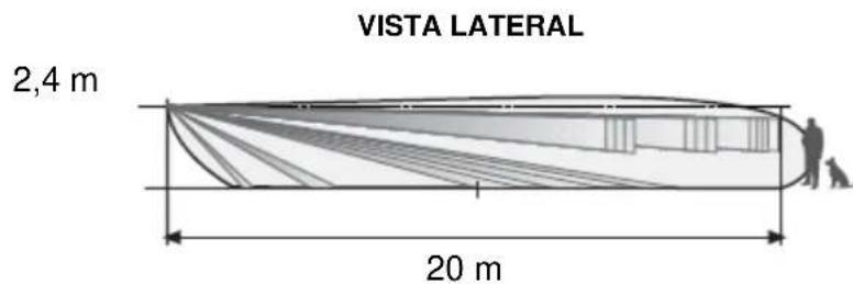
natural_image
Isometric line drawing of a room with a potted plant and a window (no text or symbols)natural_image
Diagram showing airflow from a fan to a vehicle, with a cross mark indicating a collision or failure (no text or symbols present)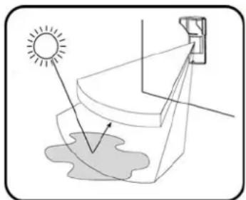
natural_image
Diagram showing sunlight illuminating a surface with a camera, no text or symbols presentOBSERVAÇÃO:
natural_image
3D diagram of a room corner with two walls, one containing a wall-mounted screen and the other showing a mirror (no text or symbols)- Abra o detector afrouxando o parafuso inferior.
natural_image
Diagram of a cylindrical device with a scroll wheel and a button, showing a curved arrow indicating rotation (no text or symbols present)- Solte o suporte de metal traseiro afrouxando o parafuso inferior interno.
natural_image
Technical line drawing of a device casing with internal components and a pen for scale (no text or symbols)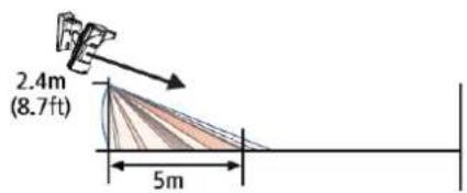

natural_image
Line drawing of a cylindrical device with a rectangular panel and a small pen inserted (no text or symbols)45 Funcionamento
Hereby, DSC, declares that this device is in compliance with the essential requirements and other relevant provisions of Directive 1999/5/EC.
The complete R & TTE Declaration of Conformity can be found at www.dsc.com/intl/rttedirect.htm.
GARANTIA LIMITADA
natural_image
Technical line drawing of a mechanical component or housing (no text or symbols)natural_image
Technical line drawing of a device interior showing internal components and housing (no text or symbols)natural_image
Technical line drawing of a mechanical device with handle and mounting bracket (no text or symbols)natural_image
Isometric line drawing of a room with a palm tree and window (no text or symbols)natural_image
Diagram showing airflow from a fan to a vehicle, with a cross mark indicating a collision or failure (no text or symbols present)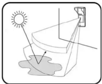
natural_image
Diagram showing sunlight illuminating a surface with a camera, no text or symbols presentNOTA
natural_image
3D diagram of a room with shelves and a wall-mounted fixture, no text or symbols presentnatural_image
Line drawing of a cylindrical device with a scroll wheel and a curved arrow indicating rotation (no text or symbols)natural_image
Technical line drawing of an open electronic device casing with internal components and a separate pencil (no text or symbols)
natural_image
Line drawing of a cylindrical device with a rectangular chamber and a small protruding rod (no text or symbols)57 Funzionamento
Hereby, DSC, declares that this device is in compliance with the essential requirements and other relevant provisions of Directive 1999/5/EC.
The complete R & TTE Declaration of Conformity can be found at www.dsc.com/intl/rttedirect.htm.