GUCE64 - Computer accessory IOGEAR - Free user manual and instructions
Find the device manual for free GUCE64 IOGEAR in PDF.
| Product Type | USB 2.0 Extender via Ethernet |
| Brand | IOGEAR |
| Model | GUCE64 |
| Category | Computer Accessory |
| Main Functions | USB port extension up to 50m via RJ45 cable |
| Connectivity | 1 USB Type B port (local), 4 USB Type A ports (remote), 2 RJ45 ports |
| Power Supply | Local unit: USB powered; remote unit: included power adapter (5V) |
| Indicator LEDs | Power (red), Device (green), Link (orange) |
| Required Cable | Cat5, Cat5e, or Cat6 (not included) |
| Supported Operating Systems | Windows Vista/7/8/8.1, Mac OS X 10.3.9+ |
| Max Devices | 4 USB 2.0 devices |
| Max Distance | 50 m (164 ft) |
| Package Contents | Local unit, remote unit, USB A/B cable, power adapter, quick start guide, warranty card |
| Dimensions (approx.) | Approximately 8 x 5 x 2 cm per unit |
| Weight (approx.) | Approximately 100 g per unit |
| Warranty | 1 year limited |
| Maintenance and Cleaning | Clean with a dry cloth, unplug before cleaning |
| Safety | FCC Class B and CE compliant |
| Spare Parts and Repairability | Not user-serviceable; contact IOGEAR support |
| General Information | Plug & Play, no driver required |
Frequently Asked Questions - GUCE64 IOGEAR
User questions about GUCE64 IOGEAR
0 question about this device. Answer the ones you know or ask your own.
Ask a new question about this device
Download the instructions for your Computer accessory in PDF format for free! Find your manual GUCE64 - IOGEAR and take your electronic device back in hand. On this page are published all the documents necessary for the use of your device. GUCE64 by IOGEAR.
USER MANUAL GUCE64 IOGEAR
1 x GUCE64 Local Unit
1 x GUCE64 Remote Unit
1 x USB Type A to B cable
1 x Power Adapter
1 x Quick Start Guide
1 x Warranty Card
System Requirements
Operating System:
- Windows Vista®, Windows® 7, Windows® 8, Windows® 8.1
• Mac OS X 10.3.9+ - USB Port
Hardware:
- USB 2.0 port
- USB 2.0 device
• Cat5, Cat5e, or Cat6 RJ45 ethernet cable
Overview
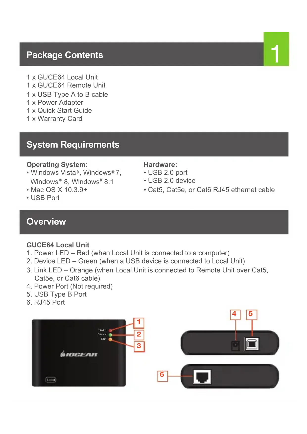
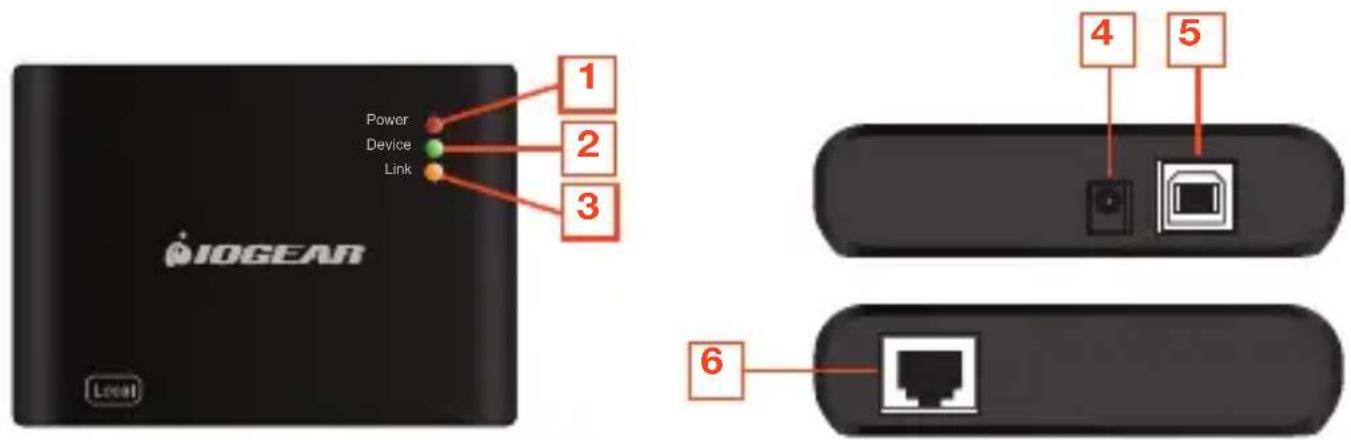
GUCE64 Local Unit
- Power LED - Red (when Local Unit is connected to a computer)
- Device LED – Green (when a USB device is connected to Local Unit)
- Link LED – Orange (when Local Unit is connected to Remote Unit over Cat5, Cat5e, or Cat6 cable)
- Power Port (Not required)
- USB Type B Port
- RJ45 Port
2
GUCE64 Remote Unit
- Power LED – Red (when Remote Unit is connected to the power adapter)
- Device LED - Green (when a USB device is connected to Local Unit)
- Link LED - Orange (when Local Unit is connected to Remote Unit over Cat5, Cat5e, or Cat6 cable)
- USB Type A Ports x 4
- Power Port
- RJ45 Port

text_image
IOGEAR Power Device Link 1 2 3 Rename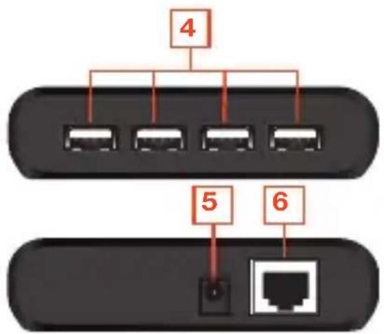
flowchart
graph TD
    A["4"] --> B["1"]
    A --> C["2"]
    A --> D["3"]
    A --> E["4"]
    A --> F["5"]
    A --> G["6"]
    H["Terminal"] --> I["1"]
    J["Terminal"] --> K["6"]
Hardware Installation
- Connect the GUCE64 BoostLinq Ethernet Local Unit to your computer, using the included USB Type A to B cable. Plug the USB A end of the cable to your computer and the USB B end to the GUCE64 Ethernet Local Unit. Power LED on Local Unit should show red.

text_image
Power Device Link IOGLAR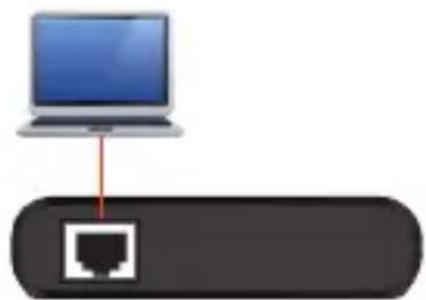
natural_image
Diagram showing a laptop connected to a network port icon (no text or labels)Local Unit
3
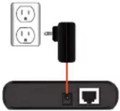
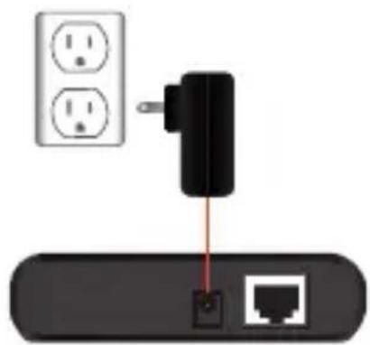
- Connect the GUCE64 BoostLinq Ethernet Remote Unit to a power source, using the included power adapter. Power LED on Remote Unit should show red.

text_image
Power Device Link BIOMEAR RenoosRemote Unit
natural_image
Diagram showing a black plug inserted into a network device with two white electrical outlets nearby (no text or symbols)-
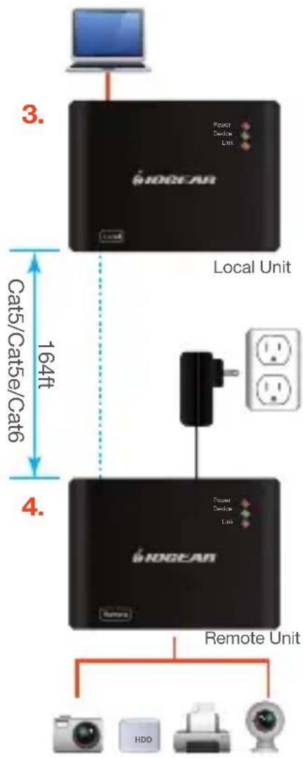
Connect the GUCE64 BoostLing Ethernet Local Unit with the Remote Unit, using a Cat5, Cat5e, or Cat6 cable (not included). Link LED on both Local and Remote Unit should show orange.
-
Plug up to four USB devices to the GUCE64 BoostLinq Ethernet Remote Unit. Device LED on both Local and Remote Unit should show green.
-
The GUCE64 is plug-n-play, no additional driver or software needed.
flowchart
graph TD
    A["Local Unit"] -->|3. Power Device Line| B["HOGEAR"]
    B --> C["Remote Unit"]
    C --> D["Device 1"]
    C --> E["Device 2"]
    C --> F["Device 3"]
    C --> G["Device 4"]
    style A fill:#000,stroke:#fff,color:#fff
    style B fill:#000,stroke:#fff,color:#fff
    style C fill:#000,stroke:#fff,color:#fff
    style D fill:#000,stroke:#fff,color:#fff
    style E fill:#000,stroke:#fff,color:#fff
    style F fill:#000,stroke:#fff,color:#fff
    style G fill:#000,stroke:#fff,color:#fff
Compliance Information
FCC Statement
This equipment has been tested and found to comply with the limits for a Class B digital device, pursuant to Part 15 of the FCC Rules. These limits are designed to provide reasonable protection against harmful interference in a residential setting. This product generates, uses, and can radiate radio frequency energy and, if not installed and used as directed, it may cause harmful interference to radio communications. Although this product complies with the limits for a Class B digital device, there is no guarantee that interference will not occur in a particular installation.
CE Compliance
This device has been tested and found to comply with the following European Union directives: Electromagnetic Capability (2004/108/EC).
Declaration of Conformity and related documents can be downloaded directly from our website: http://www.iogear.com/product/GUCE64/certifications.
Limited Warranty
This product carries a 3 Year Limited Warranty. For the terms and conditions of this warranty, please go to http://www.iogear.com/support/warranty
Register online at http://www.iogear.com/register
Important Product Information
Product Model
Serial Number
Contact
WE'RE HERE TO HELP YOU!
NEED ASSISTANCE SETTING UP THIS PRODUCT?
Make sure you:
- Visit www.iogear.com for more product information
- Visit www.iogear.com/support for live help and product support
iogear.custhelp.com
support@iogear.com
www.iogear.com
19641 Da Vinci, Foothill Ranch, CA 92610
text_image
IOGEAR Local Power Device Link 1 2 3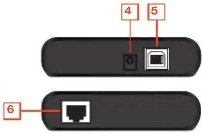
text_image
4 5 6Unité distante GUCE64
text_image
Power Device Link 1 2 3 IOGEAR Remote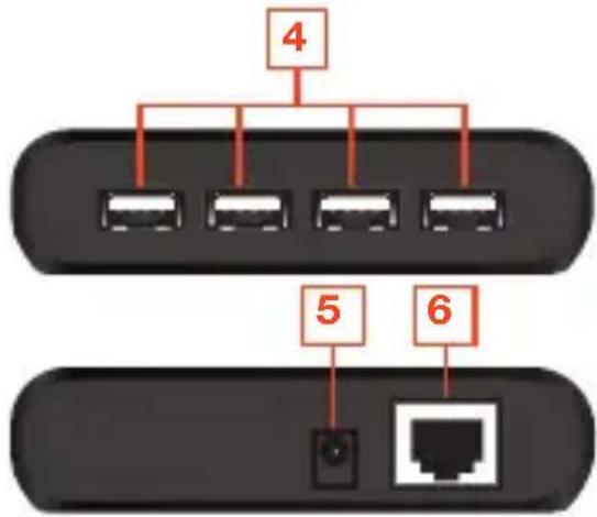
flowchart
graph TD
    A["Port 4"] --> B["Port 1"]
    A --> C["Port 2"]
    A --> D["Port 3"]
    A --> E["Port 4"]
    A --> F["Port 5"]
    A --> G["Port 6"]
    H["Terminal"] --> I["Switch"]
text_image
Power Device Link IOGEAR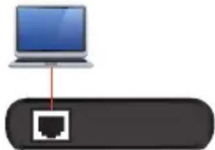
natural_image
Diagram showing a laptop connected to a network router (no text or symbols present)Local Unit
3
natural_image
Diagram showing a black plug inserted into a network device with two white power outlets, connected to a red wire (no text or symbols present)text_image
IOGEAR Power Device Link 1 2 3 Local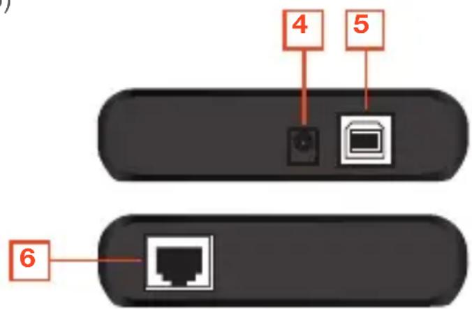
text_image
4 5 62
natural_image
Diagram showing a laptop connected to a network port icon (no text or labels)Local Unit
3
text_image
Power Device Link IOGEAR RemoveRemote Unit
natural_image
Diagram showing a black plug inserted into a network device with two white power outlets, connected to a port (no text or symbols present)text_image
3. WOGEAR Local Unit 164ft Cat5/Cat5e/Cat6 4. WOGEAR Remote Unit HDDDeclaration of Conformity and related documents can be downloaded directly from our website: http://www.iogear.com/product/GUCE64/certifications
Garantía limitada
http://www.iogear.com/support/warranty