
GCS1644 - Computer accessory IOGEAR - Free user manual and instructions
Find the device manual for free GCS1644 IOGEAR in PDF.


| Product Type | 4-Port USB KVM Switch |
| Brand | IOGEAR |
| Model | GCS1644 |
| Number of Connected Computers | 4 |
| Video Resolution Support | Up to 2048 x 1536 |
| USB Ports | 4 x USB Type B (upstream), 2 x USB Type A (downstream) |
| Audio Support | Yes, microphone and speaker pass-through |
| Switch Method | Push buttons, hotkeys, and on-screen display |
| Power Supply | DC 5V, 2.6A |
| Dimensions (W x D x H) | 247 x 76 x 23 mm |
| Weight | 0.65 kg |
| Material | Metal and plastic |
| LED Indicators | Yes, per port |
| Console Ports | VGA, USB keyboard/mouse, audio |
| Operating Temperature | 0°C to 50°C |
| Storage Temperature | -20°C to 60°C |
| Humidity | 0% to 80% RH (non-condensing) |
| Cleaning Instructions | Wipe with a dry, soft cloth. Do not use liquids or sprays. |
| Safety Compliance | FCC, CE |
| Package Contents | KVM switch, power adapter, cable set, user manual |
Frequently Asked Questions - GCS1644 IOGEAR
User questions about GCS1644 IOGEAR
0 question about this device. Answer the ones you know or ask your own.
Ask a new question about this device
Download the instructions for your Computer accessory in PDF format for free! Find your manual GCS1644 - IOGEAR and take your electronic device back in hand. On this page are published all the documents necessary for the use of your device. GCS1644 by IOGEAR.
USER MANUAL GCS1644 IOGEAR
2/4-Port Dual View Dual Link DVI KVMP Switch with Audio
GCS1642/GCS1644/GCS1642X
PART NO. M1087-g / M1088-g
www.iogear.com
©2018 IOGEAR. All Rights Reserved. PKG-M1087-g / M1088-g
IOGEAR, the IOGEAR logo, are trademarks or registered trademarks of IOGEAR. Microsoft and Windows are registered trademarks of Microsoft Corporation.
All other brand and product names are trademarks or registered trademarks of their respective holders. IOGEAR makes no warranty of any kind with regards to the information presented in this document. All information furnished here is for informational purposes only and is subject to change without notice.
IOGEAR assumes no responsibility for any inaccuracies or errors that may appear in this document.
Table of Contents
Package Contents 4
System Requirements 5
GCS1642 Overview 6
GCS1644 Overview 8
Single Stage Installation 10
Quad View (DDC Mode) 15
LED Indication 17
Port Switching 18
Port Switching via Hotkeys 19
Auto Scanning 21
Hotkey Setting Mode (HSM) 22
Mac Keyboard Emulation 24
Sun Keyboard Emulation 25
Factory Default Hotkeys Settings 26
The Firmware Upgrade Utility 27
Before you Begin 27
Starting the Upgrade 28
Upgrade Succeeded 31
Upgrade Fail 32
Federal Communications Commission 33 (FCC) Statement
CE Statement 33
Limited Warranty 34
Contact 35
Package Contents
1 x 2/4-Port Dual View Dual Link DVI KVMP Switch with Audio
2/4 x Dual Link DVI KVM Cables (2 for GCS1642 / 4 for GCS1644)
2/4 x Dual Link DVI Cables (2 for GCS1642 / 4 for GCS1644)
1 x Power Adapter
1 x Installation Guide
1 x Warranty Card
Note:
GCS1642X does not include KVM and DVI cables.
System Requirements
Console
- Two displays with DVI inputs
– A Keyboard and Mouse
Computer
– Computers with DVI outputs
- An open USB port
Optional Audio
– Analog audio connections for speakers and mic.
GCS1642 Overview
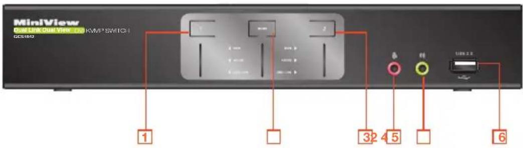
Front View
- Port 1 Pushbutton
- Mode Button
- Port 2 Pushbutton
-
Front Panel Console Mic. Connection
-
Front Panel Console Audio connection
- Front Panel USB 2.0 Peripheral Sharing Port
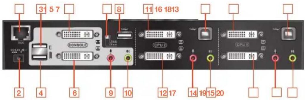
Rear View
- DDC Port (Daisy Chain Port)
- DC Power Jack
- Console USB Mouse Port
- Console USB Keyboard Port
- Console DVI Video Port B
- Console DVI Video Port A
-
DDC Switch (Host/Client)
-
USB 2.0 Peripheral Sharing Port
- Console Mic. Connection
- Console Audio Connection
- CPU2 DVI Video Port 2B
- CPU2 DVI Video Port 2A
-
CPU2 USB Connection
-
CPU2 Mic. Connection
- CPU2 Audio Connection
- CPU1 DVI Video Port 1B
- CPU1 DVI Video Port 1A
- CPU1 USB Connection
- CPU1 Mic. Connection
- CPU1 Audio Connection
GCS1644 Overview
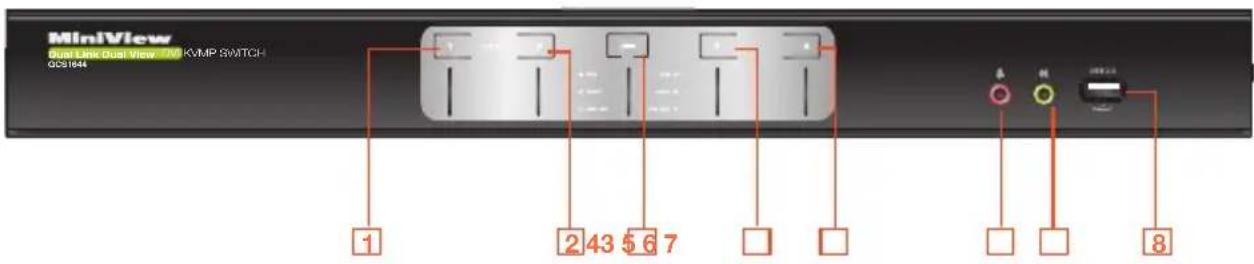
Front View
- Port 1 Pushbutton
- Port 2 Pushbutton
- Mode Button
-
Port 3 Pushbutton
-
Port 4 Pushbutton
- Front Panel Console Mic. Connection
- Front Panel Console Audio connection
- Front Panel USB 2.0 Peripheral Sharing Port
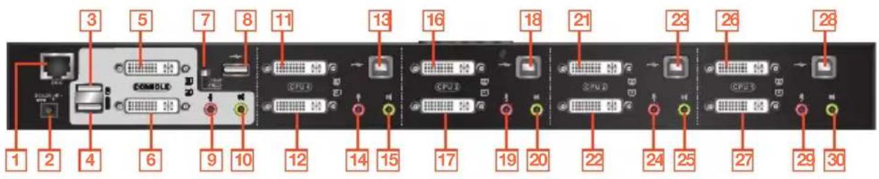
Rear View
- DDC Port (Daisy Chain Port)
- DC Power Jack
- Console USB Mouse Port
- Console USB Keyboard Port
- Console DVI Video Port B
- Console DVI Video Port A
- DDC Switch (Host/Client)
- USB 2.0 Peripheral Sharing Port
- Console Mic. Connection
-
Console Audio Connection
-
CPU4 DVI Video Port 4B
- CPU4 DVI Video Port 4A
- CPU4 USB Connection
- CPU4 Mic. Connection
- CPU4 Audio Connection
- CPU3 DVI Video Port 3B
- CPU3 DVI Video Port 3A
- CPU3 USB Connection
- CPU3 Mic. Connection
-
CPU3 Audio Connection
-
CPU2 DVI Video Port 2B
- CPU2 DVI Video Port 2A
- CPU2 USB Connection
- CPU2 Mic. Connection
- CPU2 Audio Connection
- CPU1 DVI Video Port 1B
- CPU1 DVI Video Port 1A
- CPU1 USB Connection
- CPU1 Mic. Connection
- CPU1 Audio Connection
Single Stage Installation
Step 1
Please make sure your source devices and display are powered off before you start.
Step 2
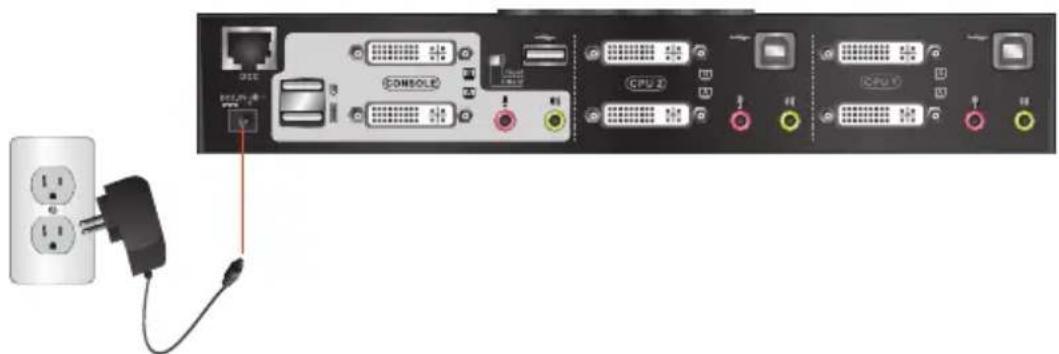
Plug the power adapter into the power outlet and connect it to the DC power jack from the KVM.
Step 3
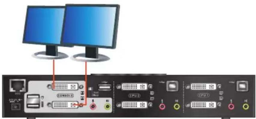
Connect the DVI cables from your monitors to the console DVI port A and B. Port A will be your main monitor and Port B will be your extended desktop monitor.
Step 4
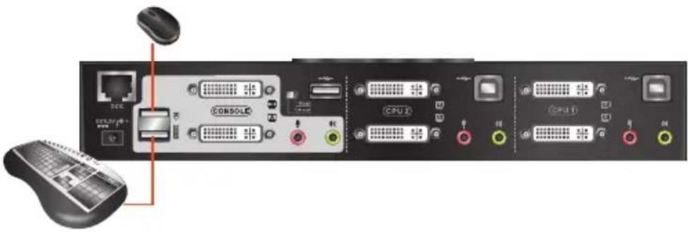
Connect your USB keyboard and mouse to the console USB keyboard port and console USB mouse port.
Step 5
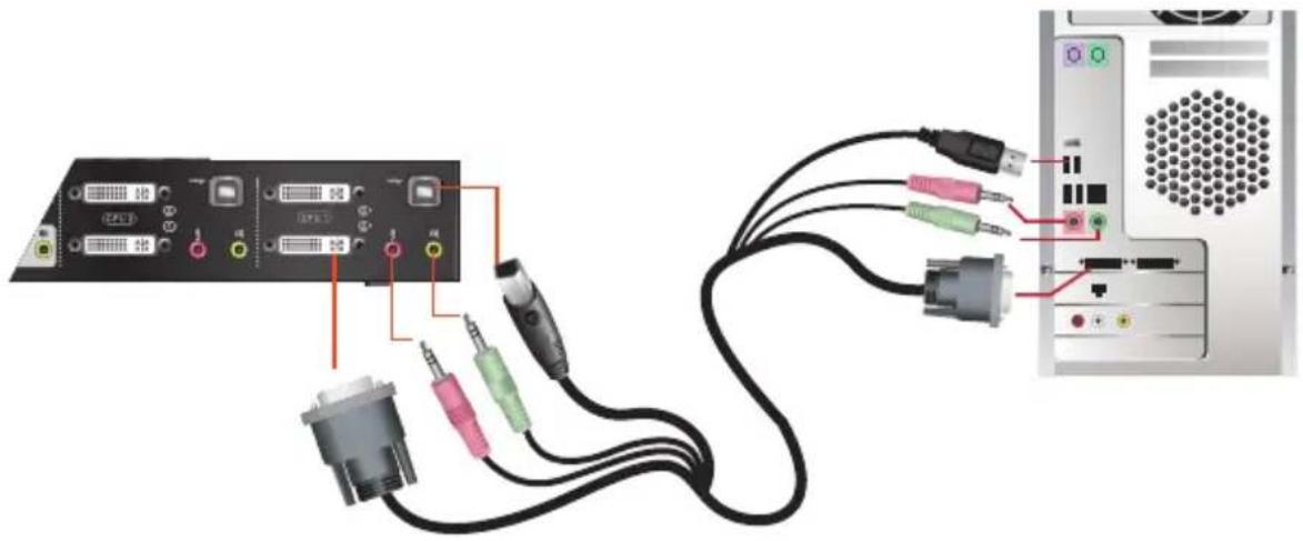
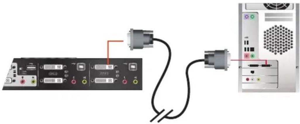
Connect a set of your Dual Link DVI KVM cable from the KVM switch to each of your computers – DVI connection from DVI Port A to the DVI output and USB connection to open USB port from your computer. Connect the audio and mic. connectors to your audio output and mic. input.
natural_image
Diagram showing connections between a computer interface with connected ports and cables (no text or symbols visible)Step 6
Connect Dual Link DVI cables from DVI Port B of the KVM to your second DVI output of your computers.
natural_image
Diagram showing connection between a server rack and an Ethernet cable, with no visible text or symbols.Final Step
Turn on your source devices.
Quad View (DDC Mode)
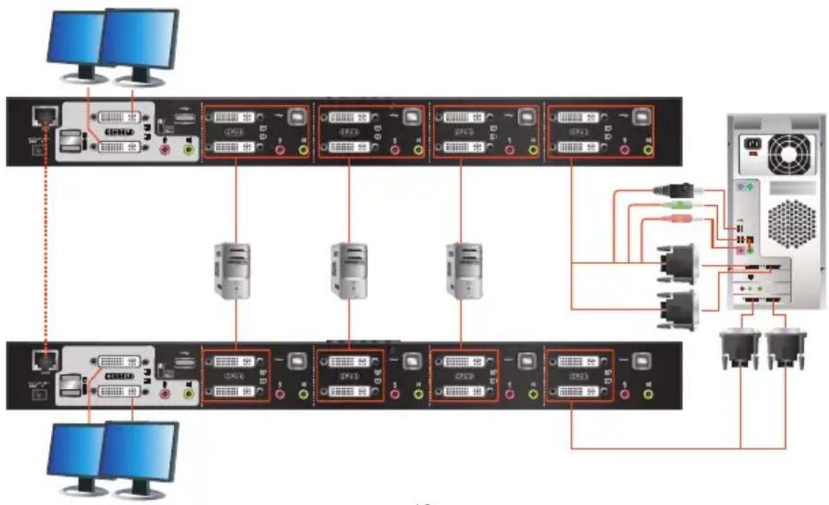
To expand your installation from Dual View displays to Quad view displays, you can use the DDC Mode port to connect two GCS1642 / GCS1644 units together. After doing so, you will be able to configure the quad displays video settings on the computer in extended mode or Mirrored mode.
To set up DDC mode, power off all devices, refer to the installation diagram on the next page.
- Connect all the computers to the Host as described in Hardware Setup, Cable Connection on page 18.
- On the Client, using two custom DVI Dual Link cables, plug the DVI connectors into the DVI sockets A and B in the same KVM port section of the switch.
- At the other end of the two custom DVI Dual Link cables, plug the monitor cable into the respective ports on the computer.
- Repeat steps 2 and 3 for all computers.
- On the rear of the second GCS1644, set the DCC switch to Client.*
- On the rear of the primary GCS1644, set the DCC switch to Host.
- Plug the console monitors into the DVI console ports located on the Host's and Client's rear panel.
- Using an RJ-45 cable, connect the DCC port of the Host to the DCC port of the Client.
- Power up the installation: plug in the power cord for the Host and Client, then power on both. After both units are up, power on the computer/video source devices.
Note:
- In DCC mode the Client's front panel pushbuttons are disabled and it takes all commands directly from the Host.
- Setting the DCC switch to Client will disable all front panel pushbuttons on that switch.
flowchart
graph TD
    A["PCs"] --> B["PC1"]
    A --> C["PC2"]
    A --> D["PC3"]
    A --> E["PC4"]
    A --> F["PC5"]
    B --> G["Computer 1"]
    C --> H["Computer 2"]
    D --> I["Computer 3"]
    E --> J["Computer 4"]
    F --> K["Computer 5"]
    G --> L["Server"]
    H --> L
    I --> L
    J --> L
    K --> L
    L --> M["Power Supply"]
    style A fill:#f9f,stroke:#333
    style B fill:#ccf,stroke:#333
    style C fill:#ccf,stroke:#333
    style D fill:#ccf,stroke:#333
    style E fill:#ccf,stroke:#333
    style F fill:#ccf,stroke:#333
    style G fill:#dfd,stroke:#333
    style H fill:#dfd,stroke:#333
    style I fill:#dfd,stroke:#333
    style J fill:#dfd,stroke:#333
    style K fill:#dfd,stroke:#333
    style L fill:#dfd,stroke:#333
LED Indication
| LED Description | ||
| Mode Orange Shows the pushbutton mode that the KVM is in | ||
| Online / Selected Dim Green A device is connected to the KVMP switch but the port is not on focus | ||
| Audio Green The specific port has focus on the audio | ||
USB Link Green The specific port has focus on the USB peripheral sharing ports
Port Switching
Simply press the front panel Pushbutton from the multimedia KVMP switch or trigger hotkeys from your keyboard.
Port Switching via Front Panel Pushbutton
| Function Description | |
| Switch all focus (KVM, audio and USB) to a specific port | Press the correspond push button once for the desire port that you wish to switch focus to. |
| Switch KVM focus to a specific port Press | the Mode button once (Orange LED will show you are in KVM Mode), then press the correspond push button for the desire port that you wish to switch focus to. |
| Switch audio focus to a specific port Press | the Mode button twice (Orange LED will show you are in Audio Mode), then press the correspond push button for the desire port that you wish to switch focus to. |
| Switch USB focus to a specific port Press | the Mode button three times (Orange LED will show you are in USB Mode), then press the correspond push button for the desire port that you wish to switch focus to. |
Port Switching via Hotkeys
Port Switching via Hotkeys
Hotkeys Description
[Scroll Lock] [Scroll Lock] [Enter] Switch all focus (KVM, audio and USB) to the next port
[Scroll Lock] [Scroll Lock] [n] [Enter] Switch all focus (KVM, audio and USB) to port n*
[Scroll Lock] [Scroll Lock] [k] [Enter] Switch KVM focus to the next port
[Scroll Lock] [Scroll Lock] [n] [k] [Enter] Switch KVM focus to port n*
[Scroll Lock] [Scroll Lock] [s] [Enter] Switch audio focus to the next port
[Scroll Lock] [Scroll Lock] [n] [s] [Enter] Switch audio focus to port n*
[Scroll Lock] [Scroll Lock] [u] [Enter] Switch USB focus to the next port
[Scroll Lock] [Scroll Lock] [n] [u] [Enter] Switch USB focus to port n*
Continue next page
Port Switching via Hotkeys
[Scroll Lock] [Scroll Lock] [n] [k] [u] [Enter] Switch KVM and USB focus to port n*
[Scroll Lock] [Scroll Lock] [n] [k] [s] [Enter] Switch KVM and audio focus to port n*
[Scroll Lock] [Scroll Lock] [n] [u] [s] [Enter] Switch USB and audio focus to port n*
*Note: n is an interval that stands for the Port number
k stands for KVM focus
s stands for audio focus
u stands for USB focus
Port Switching via Mouse
Mouse Port Switching allows you to use the mouse wheel button (clicking it twice) to switch between ports. Mouse Emulation must be enabled in order for Mouse Port Switching to work. To enable mouse port switching invoke HSM and press [W] (default setting is off)
Auto Scanning
You can either activate Autoscan Mode via front panel push button or hotkeys.
| Function Description | |||
| Auto Scan | Front panel pushbutton | Press and hold port 1 and port 2 Pushbutton simultaneously for 2 seconds to activate Autoscan Mode* | |
| Hotkeys | [Scroll Lock] [Scroll Lock] [a] [Enter] | Activate Autoscan mode. It will cycle from port to port every 5 seconds (default) | |
| [Scroll Lock] [Scroll Lock] [a] [n] [Enter] | Activate Autoscan mode. It will cycle from port to port every n seconds** | ||
*Note: Autoscan Mode from front panel push button will be scanning a port every 5 seconds by default. If you wish to have the Autoscan Mode be scanning with different time interval, please refer to trigger Autoscan Mode from hotkeys.
**Note: n is an interval between 1 and 99 that stands for the time (in second) desire for scanning each port.
Hotkey Setting Mode (HSM)
| Hotkey Description | |
| 1. Press and hold [Num Lock] ([Clear] key on Mac keyboard)2. Press and release [-]3. Release [Num Lock] ([Clear] key on Mac keyboard) | Invoking hotkey setting mode |
| Invoke HSM, then press [h] Change the HSM invocation keys from [Num Lock] to [Ctrl] and from [-] to [F12] | |
| Invoke HSM, then press [t] Switch port switching hotkey sequence between [Scroll Lock] [Scroll Lock] and [Ctrl] [Ctrl] | |
| Invoke HSM, then press [F2] Enables Mac keyboard emulation | |
| Invoke HSM, then press [F3] Enables Sun keyboard emulation | |
| Invoke HSM, then press [F10] Auto-detect the keyboard operating platform (for PC compatible systems). Activates Pass Through Keyboard Mode (keystrokes are sent directly to the computer instead of through the Mac emulator). | |
| Invoke HSM, then press [F4] Open a text editor such as notepad and the information will be displayed after use the hotkey shown to the left. | |
| Invoke HSM, then press [F5] USB Reset | |
| Invoke HSM, then press [b] Toggle hotkey beepers on or off | |
| Invoke HSM, then press [x] [Enter] Disable or enable port switching hotkey | |
| Invoke HSM, then press [u] [p] [g] [r] [a] [d] [e] [Enter] | Activate Firmware Upgrade Mode – Front panel KVM LED will flash indicating Firmware Upgrade Mode is activated. |
| Invoke HSM, then press [r] [Enter] Restore default KVM settings | |
| Invoke HSM, then press [d] Capture and store video information on specific port | |
| Invoke HSM, then press [m] Enable or disable mouse emulation | |
| Invoke HSM, then press [F1] Reset keyboard and mouse under some special OS’ that do not support USB 2.0 | |
| Invoke HSM, then press [n] Toggles keyboard emulation on/off (default is on) | |
| Invoke HSM, then press [w] Toggles mouse port switching on/off. To use this function, mouse emulation must be enabled | |
| Invoke HSM, then press [c] Changes front panel push buttons to a hotkey of your choice (GCS1644 only) | |
*Note: To exit HSM manually, press Esc or spacebar
Mac Keyboard Emulation
The PC compatible (101/104 key) keyboard can emulate the functions of the Mac keyboard. The emulation mappings are listed in the table below.
| PC Keyboard Mac Keyboard | |
| [Shift] Shift | |
| [Crtl] Ctrl | |
| [Ctrl] [1] | |
| [Ctrl] [2] | |
| [Ctrl] [3] | |
| [Ctrl] [4] | |
| [Alt] Alt | |
| PC Keyboard Mac Keyboard | |
| [Print Screen] F13 | |
| [Scroll Lock] F14 | |
| = | |
| [Enter] Return | |
| [Backspace] Delete | |
| [Insert] Help | |
| [Ctrl] [IMAGE] | |
*Note: When using key combinations, press and release the first key (Ctrl), then press and release the second key.
Sun Keyboard Emulation
The PC compatible (101/104 key) keyboard can emulate the functions of the Sun keyboard. The emulation mappings are listed in the table below
| PC Keyboard Sun Keyboard | |
| [Crtl] [t] Stop | |
| [Crtl] [F2] Again | |
| [Crtl] [F3] Props | |
| [Crtl] [F4] Undo | |
| [Crtl] [F5] Front | |
| [Crtl] [F6] Copy | |
| [Crtl] [F7] Open | |
| [Crtl] [F8] Paste | |
| [Crtl] [F9] Find |
*Note: When using key combinations, press and release the first key (Ctrl), then press and release the second key.
Factory Default Hotkeys Settings
| Function Default | |
| Port Switching [Scroll Lock] [Scroll Lock] | |
| Invoking HSM [Num Lock] [-] | |
| Auto Scan Interval 5 Seconds | |
| Beeper On | |
| Keyboard Operating Platform PC Compatible | |
| Port Switching Keys Enabled | |
Mouse Emulation On
The Firmware Upgrade Utility
The Windows-based Firmware Upgrade Utility (FWUpgrade.exe) provides a smooth, automated process for upgrading the GCS1642 / GCS1644's firmware. The Utility comes as part of a Firmware Upgrade Package that is specific for each device. New firmware upgrade packages are posted on our website as new firmware revisions become available. Check the website regularly to find the latest packages and information relating to them: www.iogear.com
Before you Begin
To prepare for the firmware upgrade, do the following:
- Go to our Internet support site and choose the model name that relates to your device (GCS1642 / GCS1644) to get a list of available Firmware Upgrade Packages.
-
Choose the Firmware Upgrade Package you want to install (usually the most recent), and download it to the computer connected to port 1 on the GCS1642 / GCS1644.
-
If you have a DCC mode installation, remove the cable connected to the DCC port, which connects the two GCS1642 / GCS1644 units, and set both DCC switches to Host.
- Shut down all other computers connected to the GCS1642 / GCS1644 installation, except the computer connected to port 1.
- Invoke Firmware Upgrade Mode (see Firmware Upgrade Mode, page 23). The front panel LEDs flash together to indicate Firmware Upgrade Mode is in effect.
Starting the Upgrade
To upgrade your firmware:
- Run the downloaded Firmware Upgrade Package file – either by double clicking the file icon, or by opening a command line and entering the full path to it.
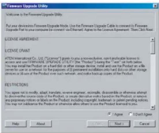
The Firmware Upgrade Utility Welcome screen appears: - Read the License Agreement (enable the I Agree radio button).
- Click Next to continue. The Firmware Upgrade Utility main screen appears:
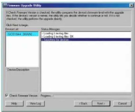
The Utility inspects your installation. All the devices capable of being upgraded by the package are listed in the Device List panel.
- As you select a device in the list, its description appears in the Device Description panel.
![Hardware Upgrade Utility If Check Firmware Version as checked, the utility compares the device's firmware level with the upgrade iles. If the device's version is never, the utility lets you decide whether to continue or not. If it is not checked, the utility performs the upgrade directly. Click Next to begin. Device List GCS1544 [MAIN]... Status Messages: Loading & testing files Loading & testing files: OK Steep-by-berries Device Description CPU: W738516 Device F:/V/ Ver 1.0.090 Upgrade F:/V/ Ver 1.0.090 MD: 000 Check Firmware Version Progress... Help View Log < Back Next > Cancel](/content/2026/05/984498/images/7410c674e09ecc840205eb4c78b201ece4bd14fe4831cea033f266eaa6a99981.jpg)
- After you have made your device selection(s), Click Next to perform the upgrade.
![The firmware [Ver 1.0.] is not newer than the current firmware [Ver 1.0.090] in device GCS1644 [MAIN]: 000 Continue the upgrade? [Yes/No]](/content/2026/05/984498/images/fa1b89fd10c67f5f9a33467fc46e281fa3ebb01bd867238ce0e7cf6f444a0136.jpg)
If you enabled Check Firmware Version, the Utility compares the device's firmware level with that of the upgrade files. If it finds that the device's version is higher than the upgrade version, it brings up a dialog box informing you of the situation and gives you the option to Continue or Cancel.
If you didn't enable Check Firmware Version, the Utility installs the upgrade files without checking whether they are a higher level, or not.
As the Upgrade proceeds, status messages appear in the Status Messages panel, and the progress toward completion is shown on the Progress bar.
Upgrade Succeeded
After the upgrade has completed, a screen appears to inform you that the procedure was successful: After the upgrade has completed, a screen appears to inform you that the procedure was successful:
![Forenee Upgrade Utility The Forenee upgrade was successful. Click: Finish to close the unit. Device List: GCS1644 [MAIN] ... Status Messages: Loading 5 testing files ... Loading 5 testing files: OK Searching for devices ... Preparing inverters upgrade ... Preparing inverters is not never than deviceCS1644A [EN190] : 200 Preparing inverters upgrade: OK Upgrading deviceCS1644A [EN190] 668 ... Upgrading deviceCS1644A [EN190] 668; OK Device Description: DPU: W78E516 Device FAV: Yes 1.0.090 Upgrade FAV: Yes 1.0.050 MD: 000 Forenee upgrade: OK Help View Log Finish Cancel](/content/2026/05/984498/images/2b7623b526a9c4ee74ff10499183ed541d4c174683995ce439828f94ad29a951.jpg)
Click Finish to close the Firmware Upgrade Utility.
After a successful completion, the switches exit Firmware Upgrade Mode, and reset themselves.
If you have a DCC mode installation be sure to reconnect the cable connected to the DCC port, and set the DCC switch back to Client on the appropriate switch (See Quad-View (DCC Mode), page 15).
Upgrade Fail
If the Upgrade Succeeded screen doesn't appear, it means that the upgrade failed to complete successfully, in which case you should do the following:
- Power off the GCS1642 / GCS1644 by removing the power jack.
- Invoke Firmware Upgrade Mode by holding down the Mode button on the front panel (see Mode button, page 6 & 8) and power on the GCS1642 / GCS1644. The orange LEDs flash together.
- Do the firmware upgrade procedure again.
Federal Communications Commission (FCC) Statement
This equipment has been tested and found to comply with the limits for a Class B digital device, pursuant to Part 15 of the FCC Rules. These limits are designed to provide reasonable protection against harmful interference in a residential setting. This product generates, uses, and can radiate radio frequency energy and, if not installed and used as directed, it may cause harmful interference to radio communications. Although this product complies with the limits for a Class B digital device, there is no guarantee that interference will not occur in a particular installation.
CE Statement
This device has been tested and found to comply with the following European Union directives: Electromagnetic Capability (2004/108/EC), Low Voltage (2006/95/EC) and R&TTED (1999/5/EC).
Limited Warranty
Warranty Information
This product carries a 3 Year Limited Warranty. For the terms and conditions of this warranty, please go to http://www.iogear.com/support/warranty
Register online at http://www.iogear.com/register
Important Product Information
Product Model ____
Serial Number ____
Contact
WE'RE HERE TO HELP YOU! NEED ASSISTANCE SETTING UP THIS PRODUCT?
Make sure you:
- Visit www.iogear.com for more product information
- Visit www.iogear.com/support for live help and product support
IOGEAR
www.iogear.com
iogear.custhelp.com
support@iogear.com

© 2018 IOGEAR®
- Table of Contents
- Package Contents
- System Requirements
- Console
- Computer
- Optional Audio
- GCS1642 Overview
- Front View
- Rear View
- GCS1644 Overview
- Single Stage Installation
- Step 1
- Step 2
- Step 3
- Step 4
- Step 5
- Step 6
- Final Step
- Quad View (DDC Mode)
- Note:
- LED Indication
- Port Switching
- Port Switching via Hotkeys
- Port Switching via Mouse
- Auto Scanning
- Hotkey Setting Mode (HSM)
- Mac Keyboard Emulation
- Sun Keyboard Emulation
- Factory Default Hotkeys Settings
- The Firmware Upgrade Utility
- Before you Begin
- Starting the Upgrade
- Upgrade Succeeded
- Upgrade Fail
- Federal Communications Commission (FCC) Statement
- CE Statement
- Limited Warranty
- Warranty Information
- Contact
- WE'RE HERE TO HELP YOU! NEED ASSISTANCE SETTING UP THIS PRODUCT?
- IOGEAR
Brand : IOGEAR
Model : GCS1644
Category : Computer accessory