GCS1214 - Computer accessory IOGEAR - Free user manual and instructions
Find the device manual for free GCS1214 IOGEAR in PDF.

User questions about GCS1214 IOGEAR
0 question about this device. Answer the ones you know or ask your own.
Ask a new question about this device
Download the instructions for your Computer accessory in PDF format for free! Find your manual GCS1214 - IOGEAR and take your electronic device back in hand. On this page are published all the documents necessary for the use of your device. GCS1214 by IOGEAR.
USER MANUAL GCS1214 IOGEAR
©2016 IOGEAR. All Rights Reserved. Part No. M1191-b M1192-b, the IOGEAR logo is trademarks of IOGEAR. Microsoft and Windows are registered trademarks of Microsoft Corporation. IOGEAR makes no warranty of any kind with regards to the information presented in this document. All information furnished here is for informational purposes only and is subject to change without notice. IOGEAR assumes no responsibility for any inaccuracies or errors that may appear in this document.
Table of Contents
| Conventions | 4 |
| Package Content 4 | |
| System Requirements 5 | |
| Overview | 6 |
| Hardware Setup 8 | |
| Operation | 11 |
| Specifications 12 | |
| Compliance Information 14 | |
| Limited Warranty 15 | |
| Contact | 15 |
Conventions
This manual uses the following conventions: Monospaced Indicates text that you should key in. [ ] Indicates keys you should press. For example, [Enter] means to press the Enter key. If keys need to be chorded, they appear together in the same bracket with a plus sign between them: [Ctrl+Alt].
- Numbered lists represent procedures with sequential steps.
- Bullet lists provide information, but do not involve sequential steps.
—> Indicates selecting the option (on a menu or dialog box, for example), that comes next. For example, Start —> Run means to open the Start menu, and then select Run.

Indicates critical information.
Package Content
1 x 2/4-Port dual link DVI secure KVM switch
1 x Power cord
1 x User manual
1 x Registration Form
Verify all the components are present and that nothing was damaged in shipping. If you encounter a problem, contact your dealer, or IOGEAR.
Read this manual thoroughly and follow the installation and operation procedures carefully to prevent any damage to the unit, and / or any of the devices connected to it.
System Requirements
Console:
- DVI monitor
• USB keyboard and mouse - Speakers and microphone
Computer:
• DVI port - Single or Dual Link DVI video card
- Type "A" USB port
Operating Systems:
- Windows® XP, Windows Vista®, Windows® 7, Windows® 8, Windows® 8.1, Windows® 10
• Mac OS 9 to 10.x - Oracle® Solaris
- Linux, UNIX and other USB supported systems*
*Additional drivers and support may be needed
**Dual-Link DVI-D USB 2.0 TAA compliant KVM Cables sold separately (G2L7D02UDTAA, G2L7D03UDTAA, G2L7D05UDTAA)
Overview
Front View

text_image
Secure KVM Switch 4-Port Dual-Link UVM 1 2 3 4 RESET 4 4 CAE RASSER POWERRear View

text_image
7 CONSOLE CPU 4 CPU 3 CPU 2 CPU 1 POWER 68 101 12 9 POWERNote: The GCS1214TAA has been used in these illustrations. The front and rear panels of the GCS1212TAA and the GCS1214TAA are the same, except the GCS1212TAA has two ports/port selection pushbuttons and the GCS1214TAA has four.
- Port LEDs- The Port LEDs are built into the Port Selection Pushbuttons. Online – Lights green to indicate that the computer attached to its corresponding port is up and running. Note: The green light for a given port is lit for as long as there is a powered on USB connection between the KVM switch and computer. Selected – Lights orange to indicate that the computer attached to its corresponding port has the KVM. Note: The Selected LEDs will flash constantly when a chassis intrusion is detected. See Chassis Intrusion Detection, page 12 for further details.
- Port Selection Pushbuttons- Pressing a Port Selection Pushbuttonbrings the focus to the computer attached to its corresponding port.
- Reset Button- Press this to reset the GCS1212TAA / GCS1214TAA to the default settings.
- Console Audio Ports- The cables from your main speakers and main microphone plug in here. The speakers and microphone plugged in here have priority over those in the rear panel.
- Power LED- Lights blue to indicate that the GCS1212TAA / GCS1214TAA is powered on.
- USB Console Ports- Your USB keyboard and mouse plug into these ports.
- Console Audio Ports- The cables from your main speakers and main microphone plug in here. The speakers and microphone plugged in here have priority over those in the rear panel.
- Console Monitor Port- The cable from your console monitor plugs in here.
- KVM Port Section- The custom KVM cables that attach to your computers plug in here.
- Power Switch- To turn the power on and off.
- Power Socket- Where the power cord is plugged in.
- Grounding Screw- See Grounding, page 8 for further details.
Hardware Setup
Before You Begin
- Make sure that the power to all devices connected to the installation are turned off. You must unplug the power cords of any computers that have the Keyboard Power On function.
- A computer connected to the KVM switch should only be powered on after all of the connections to the device are made (DVI, USB and audio).
Grounding
To prevent damage to your installation it is important that all devices are properly grounded.
Use a grounding wire to ground the GCS1212TAA / GCS1214TAA by connecting one end of the wire to the grounding terminal, and the other end of the wire to a suitable grounded object.
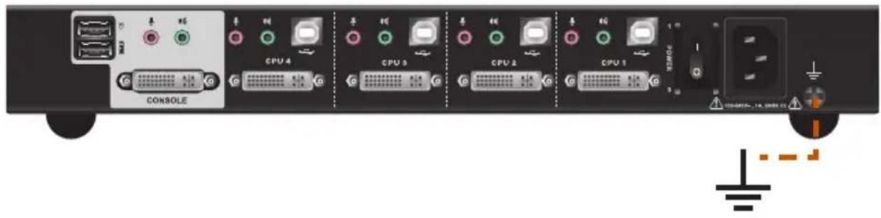
text_image
CONSOLE CPU 4 CPU 5 CPU 2 CPU 1 POWER TOMATO - 16.000 GBTo set up your GCS1212TAA / GCS1214TAA installation, refer to the installation diagram on the following page (the numbers in the diagrams correspond to the steps, below), and do the following:
- Plug your USB keyboard and USB mouse into the USB console ports located on the unit's rear panel.
- Plug your console monitor into the DVI console port located in the unit's rear panel and power on the monitor.
- Plug your microphone and speakers into the console microphone and speaker jacks located on the unit's front or rear panel. The microphone and speakers plugged into the front panel have priority over those in the rear panel.
- Using a KVM cable set (not supplied in the package and should be purchased separately), plug the DVI connector into any available DVI socket in the KVM port section of the switch, then plug the accompanying USB, microphone and speaker connectors into their corresponding USB, microphone, and speaker sockets.
- At the other end of the cable, plug the USB, video, microphone, and speaker cables into their respective ports on the computer.
- Check that the USB seal is still attached to the CAC reader port to prevent unintended usage.
- Plug the female end of the power cord into the GCS1212TAA / GCS1214TAA's power socket; plug the male end into an AC power source.
- Powering On.
Installation Diagram
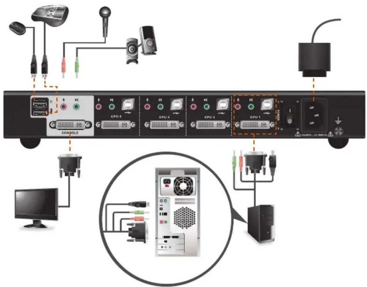
text_image
Diagram showing connected hardware components including computer, monitor, and server via CPU interfaces with labeled ports and connectorsOperation
Powering On
When you power on your computers, GCS1212TAA / GCS1214TAA emulates both a mouse and keyboard on each port and allows your computers to boot normally. The default selected port at switch power on is the lowest port with a computer connected. The selected computer will be displayed on the console monitor.
Note: The default connection is determined by the lowest numbered DVI connection that is powered on.
Manual Switching
For increased security, GCS1212TAA / GCS1214TAA offers manual port-switching only. This is achieved by pressing the port selection pushbuttons located on the unit's front panel.
Press and release a port selection pushbutton to bring the KVM focus to the computer attached to its corresponding port (see Port ID Numbering, below). The Selected LED lights orange to indicate that the computer attached to its corresponding port has the KVM.
Port ID Numbering
Each KVM port on the GCS1212TAA / GCS1214TAA is assigned a port number (1–2 for the GC-S1212TAA; 1–4 for the GCS1214TAA). The port numbers are marked on the rear of the switch. See Rear View, page 6. The port ID of a computer is derived from the KVM port number it is connected to.
LED Display
In addition to the Power LED, the GCS1212TAA / GCS1214TAA has port LEDs (Online and Selected) that are built into the port selection pushbuttons to indicate port operating status, as shown in the table below:
LED Indication
Power Lights blue to indicate that the GCS1212TAA / GCS1214TAA is powered on
Online Lights green to indicate that the computer attached to its corresponding port is up and running. Note: The green light for a given port is lit for as long as there is a powered on USB connection between the KVM switch and computer.
Selected Lights orange to indicate that the computer attached to its corresponding port has the KVM.
Chassis Intrusion Detection
To help prevent malicious tampering with the GCS1212TAA / GCS1214TAA, the switch becomes inoperable and the Selected LEDs flash constantly when a chassis intrusion, such as the cover being removed, is detected.
CAC Reader
The usage of the CAC Reader port is not covered in this evaluation. Make sure the USB seal is in place to maintain the integrity of this device.
Specifications
| Function GCS1212TAA GCS1214TAA | |||||
| Computer Connections 2 4 | |||||
| Port Selection Pushbutton | |||||
| Connectors Console Keyboard 1 x USB Type-A F (Black) | |||||
| Function GCS1212TAA GCS1214TAA | |||
| Power Consumption 120V / 5.1W; | 230V / 5.1W | 120V / 6.1W;230V / 5.7W | |
| Environment | Operating Temp. 0–40°C | ||
| Storage Temp -20–60°C | |||
| Humidity 0–80% RH, Non-condensing | |||
| Physical Properties | Housing Metal | ||
| Weight 3.85 Lbs 4.00 Lbs | |||
| Dimensions (L x W x H) 13” x 6” x 2” | |||
Compliance Information
Federal Communications Commission (FCC) Statement
This equipment has been tested and found to comply with the limits for a Class B digital service, pursuant to Part 15 of the FCC rules. These limits are designed to provide reasonable protection against harmful interference in a residential installation. Any changes or modifications made to this equipment may void the user's authority to operate this equipment. This equipment generates, uses, and can radiate radio frequency energy. If not installed and used in accordance with the instructions, may cause harmful interference to radio communications. However, there is no guarantee that interference will not occur in a particular installation. If this equipment does cause harmful interference to radio or television reception, which can be determined by turning the equipment off and on, the user is encouraged to try to correct the interference by one or more of the following measures:
- Reorient or relocate the receiving antenna.
- Increase the separation between the equipment and receiver.
- Connect the equipment into an outlet on a circuit different from that to which the receiver is connected.
- Consult the dealer or an experienced radio/TV technician for help.
FCC Caution: Any changes or modifications not expressly approved by the party responsible for compliance could void the user's authority to operate this equipment.
Limited Warranty
Warranty Information
This product carries a 4 Year Limited Warranty.
For the terms and conditions of this warranty, please go to http://www.iogear.com/support/warranty
Register online at http://www.iogear.com/register
Important Product Information
Product Model ____
SerialNumber ____
Contact
WE'RE HERE TO HELP YOU! NEED ASSISTANCE SETTING UP THIS PRODUCT?
Make sure you:
-
Visit www.iogear.com for more product information
-
Visit www.iogear.com/support for live help and product support
IOGEAR
www.iogear.com
iogear.custhelp.com
support@iogear.com